Inflammable Gas Mixture Detection with a Single Catalytic Sensor Based on the Electric Field Effect

Abstract
: This paper introduces a new way to analyze mixtures of inflammable gases with a single catalytic sensor. The analysis technology was based on a new finding that an electric field on the catalytic sensor can change the output sensitivity of the sensor. The analysis of mixed inflammable gases results from processing the output signals obtained by adjusting the electric field parameter of the catalytic sensor. For the signal process, we designed a group of equations based on the heat balance of catalytic sensor expressing the relationship between the output signals and the concentration of gases. With these equations and the outputs of different electric fields, the gas concentration in a mixture could be calculated. In experiments, a mixture of methane, butane and ethane was analyzed by this new method, and the results showed that the concentration of each gas in the mixture could be detected with a single catalytic sensor, and the maximum relative error was less than 5%.1. Introduction
The analysis of mixtures of inflammable gases is very important for safety monitoring in mines because coal mine explosions are often caused by combustible gases. Therefore, gas monitoring systems must be installed in coal mines for the real-time monitoring of combustible gases [1]. There are usually three kinds of sensors used for gas monitoring in coal mines: infrared sensors, thermal conductivity sensors and catalytic sensors. The principle of the infrared gas sensor is to detect the infrared intensity after measuring the infrared spectrum of the gases. The principle of the thermal conductivity sensor is to detect the resistance variation due to the heat conduction of different gas concentrations. A catalytic sensor is a chemical sensor, which detects combustible gases by the resistance changes caused by the oxidation reaction of gases on the sensor. Infrared gas sensors are expensive, and their accuracy is easily influenced by the humidity in mines [2]. Thermal conductivity gas sensors are easily affected by the environment, and the ventilation and humidity in the mine could affect the reliability of the sensor [3]. With a simple structure, low cost and stable performance in mine environments, catalytic gas sensors are widely used for gas monitoring in mines.
The main cause for explosions in coal mines is the ignition of methane (CH4) so catalytic sensors are usually used to monitor methane [4]. However, coal residues often emit methane, C2H6, C4H10 and other combustible gases under high temperature [5]. The lower explosive limits of CH4, C4H10 and C2H6 are 5%, 3% and 1.8%, respectively, so the explosive concentrations of C2H6 or C4H10 are far lower than those of methane. Some research has shown that if CH4 was mixed with C2H6 or C4H10, the lower explosive limit of the gas mixture would be reduced and the risk of explosion would increase [6]. Therefore, monitoring methane with catalytic sensors for judging the possibility of explosions in mines will have larger errors. In order to solve this problem, it is necessary to analyze the concentration of each combustible gas in a gas mixture, then the explosive value will be obtained by the calculation of the concentration of each combustible gas, and the danger of explosion will be reasonably judged on the basis of the calculation result.
Although there are a variety of instruments for gas analysis on the market, they are not suitable for use in coal mines. At present, there is some research on the analysis of mixed gases in coal mines. Liu introduced a method for gas analysis based on infrared absorption technology [7]. The analysis system was made up of a broadband mid-infrared light source and a detector with a narrow-band filter. Each signal of the detector's outputs corresponded to a kind of gas according to its absorption wavelength. The gases were analyzed by a BP neural network using experimental data. The result showed that the relative error for gas analysis was less than 5%. Huang proposed a new method for gas analysis based on support vector machine (SVM) and multi-sensor data fusion. He used a multi-class classifier to fuse data of a sensor array composed of gas sensors, a temperature sensor and humidity sensor. The data fusion effectively eliminated the influence of ambient temperature and humidity on the gas sensors, and resulted in the identification of the gases [9]. Tong introduced a new method for the analysis of mixed inflammable gases with a catalytic sensor [9]. The catalytic sensor worked at different temperatures and had different outputs. The sensor's outputs were processed with a BP artificial neural network and the gases were analyzed after the model and algorithm were established through data training. The experimental results with three mixed gases showed that the method could accurately identify and analyze mixed gases.
In the above research, the gas analysis with an infrared sensor or thermal conductivity sensor could be influenced by the humidity and is not suitable for application in coal mines. The method using a catalytic sensor at different working temperatures seems to be feasible for the analysis of mixed combustible gases, but before any catalytic sensor can be used, it must undergo an aging process in which the sensor works for one week at a rated temperature of 400 °C and reaches a steady state, as changing its working temperature will make the output instable and influence its normal work [10].
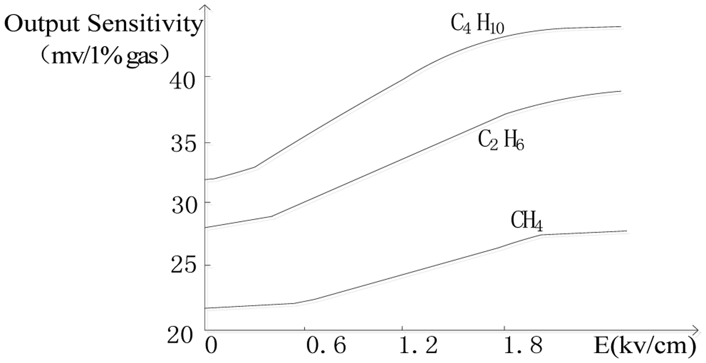
In our study of catalytic sensors, we found that different electric fields could change the rate of the oxidation reaction of combustible gases on the sensor's surface and affect the output sensitivity of the catalytic sensor [11]. Figure 1 shows the output of a Wheatstone bridge circuit with a catalytic sensor exposed to CH4, C4H10 and C2H6 under different electric fields. The research results showed that as the field strength increased, the output sensitivity of the catalytic sensor for combustible gases increased. We will use these findings for the analysis of mixed combustible gases
2. Operating Principle of the Catalytic Sensor
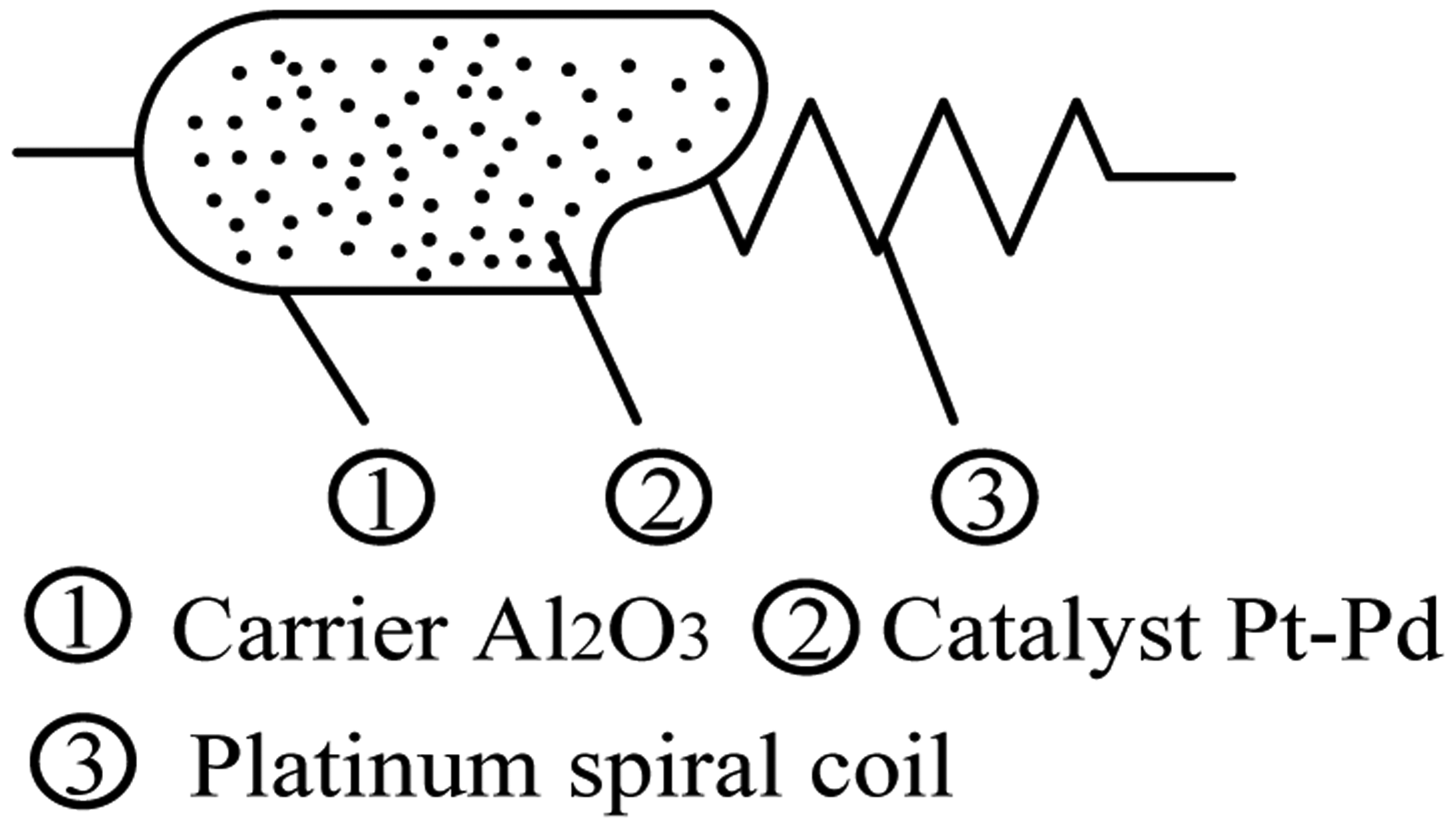
The catalytic sensor is obtained by coating Al2O3 as carrier on a platinum wire and depositing Pt or Pd in the catalyst, as shown in Figure 2.
Its working principle is an oxidation reaction of the flammable gases on the sensor under the action of the sensor's catalyst and high temperature caused by the electrical current on the sensor, which is about 400 °C [12]. The oxidation reaction of combustible gases will produce a lot of heat to increase the sensor's temperature, and then the resistance of the sensor will increase with the temperature characteristics of the platinum in the sensor. The concentration of combustible gas could be detected when the change sensor's resistance is converted into electrical signals with some kind of circuit.
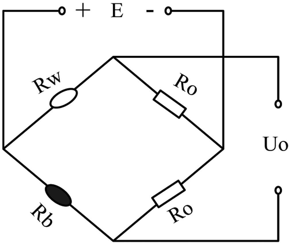
The detection circuits for a catalytic sensor are usually of two kinds. The first kind is a Wheatstone bridge circuit and the other is a constant temperature detection circuit with automatic regulation of the sensor's current. Wheatstone bridge detection circuit as shown in Figure 3, which is made up of a compensating element (Rw), catalytic sensor (Rb) and two resistances Ro [13]. The compensating element is made by coating Al2O3 as carrier on a platinum wire and can eliminate the influence of environmental temperature on the catalytic sensor.
The bridge circuit is used to detect methane as an example. The catalytic sensor is electrically heated to about 400 °C, and at this temperature catalytic oxidation of the methane occurs readily. The oxidation reaction is as seen in Equation (1). The oxidation reaction of methane causes the increase of the temperature and resistance of the sensor, which is then measured by incorporating the element in the Wheatstone bridge network where the potential difference across the bridge forms the output of the device:
The resistance of the sensor increases to Rb + △Rb, but the remaining resistances in the bridge remain the same, thus the bridge becomes unbalanced and the output voltage can be described as:
In this way, the methane concentration can be detected by measuring the variation of output voltage from this unbalanced Wheatstone bridge.
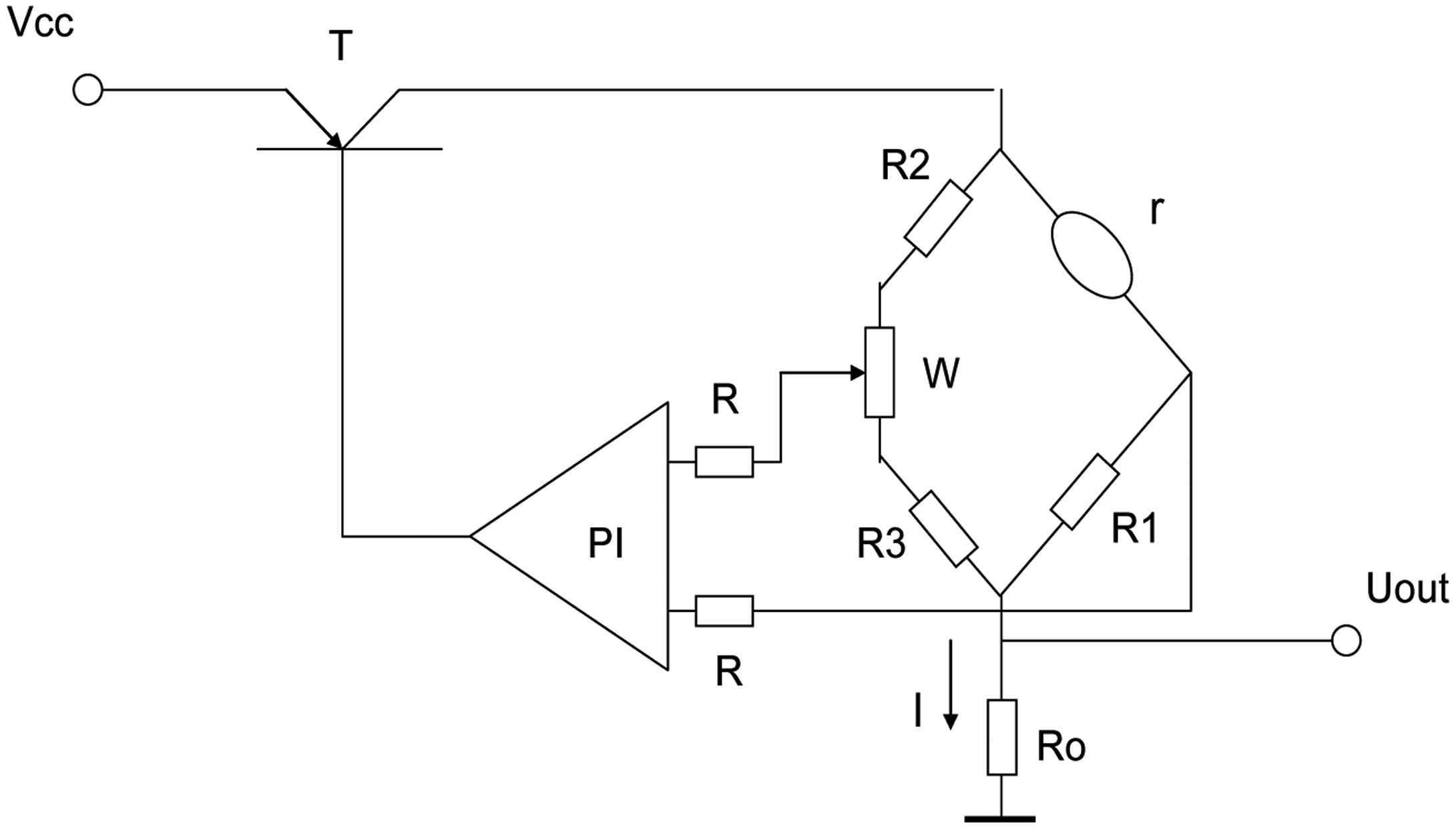
The constant temperature detection circuit is shown in Figure 4. The detection circuit is composed of a bridge, which is formed with resistors R1, R2, R3, potentiometer W and catalytic sensor, PI regulator, regulating switch T and the sampling resistance R0. According to the 400 °C working temperature current of the catalytic element sensor, we take the current flowing through the catalytic element sensor as the initial current (I = I0) by adjusting the potentiometer W. Assume R2 = R3 ≫ R1 = r, then the current through the catalytic element sensor is approximately equal to that going through the sampling resistor R0 [14].
When in the detection of the combustible gas the gas starts to oxidize on the catalytic element sensor it will tend to generate heat which will increase the catalytic element's temperature and the resistance of the sensor, but by controlling and adjusting switch T and the PI regulator, then the working current through the catalytic element sensor will automatically reduce to maintain its temperature and resistance constant. The reduced current I reflects the concentration of measured gas, so the output of the constant temperature detection circuit is Uout = IR0.
In the above two detection circuits, the constant temperature detection circuit is better than the Wheatstone bridge circuit. In the Wheatstone bridge circuit, the temperature of the catalytic sensor will increase with the increase of concentration of combustible gas, and thermal stability and activity of the catalytic elements decline. In the constant temperature detection circuit, the temperature of the catalytic sensor is stable and its stability is much improved, so we will use the constant temperature detection circuit for the analysis of mixed combustible gases.
3. Gas Detection Principle
The static thermal equilibrium equation of catalytic sensor is shown below [15]:
The left side of Equation (3) is the total heat energy, which is the sum of the heat I2r generated by working current through the sensor and the energy Q produced by the oxidation reaction of the combustible gas on the catalytic sensor's surface. The right side is the total heat loss of the conduction heat loss and the radiation heat loss of the sensor. I is the current through the sensor, r is the resistance of the catalytic sensor, T is the temperature of catalytic sensor, T0 is the environment temperature, and α, S, A, σ are the physical parameters associated with the material structure of the catalytic sensor:
We set k(E) as the heat sensitivity coefficient which is associated with the electric field intensity and can be obtained through experiments, C as the measured gas concentration. ; if the environment temperature is certain, D is a constant.
When analyzing the gas mixture with n kinds of mixed gases, we can get outputs I1 to In by adjusting the electric field n times. Then there are independent thermal equilibrium equations as follows:
In Equation (5), the temperature is constant, so resistance ri is unchanged. Then we can calculate the concentration Ci based on Cramer's Rule:
As Ii = Uout(i)/R0, Ii can be calculated from output voltage Uout in Figure 4. The solution Ci is the concentration of each gas in mixture gases.
4. Experiment Results and Analysis
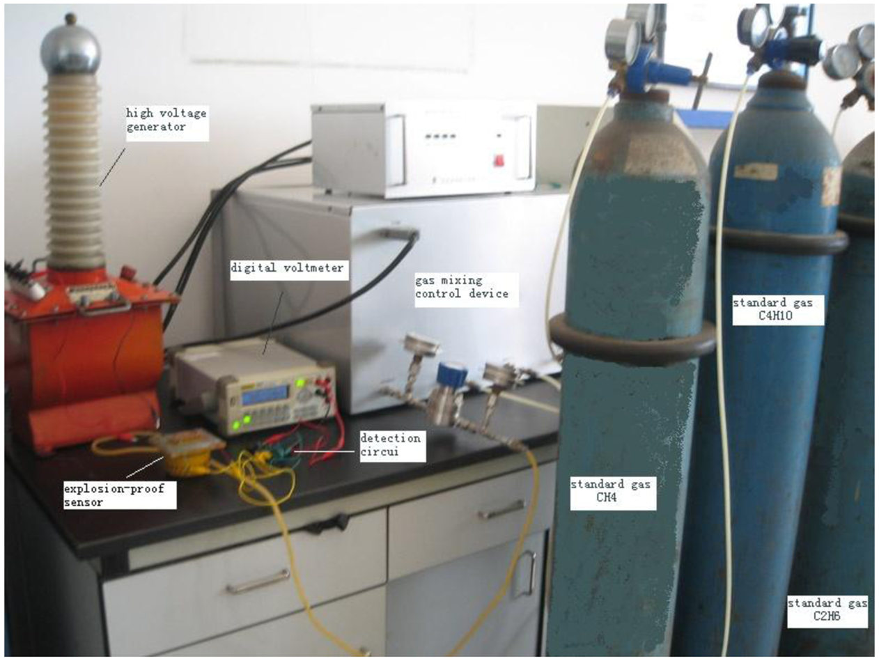
We take a mixture of gases containing CH4, C4H10 and C2H6 for the analysis experiments with a SH-3 catalytic sensor. The control voltages for the electrical field are 0 KV, 1.2 KV and 2.0 KV. The experimental system includes a high voltage generator, digital voltmeter, standard gases CH4, C4H10 and C2H6, a gas mixing control device, detection circuit and an explosion-proof sensor, as shown in Figure 5.
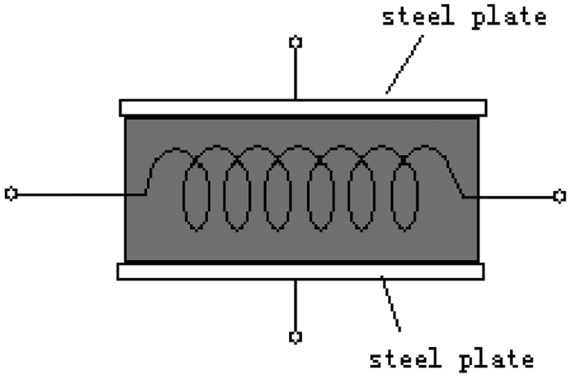
To study the gases' analysis by the electric field effect on the catalytic sensor, we need a specific catalytic sensor. This sensor was made from a normal sensor with two 0.2 mm thick stainless steel plates on both sides, as shown in Figure 6. We can provide an electrical field on the sensor using the two plates.
First, we obtained the individual heat sensitivity coefficients kij of CH4, C4H10 and C2H6 in different E-fields by the measurement of 1% concentration of each gas. The coefficients of methane k11, k21 and k31 correspond to 22 mv/1%, 24 mv/1%, 26 mv/1%; the coefficients of butane k12, k22 and k32 correspond to 32 mv/1%, 35 mv/1%, 38 mv/1%; the coefficients of ethane k13, k23 and k33 correspond to 28 mv/1%, 30 mv/1%, 32 mv/1%. Then we detected the mixture of gases by adjusting the electric field on the sensor and get the output signals I1, I2 and I3, Lastly we obtained the concentrations of methane, butane and ethane by solving Equation (3). The results are shown in Table 1.
From the results, we can see that there is an error because of the nonlinearity of the catalytic sensor, but the maximum relative error is less than 4% and this meets the requirements of relevant standards. The experiment showed that we could obtain the concentration of each gas in a mixture using the constant temperature detection circuit and the control of the electric field on the sensor. Catalytic sensors on the market usually have a compensation element whose role is to eliminate the influence of the environmental temperature on the catalytic sensor.
In the bridge detection circuit, a compensation element is used with the catalytic sensor. Its output is not affected by the environmental temperature, but in the constant temperature detection circuit, without the compensating element, the output will be influenced by the environmental temperature, because the catalytic sensor is made of platinum wire which is sensitive to temperature. How to solve this problem? Can the compensating element also be set into the bridge of the constant temperature detection circuit? Suppose R1 was replaced by the compensation element in Figure 4, then the bridge was balanced with R1 = r through the potentiometer W.
If such a circuit was used to detect combustible gas, the sensor's resistance would increase to r > R1, the bridge would have no balance, the circuit would automatically decrease the sensor's current and attempt to decrease r and restore the balance of the bridge. Because the platinum wires in the catalytic sensor and the compensating element are identical, the changes of their current would make their resistance undergo the same change, and finally the current would be adjusted to zero and the detection circuit would stop working. This is the reason why the compensating element was not used in the constant temperature detection circuit.
In order to solve the problem of temperature compensation of the temperature detection circuit, a platinum resistance with a great resistance was used to replace R2, also R2 = R3. In this circuit, if the environmental temperature changes, the change rate of resistance of the catalytic sensor is the same as R2. Assuming the same change rate is α, αR1R2 = αrR3, the bridge remains in balance with unchanged current that is the result of temperature compensation. The temperature compensation was proved by the experimental results in Table 2.
In the experiments in Table 2, the indoor temperature is 22 °C. The detection circuit was adjusted so the outputs were almost same whether the compensation resistor was used in the circuits or not, but when the detection circuit without compensation resistor was put into the constant temperature test box at the temperatures of 40 °C or 0 °C, the output error increase was more than the allowed error of relevant standards. After adding the compensation resistor, the output of the detection circuit was almost not influenced by the temperature, the maximum relative error was less than 5% and suitable for the practical requirements.
5. Conclusions
Based on our discovery that an electrical field could affect the sensibility of a catalytic sensor, we used a constant temperature detection circuit and provided an adjustable electric field to the sensor for the analysis of mixtures of gases. From the output signals of the detection circuit, the concentration of each gas in a mixture could be established by calculating the static thermal balance equation of the catalytic sensor. The results of experiments with methane, butane and ethane proved that an inflammable gas mixture could be analyzed with a single catalytic sensor. In order to solve the problem of the influence of environmental temperature on the catalytic sensor, a platinum resistance was used to replace the resistor and it showed good temperature compensation.
Acknowledgments
This work was supported by a grant from Key Projects in the National Science & Technology Pillar Program during the Eleventh Five-Year Plan Period.(No. 2013BAK06B08).
Author Contributions
In this paper, Ziyuan Tong presented the design of multicomponent gas analyzing circuit and prepared the draft manuscript, Min-Ming Tong, solved the problem of temperature compensation in the constant temperature detection circuit and proofed the manuscript, Wen Meng conducted signal processing and data analysis. Meng Li was responsible for the experimental works and data collecting.
Conflicts of Interest
The authors declare no conflict of interest.
References
- Yin, W.; Fu, G.; Yuan, S.; Dong, J. Study on Basic Characteristics and Occurrence Regularity of Major Gas Explosion Accidents in Chinese Coal Mines during 2001–2012. China Saf. Sci. J. 2013, 23, 141–147. [Google Scholar]
- Shi, F. The Influence of Coal Dust and Humidity on Infrared Gas Sensor. Saf. Coal Mines 2013, 44, 172–174. [Google Scholar]
- Huang, W.; Ren, Z.; Tong, M. Analysis of Reasons Affecting Gas Detection Performance of thermal Conductivity Sensor. Comput. Autom. Meas. Control 2004, 12, 1005–1008. [Google Scholar]
- Wang, R.L. A study of mining catalytic methane sensor with high stability. J. China Univ. Min. Tech. 1984, 3, 1–11. [Google Scholar]
- Jiang, C.L.; Yang, S.Q.; Song, W.X. Determination of Index Gas in Coal Oxidation Process. Saf. Coal Mines 2012, 43, 185–188. [Google Scholar]
- Zhang, G.; Tong, M.; Ren, Z. Experimental Studies on Effect of Alkane Gases to Lower Explosion Limits of Manthane. J. Kunming Univ. Sci. Technol. 2011, 36, 6–9. [Google Scholar]
- Liu, B.; Tong, M.; Wang, J. Detection of Multi—Component Mixed Gas Based on Infrared Absorption Technology. Saf. Coal Mines 2011, 42, 5–8. [Google Scholar]
- Huang, W.Y.; Ren, Z.H.; Tong, M.M. Multi-gases qualitative identification using SVM and data fusion. Comput. Eng. Appl. 2009, 45, 241–245. [Google Scholar]
- Tong, M.; Zhang, Y.; Qi, M. The Mixed Inflammable Gas Analysis Based on BP Neural Network. Acta Metrol. Sin. 2006, 27, 169–171. [Google Scholar]
- Wang, R.L. A study of mining catalytic methane sensor with high stability. J. China Univ. Min. Tech. 1984, 3, 1–11. [Google Scholar]
- Tong, M.; Li, J.; Huang, Y.; Dai, X. Effect of electric field to catalytic sensor. Proceedings of 2006 International Conference on Information Acquisition, Weihai, China, 20–23 August 2006; pp. 1005–1009.
- Jiang, B.Y.; Zhang, N.C.; Liu, M. The summary of methane detecting sensors. Shanxi Coking Coal Sci. Tech. 2008, 5, 4–6. [Google Scholar]
- Wang, Y.; Tong, M.M.; Zhang, D. Improving the Performance of Catalytic Combustion Type Methane Gas Sensors Using Nanostructure Elements Doped with Rare Earth Cocatalysts. Sensors 2011, 11, 19–31. [Google Scholar]
- Wang, R.L. Mining Environment Sensing Technology; China University of Mining and Technology Press: Xuzhou, China, 1998; pp. 10–25. [Google Scholar]
- Tong, M.; Niu, M.; Tong, Z.; Liu, X.; Dai, X. Improvement of the dynamic characteristics on catalytic sensor. Proceedings of 9th International Conference on Electronic Measurement & Instruments, Beijing, China, 16–19 August 2009; pp. 899–903.


| Actual Concentration /% | Test Results /% | Maximum Relative Error /% | ||||
|---|---|---|---|---|---|---|
| CH4 | C4H10 | C2H6 | CH4 | C4H10 | C2H6 | |
| 1.10 | 0.85 | 1.85 | 1.14 | 0.82 | 1.83 | 3.63 |
| 2.00 | 0.64 | 1.58 | 1.95 | 0.62 | 1.54 | 3.52 |
| 2.80 | 0.50 | 1.05 | 2.72 | 0.46 | 1.02 | 2.85 |
| Gas | Maximum Relative Error/% | |||||
|---|---|---|---|---|---|---|
| CH4 | C4H10 | C2H6 | ||||
| Actual Concentration (%) | 1.10 | 0.85 | 1.85 | n/a | ||
| Temperature | 0 °C | No Compensation | 1.01 | 0.78 | 1.75 | 8.24 |
| Compensation | 1.13 | 0.82 | 1.81 | 3.53 | ||
| 22 °C | No Compensation | 1.14 | 0.82 | 1.83 | 3.64 | |
| Compensation | 1.14 | 0.82 | 1.83 | 3.64 | ||
| 40 °C | No Compensation | 1.20 | 0.91 | 2.02 | 9.19 | |
| Compensation | 1.15 | 0.83 | 1.84 | 4.55 | ||
© 2014 by the authors; licensee MDPI, Basel, Switzerland. This article is an open access article distributed under the terms and conditions of the Creative Commons Attribution license ( http://creativecommons.org/licenses/by/3.0/).
Share and Cite
Tong, Z.; Tong, M.-M.; Meng, W.; Li, M. Inflammable Gas Mixture Detection with a Single Catalytic Sensor Based on the Electric Field Effect. Sensors 2014, 14, 6409-6418. https://doi.org/10.3390/s140406409
Tong Z, Tong M-M, Meng W, Li M. Inflammable Gas Mixture Detection with a Single Catalytic Sensor Based on the Electric Field Effect. Sensors. 2014; 14(4):6409-6418. https://doi.org/10.3390/s140406409
Chicago/Turabian StyleTong, Ziyuan, Min-Ming Tong, Wen Meng, and Meng Li. 2014. "Inflammable Gas Mixture Detection with a Single Catalytic Sensor Based on the Electric Field Effect" Sensors 14, no. 4: 6409-6418. https://doi.org/10.3390/s140406409