A Wireless Swing Angle Measurement Scheme Using Attitude Heading Reference System Sensing Units Based on Microelectromechanical Devices

Abstract
: Feasible real-time swing angle measurement is significant to improve the efficiency and safety of industrial crane systems. This paper presents a wireless microelectromechanical system (MEMS)-based swing angle measurement system. The system consists of two attitude heading reference system (AHRS) sensing units with a wireless communication function, which are mounted on the hook (or payload) and the jib (or base) of the crane, respectively. With a combination of a three-axis accelerometer, a three-axis gyroscope and a three-axis magnetometer, the standard extended Kalman filter (EKF) is used to estimate the desired orientation of the payload and the base. Wireless ZigBee communication is employed to transmit the orientation of the payload to the sensing unit mounted on the base, which measures the orientation of the base. Because several physical parameters from the payload to the base can be acquired from the original crane control system, the swing angles of the payload can be calculated based on the two measured orientation parameters together with the known physical parameters. Experiments were performed to show the feasibility and effectiveness of the proposed swing angle measurement system.1. Introduction
Industrial cranes are widely used in harbors, docks, warehouses, construction sites and other industrial sites. They are desired for transferring goods in a fast and safe way. However, due to the acceleration of the cart, the swinging of the payload is inevitable. Therefore, it is necessary to anti-sway control the crane with experienced operators or an automatic control system. To suppress the payload swing of crane systems, many schemes have been developed over recent years [1–4]. Generally, the developed schemes could be categorized into open-loop anti-swing control and closed-loop anti-swing control. The open-loop anti-swing control mainly includes optimal time control [5] and input shaping control [6]. The key disadvantage of the open-loop anti-swing control is that the control system is not robust with the parameter changing and unforeseen disturbances. The closed-loop anti-swing control scheme could achieve better trajectory control performance and robustness on parameter variation and unforeseen disturbances. However, closed-loop anti-swing control schemes are based on feedback information, especially the swing angles [2,3,7,8].
Currently, some researchers have estimated or observed the swing angles, other than measuring them with sensors directly. For example, Gholabi et al. [1] employed the voltage and current of the induction motor, which drives the trolley, to estimate swing angles for damping control of the payload swing. Ebrahimi et al. [9] estimated the swing angles based on the load cell installed in the trolley for feedback control of the overhead crane. To measure the swing angles directly, they can be acquired based on optical encoders [10], potentiometers [5], cameras [11–14], accelerometers or inclinometers [15,16] and other types of sensors. Generally, optical encoder- and potentiometer-based angle measurement could be suitable only for a lab crane setup. Vision-based swing angle measurement suffers from high cost and the industrial environment. Accelerometer or inclinometer sensors are competitive for swing angle measurement, especially with the development of the MEMS technology, which leads to low cost accelerometers or inclinometers. Once these accelerometers or inclinometers are attached to some special locations (normally a hook or trolley) of the crane body, the swing angles can be calculated based on the geometry of the crane system. The flaw of using an accelerometer or inclinometer only to measure the swing angles is that the payload will rotate along the rope in some cases. Therefore, the orientation sensors should meet all of the cases.
Orientation estimation systems have been widely applied in airplanes, virtual reality, game systems, robotic systems, unmanned aerial vehicles, etc. For example, an aerial vehicle needs orientation information to stabilize its attitude [17]. Traditionally, such sensing systems are very expensive, because they use high resolution and low bias sensors, and they usually find applications in commercial airplanes. With the advancement of MEMS technology, various low-cost motion sensors are widely available nowadays. The output of these sensors, however, has a low resolution, high noise and a time-varying bias term. Therefore, sophisticated fusion algorithms are needed to estimate the orientations. Some AHRS sensors are already available in the market nowadays. For example, the AHRS440 from Crossbow Technology [18], the 3DM-GX3-25 from Microstrain [19], the VN-100 from VectorNav [20], the MTi from Xsens [21], InertiaCube from Intersense [22], ChR-6dm from CHRobotics [23], etc. Most of them are quite expensive, except the VN-100 from VectorNav and ChR-6dm from CHRobotics. Moreover, ChR-6dm from CHRobotics is open source, which means we can modify the firmware on it.
In this paper, two MEMS-based AHRS sensors will be used to calculate the swing angles of the crane system. The two sensors are installed on the hook (or payload) and the jib (or crane body) to measure the orientation of the payload and the crane body, respectively Based on the measured parameters, swing angles of the payload can be calculated together with geometrical parameters of the crane system.
The rest of the paper is organized as follows. The swing angle measurement system will be described in Section 2. After that, in Section 3, the deduction of swing angles with two MEMS-based AHRS sensors will be presented in detail, including static orientation calculation, orientation update and swing angles calculation. The experimental setup and implementation of the swing angles measurement scheme will be demonstrated and discussed in Section 4. Finally, conclusions and future work will be summarized in Section 5.
2. The Proposed Swing Angles Measurement Scheme
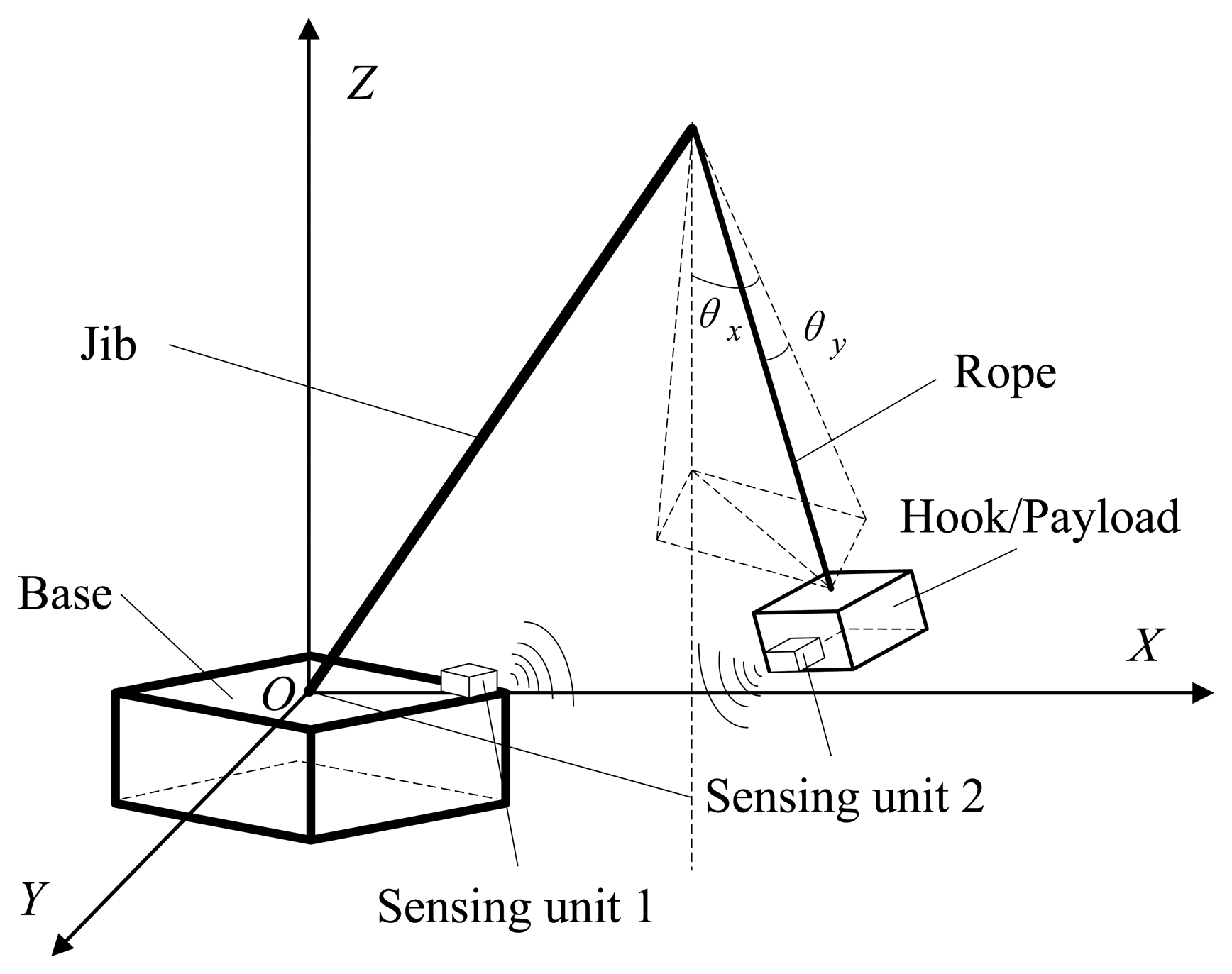
The proposed swing angles measurement scheme for a mobile crane system can be described as shown in Figure 1. The swing motion of the payload of other types of crane systems can be described similarly. Inertial coordinates OXYZ are attached on the base, which means the crane body. The spatial swing angles of the payload could be denoted with two plane swing angles θx and θy. Our task is to acquire the real-time dynamic data of the two angles for monitoring and anti-swing control of the payload.
The angles measurement scheme is to use two MEMS-based AHRS sensors with a wireless communication function, as shown in Figure 1. Sensing Unit 1 can be installed near the control box of the crane system, and Sensing Unit 2 is installed on the hook or the payload. Each sensing unit can measure the orientation of the object on which it is fixed. We denote the orientation of the payload as “body” coordinates and the orientation of the crane base as “inertial” coordinates. Sensing Unit 2 will send its orientation, i.e., pitch (θ), roll (ϕ) and yaw (ψ) angles, to Sensing Unit 1, which measures the orientation of the crane body. As the orientation of the top end of the jib can be calculated with the known parameters of the crane and the orientation of the base, the two swing angles θx and θy therefore can be calculate based on the two measured orientation angles of the base and the payload together with the physical parameters of the crane. The calculated swing angles θx and θy then could be sent to the control box of the crane system through cabled serial communication for monitoring and/or closed-loop anti-swing control design.
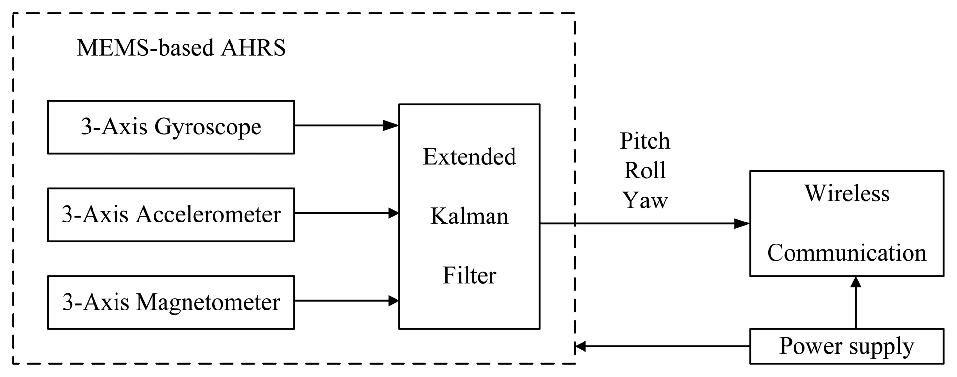
The diagram of each sensing unit can be illustrated as shown in Figure 2. The AHRS sensor is mainly based on three MEMS devices: three-axis accelerometer having output a = [ax, ay, az]T, three-axis magnetometer having output h = [hx, hy, hz]T and three-axis gyroscope having output ω = [ωx, ωy, ωz]T. The sensing signals from the devices will be integrated to estimate the orientation (pitch, roll, yaw angles) based on fusion algorithms, such as EKF. Additionally, the pitch (θ), roll (ϕ) and yaw (ψ) angles measured by one sensing unit can be sent to other units through wireless communication in real time. The advantages of the designed sensing unit are the low cost, compact size, low energy consumption, robustness to the different weather environments, and so on.
3. Derivation of Swing Angles
The derivation of swing angle measurement for crane systems includes three key steps:
- (1)
initializing the orientation of each AHRS sensing unit;
- (2)
updating the orientation of each AHRS sensing unit with EKF;
- (3)
calculating swing angles based on the data from the two AHRS sensors together with the physical parameters of the crane body.
The main symbols used in the paper and their description have been summarized and listed in Table 1.
3.1. Initial Orientation Calculation
A three-axis accelerometer can measure accelerations along each axis in the body frame. In the static state, the sensor is subjected to gravitational acceleration. In this case, we can obtain the angles between the sensing axis and the gravitational force, so that the accelerometers are used to perform leveling. In other words, we can use the three-axis accelerometer to get the pitch and roll angles of the object in the static state. By comparing the outputs of three orthogonal accelerometers with gravity, the tilt angles between the b (body) frame and the l (level) frame can be determined. The output of the accelerometer in the b frame is denoted as , while the gravity in the l frame is denoted as (0, 0, g). With the orientation transformation matrix from the b frame to the l frame , we have:
Since the leveling angles have no relationship to the yaw angle ψ, the transformation matrix can be expressed as:
Therefore,
Because the values of , and are measured directly by the accelerometer and the gravity is constant (g = 9.78 m/s2), we can calculate the pitch angle θ and roll angle ϕ as:
Similarly to the accelerometer, for a three-axis magnetometer, as we know that the horizontal component of the earth magnetic field always points north, its direction could be decided by the horizontal components Hx and Hy in the l frame, which are the magnetic field along the north and east in the inertial frame. The relationship between the two horizontal components in the l frame and the output of magnetometer in the b frame can be expressed as:
From the formula above, we can get:
Therefore, the yaw angle can be calculated as:
In practical engineering applications, the quaternion is used to describe the change of orientation q = [q1, q2, q3, q4]T, since it can avoid singularities. Initial quaternion is obtained in general from the transformation matrix obtained at the initial alignment stage. The conversion from Euler angles to the quaternion is as follows:
3.2. Orientation Update
From the characteristics of the three sensors, we can either use a three-axis gyroscope to get the orientation, provided the sensor is perfect enough, or a combination of a three-axis accelerometer and a three-axis magnetometer, if the sensor system is static. However, neither is the gyroscope ideally perfect nor will the sensor system be always static. In this case, one should combine all the three sensors and fuse the outputs from them to estimate the orientation.
Various methods for orientation update have been proposed in robotics and aerospace literature. An excellent review for all of the existing methods in aerospace is given in [24]. The most widely-used method is EKF, and many variants based on EKF are proposed, such as addictive EKF, backwards-smoothing EKF, deterministic EKF-like estimator, interlaced EKF, etc. [24]. For a low-cost sensor-based system, the linear single-input-single-output complimentary filters are often used, which provide a tradeoff between accurate short-term gyroscopic integration and good long-term measurements from accelerometers [25]. This method, however, cannot estimate the gyroscope bias compared to EKF [26]. Since the orientation estimation is an observer problem, from the sensor output to infer the true state, nonlinear observer techniques are used in [27] to estimate the bias term. For implementations using embedded processor, there is minimum order Kalman filter, which is comprised of a quaternion measurement step and a linear Kalman filter step to reduce the computation time [28].
In this application, we employed the standard EKF algorithm to estimate and update the orientation based on quaternion representation. Suppose a nonlinear system is modeled by:
The EKF linearizes the system at the estimated state, and the process consists of two steps: time update (prediction step) and measurement update (correction step).
In the prediction step, state estimates are projected to a new value by numerically integrating the nonlinear state equations with w(t) = 0. Similarly, the state error covariance matrix P is also propagated. The two predication equations are:
In the correction step, we correct the states with the measurements from the sensors. Denote the propagated states and covariance matrix from the prediction step as x̂− and P−. We first compute the Kalman gain L as:
Finally, we update the state error covariance matrix by:
Using the quaternion approach, we can avoid singularities, which is inevitable in Euler angle methods. In this case, we also assume that the input is the gyro output ω, then the process dynamic equation is:
Note that this process dynamics is linear in the states, and we can get the A matrix as:
The output equation is [30]:
From the structure of the output dynamics, we can implement the correction step in two sub-steps, one for the accelerometer and another one for the magnetometer.
To view the updating quaternion in terms of Euler angles, one can transform the quaternion to Euler angles, which can be accomplished by:
For the transformation, the angles for ϕ and ψ may be subjected to an abrupt change near −π or π. This is because the arctan 2 function generates an angle between [−π, π].
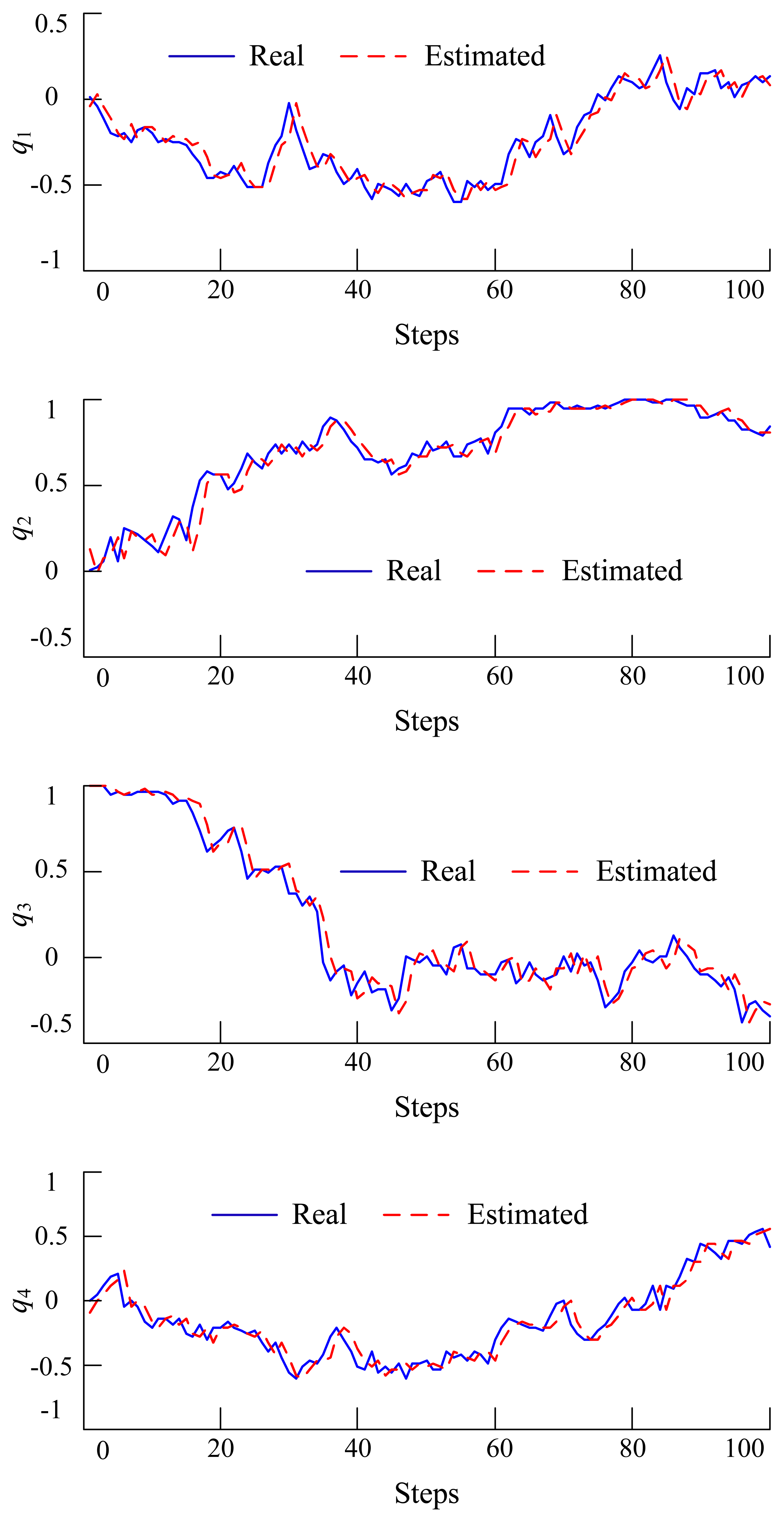
To verify whether the above filtering algorithm will work or not, a simulation in MATLAB has been performed. Additionally, the simulation results are shown in Figure 3, where the solid blue line is the true value, while the dashed red line is the estimated value. From the figure, we can see that the estimated value tracks the true state value very well.
3.3. Swing Angles Calculation
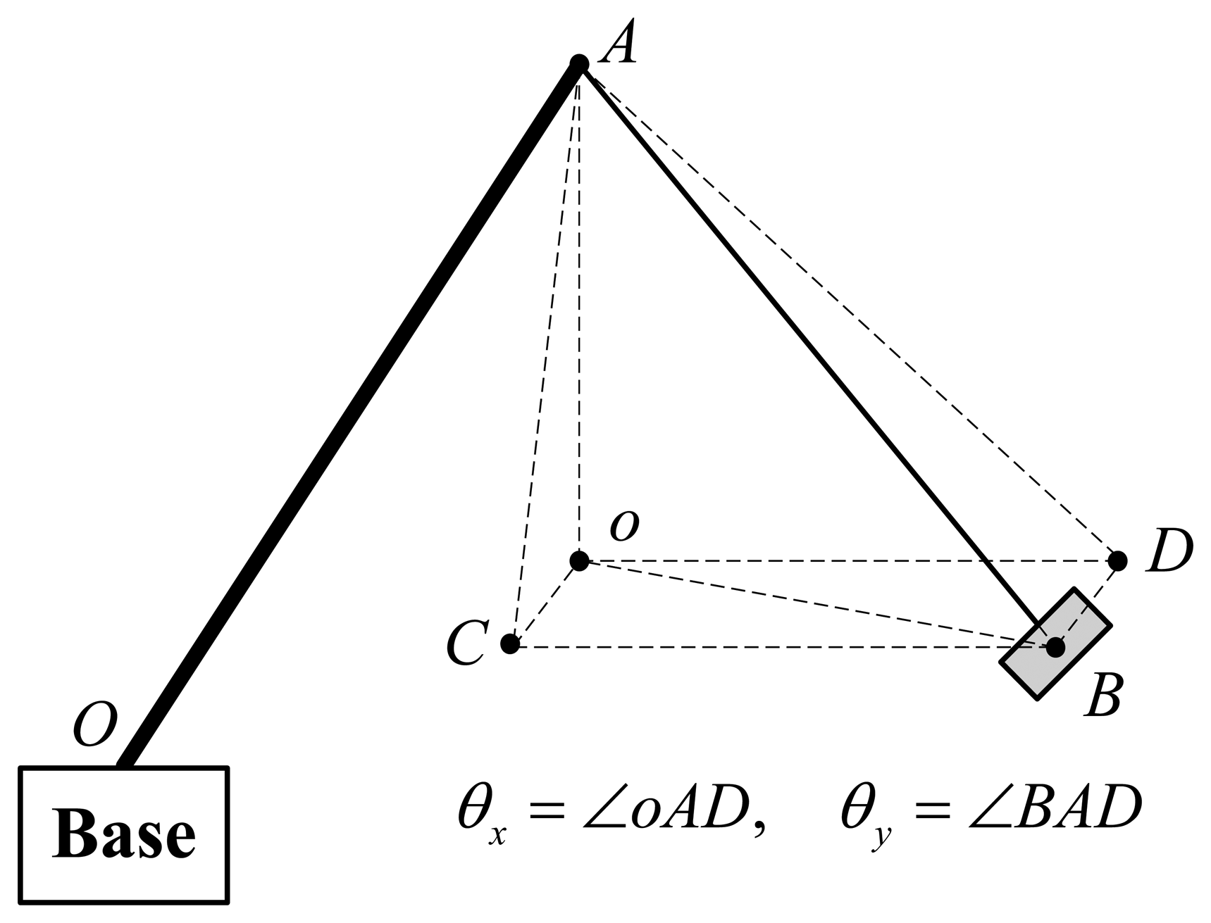
To calculate the swing angles θx and θy, the special case that the payload has no rotation about the rope is considered at first. The geometry description of the swing angles and AHRS angles can be depicted with Figure 4. In Figure 4, plane oCDB is horizontal; point o is the projection of point A (top tip of the jib) on plane oCDB; point B is the center of the payload, as well as the embedded Sensing Unit 2; BC⊥oCA, BD⊥oDA. Therefore, the spatial swing angles can be described as θx = ∠oAD and θy = ∠BAD. There are two assumptions:
- (1)
The rope line of the crane is always vertical to the plane of the payload, as well as the embedded Sensing Unit 2;
- (2)
The payload, as well as the embedded Sensing Unit 2 does not rotate about the rope of the crane.
Based on the above two assumptions, we have ∠oAB = θ, where θ is the pitch angle measured by Sensing Unit 2 and ∠BoD = Δψ where Δψ is the difference of the yaw angle calculated according to the yaw angles measured by Sensing Unit 1 and Sensing Unit 2.
According to the geometric relationship, as shown in Figure 4, we have:
For general cases with pitch, roll and yaw angle (θ, ϕ, ψ) measured by the MEMS-based AHRS sensor embedded in the payload, the special case can be achieved by rotating the AHRS sensor with respect to axis z in the body frame with an angle α. Furthermore, corresponding pitch and yaw angles in the special case are denoted by θ′ and ψ′, respectively The relationship between the general case and special case can be represented with the orientation matrix R(θ, ϕ, ψ) as:
Now, we can calculate the angles θy and θx with Equations (23) and (24) based on the new θ′ and Δψ′ = ψ′ − ψ0, where ψ0 is the yaw angle measured by Sensing Unit 1.
4. Experiments
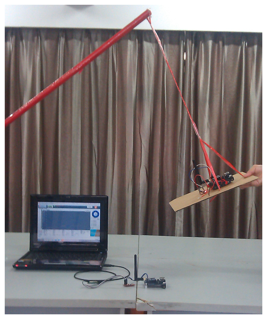
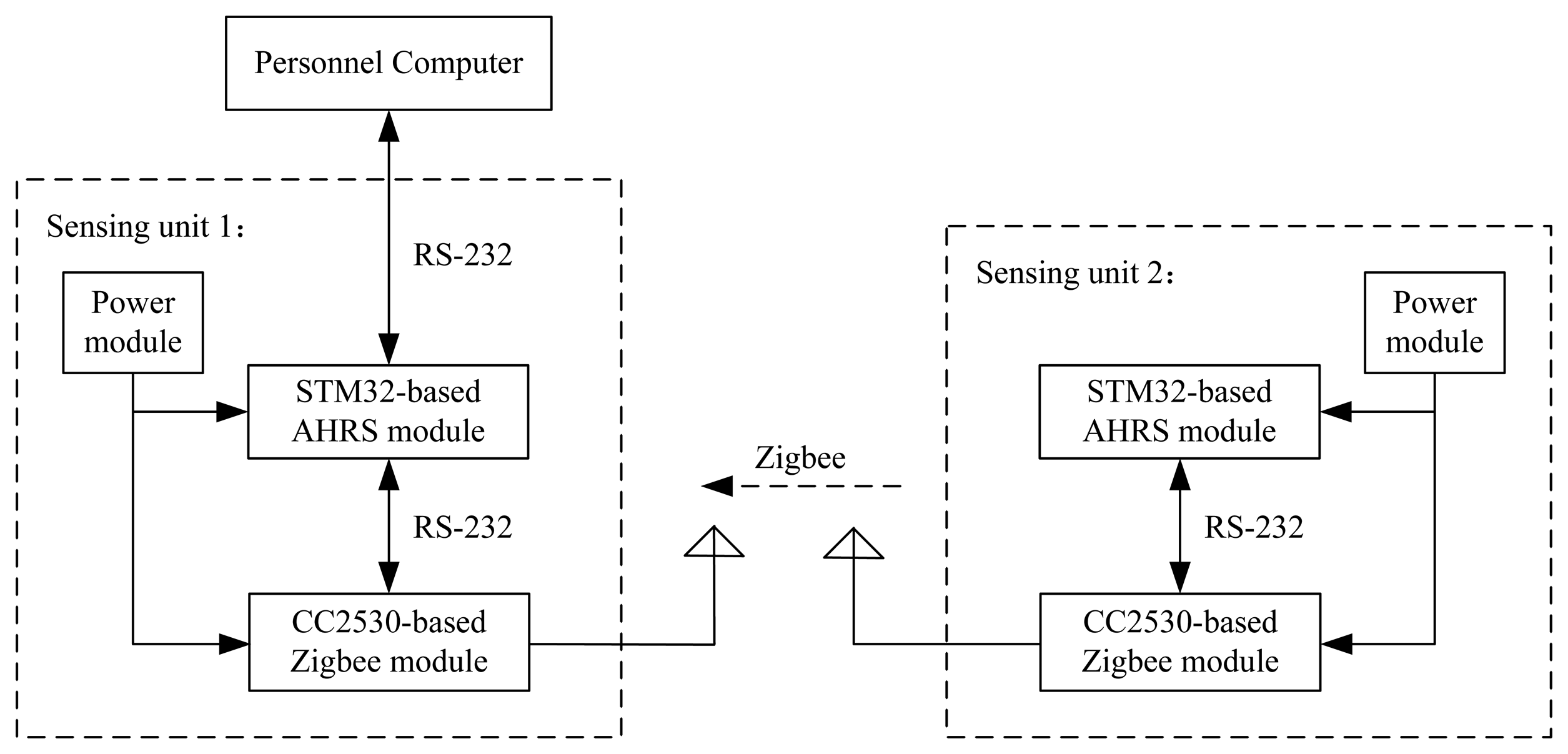
Experiments have been performed to verify the designed swing angle measurement system. A picture of an experiment is shown in Figure 5, and the electrical diagram of the experiment is illustrated in Figure 6. Each sensing unit consists of three main modules, i.e., power module, STM32-based AHRS module and CC2530-based ZigBee module. The STM32-based AHRS module of Sensing Unit 2, as shown in Figure 1, calculated the pitch, roll and yaw angles of the payload in real time based on the algorithms developed in Section 3; and the calculated orientation of the payload is sent to the CC2530-based ZigBee module with serial communication RS-232. The wireless communication module will send the orientation of the payload to Sensing Unit 1, as shown in Figure 1, with the ZigBee communication module. Similarly, the orientation of the crane base is achieved with the STM32-based AHRS module of Sensing Unit 1. Therefore, the swing angles of the payload will be calculated in the STM32-based unit, and then, they will be sent to the control box of the crane with serial communication. As in the experiment, a laptop is used to acquire the angle data and to mimic the control box of the crane system.
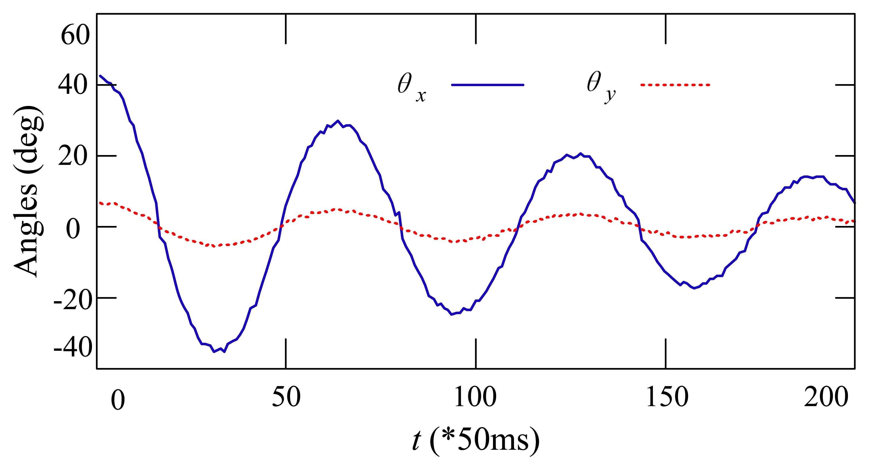
Static and dynamic swing angle measurements based on the developed system were performed. Table 2 shows the static experiment results of the swing angles measurement. During the experiments, the payload was fixed to four typical angles by hand. Comparing the measured results on four typical swing angles of the payload, the measured error increases as the measured angle increases. When the payload has small swing angles, the error of the measured angles is less than one degree. However, when the measured angles become as large as 60 degrees, the measured error is larger than two degrees. The performance of the dynamic angle measurement is shown in Figure 7. During the experiment, the payload was initialized by hand to a random position and then left to swing freely. One can see that the curves of the measured swing angles are smooth and that the swing motion is being damped because of friction.
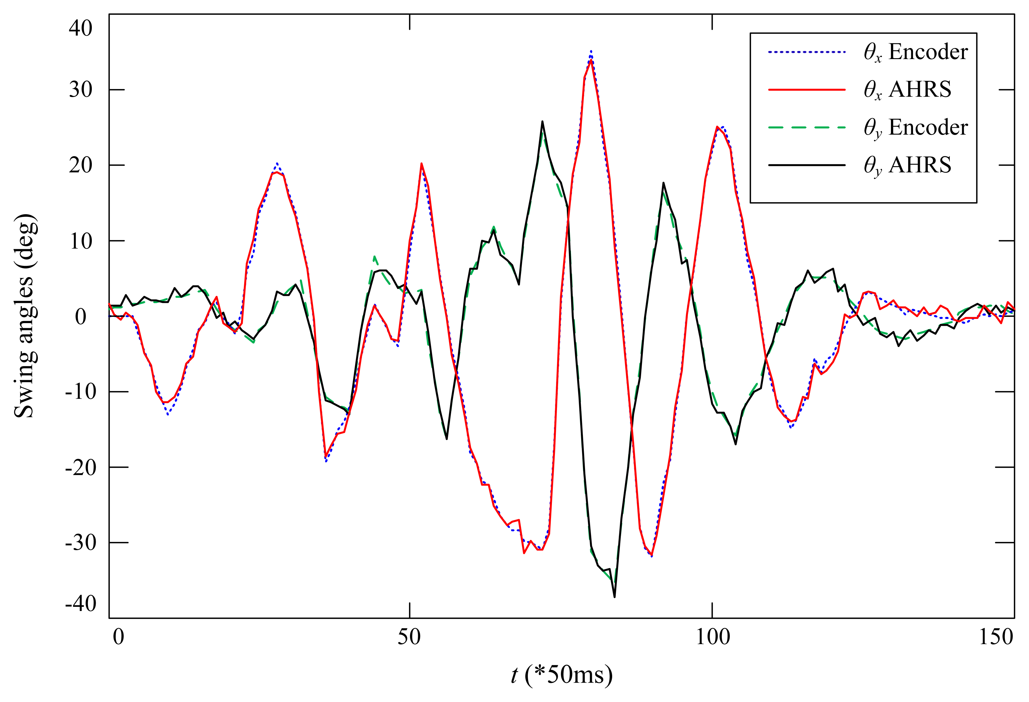
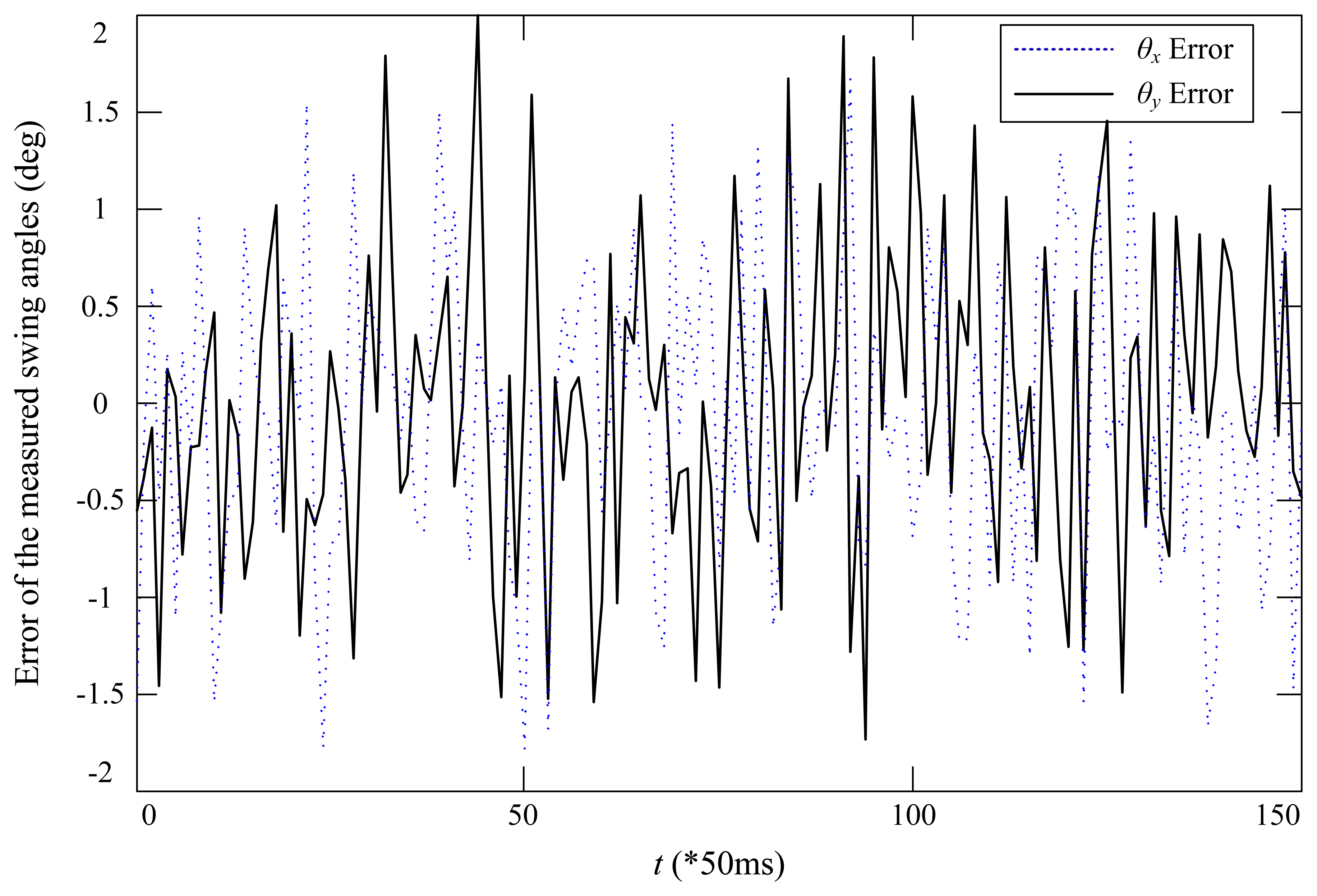
To further examine the accuracy of the developed swing angle measurement system, two high resolution encoders, E6B2-CWZ6C, with 2000 pulses per round from Omron have been used to detect the two angles. The CAD design and the prototype of the encoder-based swing angle measuring mechanism are shown in Figure 8. The payload was moved by hand for several seconds, and the recorded measured angles are shown in Figure 9. One can see that the swing angles measured from the developed AHRS-based wireless scheme using MEMS devices are very close to those measured from the encoders. The displacement errors of the two angles are shown in Figure 10. The mean errors of swing angles θx and θy are both 0.61 degrees; and the maximum errors of swing angles θx and θy are 1.79 degrees and 2.0 degrees, respectively. Although the maximum measuring error is as big as 2.0 degrees by using the developed scheme compared to the encoders scheme, the mean error is steadily around 0.6 degrees, which could be accurate enough for monitoring and anti-swing control in crane systems. Moreover, it is impractical to use the encoder-based scheme in a very large crane system, because additional complicated mechanisms have to be designed and added to the jib of the crane system. However, the developed scheme is low cost and easy to embed in real crane systems.
It should be noted that the mean error of 0.61 degrees was achieved under the lab experimental conditions: around 25 Centigrade, only lights, several computers and one air-conditioning are running. In real industrial environments, the system based on the three MEMS devices should be calibrated in order to obtain the same level of accuracy, because the signals based on these MEMS devices will be disturbed, especially the magnetic signals [30]. Additionally, while transforming the experimental sensing unit to the real environmental implementation, the AHRS module and ZigBee module, as shown in Figure 6, could be redesigned and integrated as one module.
5. Conclusions and Future Work
Measuring the swing angles of different crane systems effectively is helpful to improve the safety and efficiency of the crane systems. The paper proposed a wireless AHRS-based swing angle measurement system by using MEMS devices and ZigBee wireless communication. Preliminary experiments have demonstrated the feasibility of the proposed scheme and confirmed that the mean error of the measured swing angles is no more than 0.7 degrees. Since all of the devices have small dimensions and are low cost, the developed swing angle measurement system is low cost and easy to embed in real crane systems. The wireless feature of the measurement system means that it can be installed conveniently and will not be influenced by the weather environment. Therefore, the developed swing angle measurement system could be widely applied for crane systems.
The experimental results in this paper were achieved in the laboratory. Additionally, the signals of the MEMS devices would be disturbed in real industrial environments. Future work will focus on verifying the scheme in real applications and improving the accuracy of the measurement system.
Acknowledgments
The authors would like to thank the financial support from the National Science Foundation of China (NSFC) (No. 11102039) and the National Student Research Training Program of Southeast University (No. 1410286078).
Author Contributions
Bingtuan Gao contributed to developing the ideas of this research. Bingtuan Gao, Jianguo Zhao and Zhenyu Zhu performed this research. Zhenyu Zhu and Boran Huang performed the experiments. All of the authors were involved in preparing this manuscript.
Conflicts of Interest
The authors declare no conflict of interest.
References
- Gholabi, A.; Ebrahimi, M.; Yousefi, G.R.; Ghayour, M.; Ebrahimi, A.; Jali, H. Sensorless anti-swing control for overhead crane using voltage and current measurements. J. Vib. Control 2013. [Google Scholar] [CrossRef]
- Ngo, Q.H.; Hong, K.-S. Sliding-mode antisway control of an offshore container crane. IEEE/ASME Trans. Mechatron. 2012, 7, 201–209. [Google Scholar]
- Solihin, M.I.; Wahyudi; Legowo, A. Fuzzy-tuned PID anti-swing control of automatic gantry crane. J. Vib. Control 2010, 16, 127–145. [Google Scholar]
- Gao, B.; Lang, Y.; Xing, R.; Zhou, X.; Zhao, J. A Wireless MEMS-Based Swing Angle Measurement System. Proceedings of the 11th World Congress on Intelligent Control and Automation, Shenyang, China, 29 June–4 July 2014; pp. 5872–5876.
- Gao, B.; Chen, H.; Zhang, X.; Qi, H. A Practical Optimal Controller for Underactuated Gantry Crane Systems. Proceedings of the 1st International Symposium on Systems and Control in Aerospace and Astronautics, Harbin, China, 19–21 January 2006; pp. 720–725.
- Singhose, W.; Porter, L.; Kenison, M.; Kriikku, E. Effects of hoisting on the input shaping control of gantry cranes. Control Eng. Pract. 2000, 8, 1159–1165. [Google Scholar]
- Zhang, X.; Gao, B.; Chen, H. Nonlinear Controller for a Gantry Crane Based on Partial Feedback Linearization. Proceedings of the 5th International Conference on Control and Automation, Budapest, Hungary, 27–29 June 2005; pp. 1074–1078.
- Chen, H.; Gao, B.; Zhang, X. Dynamical Modeling and Nonlinear Control of a 3D Crane. Proceedings of the 5th International Conference on Control and Automation, Budapest, Hungary, 27–29 June 2005; pp. 1085–1090.
- Ebrahimi, M.; Ghayour, M.; Madani, S.M.; Khoobroo, A. Swing angle estimation for anti-sway overhead crane control using load cell. Int. J. Control Autom. Syst. 2011, 9, 301–309. [Google Scholar]
- Liu, D.; Yi, J.; Zhao, D.; Wang, W. Adaptive sliding mode fuzzy control for a two-dimensional overhead cran. Mechatronics 2005, 15, 502–522. [Google Scholar]
- Yoshida, Y.; Tsuzuki, K. Visual Tracking and Control of a Moving Overhead Crane Load. Proceedings of 9th IEEE International Workshop on Advanced Motion Control, Istanbul, Turkey, 25–27 March 2006; pp. 630–635.
- Boschetti, G.; Richiedei, D.; Trevisani, A. Delayed reference control for multi-degree-of-freedom elastic systems: Theory and experimentation. Control Eng. Pract. 2011, 19, 1044–1055. [Google Scholar]
- Hyla, P.; Szpytko, J. Vision Method for Rope Angle Swing Measurement for Overhead Travelling Crane—Validation Approach. In Activities of Transport Telematics; Mikulski, J., Ed.; Springer-Verlag: Berlin/Heidelberg, Germany, 2013; pp. 370–377. [Google Scholar]
- Smoczek, J.; Szpytko, J.; Hyla, P. The Application of an Intelligent Crane Control System. Proceedings of 13th IFAC Symposium of Control in Transportation Systems, Sofia, Bulgaria, 12–14 September 2012; pp. 280–285.
- Yu, Y.; Ou, J.; Zhang, C.; Li, L. Wireless Inclinometer Acquisition System for Reducing Swing Movement Control Module Experiment of Hook Model. Proceedings of SPIE—The International Society for Optical Engineering, San Diego, CA, USA, 8 April 2008. [CrossRef]
- Jin, X. Research on acquisition of the cranes swinging angle based on accelerometer. Equip. Manuf. Technol. 2010, 9, 16–20. [Google Scholar]
- Tayebi, A.; McGilvray, S. Attitude stabilization of a VTOL quadrotor aircraft. IEEE Trans. Control Syst. Technol. 2006, 14, 562–571. [Google Scholar]
- Moog Crossbow. Available online: http://www.moog-crossbow.com/products/inertial-products/products-nav440/ (accessed on 9 October 2014).
- LORD MicroStrain. Available online: http://www.microstrain.com/inertial/3DM-GX3-25 (accessed on 9 October 2014).
- VectorNav. Available online: http://www.vectornav.com/vn-100-features (accessed on 9 October 2014).
- Xsens. Available online: http://www.xsens.com/products/mti/ (accessed on 9 October 2014).
- InterSense. Available online: http://www.intersense.com/pages/18/234/ (accessed on 9 October 2014).
- CHRobotics. Available online: http://www.chrobotics.com/shop/orientation-sensor-um6-lt (accessed on 9 October 2014).
- Markley, F.L.; Crassidis, J.L.; Cheng, Y. Nonlinear attitude filtering methods. J. Guid. Control Dyn. 2007, 30, 12–28. [Google Scholar]
- Baerveldt, A.J.; Klang, R. A Low-cost and Low-weight Attitude Estimation System for an Autonomous Helicopter. Proceedings of IEEE International Conference on Intelligent Engineering Systems, Budapest, Hungary, 15–17 September 1997; pp. 391–395.
- Saripalli, S.; Roberts, J.M.; Corke, P.I.; Buskey, G.; Sukhatme, G.S. A Tale of Two Helicopters. Proceedings of IEEE International Conference on Intelligent Robots and Systems, Las Vegas, NV, USA, 27–31 October 2003; pp. 805–810.
- Thienel, J.; Sanner, R.M. A coupled nonlinear spacecraft attitude controller and observer with an unknow constant gyro bias and gyro noise. IEEE Trans. Autom. Control 2003, 8, 2011–2015. [Google Scholar]
- Lee, J.K.; Park, E.J. Minimum-order Kalman filter with vector selector for accurate estimation of human body orientation. IEEE Trans. Robot. 2009, 25, 1196–1201. [Google Scholar]
- Eldredge, A.M. Improved State Estimation For Miniature Air Veicles. Master's Thesis, Brigham Young University, Provo, UT, USA, 2 August 2006. [Google Scholar]
- Harada, T.; Mori, T.; Sato, T. Development of a tiny orientation estimation device to operate under motion and magnetic disturbance. Int. J. Robot. Res. 2007, 26, 547–599. [Google Scholar]


| Symbol | Description |
|---|---|
| θx | planar swing angle describing the far and near swing of a payload |
| θy | planar swing angle describing the left and right swing of a payload |
| θ | general pitch angle |
| ϕ | general roll angle |
| ψ | general yaw angle |
| θ′ | corresponding pitch angle in the special case |
| ψ′ | corresponding yaw angle in the special case |
| Δψ | difference of yaw angles measured by the two sensing units |
| Δψ′ | difference of yaw angles measured by the two sensing units in the special case |
| q | quaternion used to describe the orientation q = [q1,q2,q3, q4]T |
| a | three-axis accelerometer output having three items ax, ay, az |
| h | three-axis magnetometer output having three items hx,hy, hz |
| ω | three-axis gyroscope output having three items ωx,ωy, ωz |
| output of the three-axis accelerometer in the b (body) frame | |
| transformation matrix from the b (body) frame to the l (level) frame | |
| g | gravity constant |
| output of the three-axis magnetometer in the b (body) frame | |
| Hx, Hy | magnetic field along the north and east in the inertial frame |
| x | state vector of a system |
| x | estimated state vector of a system |
| x̂− | propagated states from the prediction step |
| y | output vector of a system |
| u | input vector of a system |
| w | process noise vector of a system |
| v | measurement noise vector of a system |
| Q | covariance matrix of the process noise |
| R | covariance matrix of the measurement noise |
| P | covariance matrix of the state error |
| P− | propagated covariance matrix from the prediction step |
| A | linearization of the state matrix at current estimated states |
| L | Kalman gain |
| C | linearization of the measurement matrix at current estimate states |
| I | identity matrix |
| ao | output of the accelerometer during orientation updating |
| ho | output of the magnetometer during orientation updating |
| ar | reference output of the accelerometer during orientation update |
| hr | reference output of the magnetometer during orientation update |
| va | measurement noise of the accelerometer during orientation update |
| vh | measurement noise of the magnetometer during orientation update |
| R(q) | rotational matrix from body frame to inertial frame in quaternion |
| R(θ, ϕ, ψ) | rotational matrix from body frame to inertial frame in Euler angles |
| Angles (deg) | Real Angle | 0 | 30 | 45 | 60 |
|---|---|---|---|---|---|
| θx | Measured Angle | 0.4 | 28.8 | 46.2 | 62.6 |
| θy | Measured Angle | 0.3 | 29.5 | 44.3 | 61.7 |
© 2014 by the authors; licensee MDPI, Basel, Switzerland. This article is an open access article distributed under the terms and conditions of the Creative Commons Attribution license ( http://creativecommons.org/licenses/by/4.0/).
Share and Cite
Gao, B.; Zhu, Z.; Zhao, J.; Huang, B. A Wireless Swing Angle Measurement Scheme Using Attitude Heading Reference System Sensing Units Based on Microelectromechanical Devices. Sensors 2014, 14, 22595-22612. https://doi.org/10.3390/s141222595
Gao B, Zhu Z, Zhao J, Huang B. A Wireless Swing Angle Measurement Scheme Using Attitude Heading Reference System Sensing Units Based on Microelectromechanical Devices. Sensors. 2014; 14(12):22595-22612. https://doi.org/10.3390/s141222595
Chicago/Turabian StyleGao, Bingtuan, Zhenyu Zhu, Jianguo Zhao, and Boran Huang. 2014. "A Wireless Swing Angle Measurement Scheme Using Attitude Heading Reference System Sensing Units Based on Microelectromechanical Devices" Sensors 14, no. 12: 22595-22612. https://doi.org/10.3390/s141222595