Study on a Two-Dimensional Scanning Micro-Mirror and Its Application in a MOEMS Target Detector

Abstract
:
1. Introduction
2. Two-Dimensional Scanning Micro-Mirror
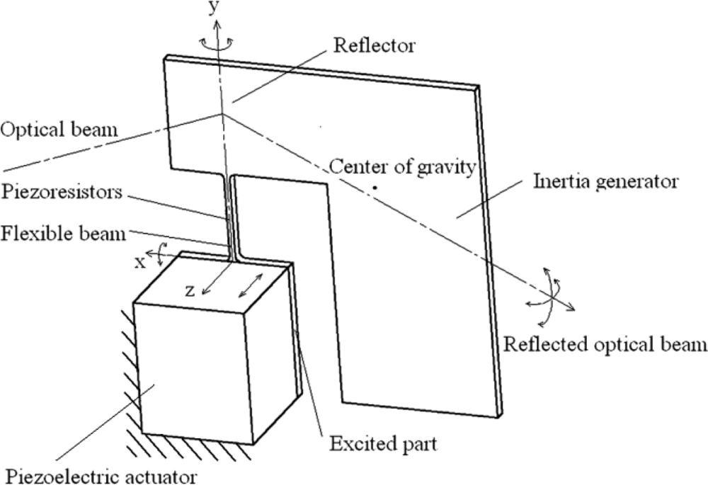
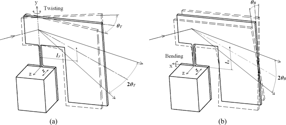
2.1. Structure
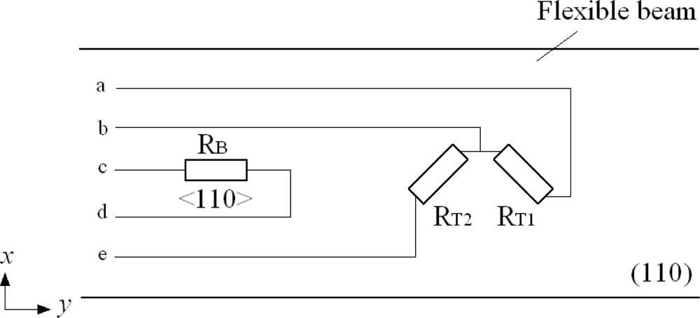
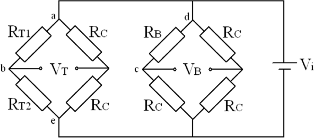
2.2. Piezoresistors
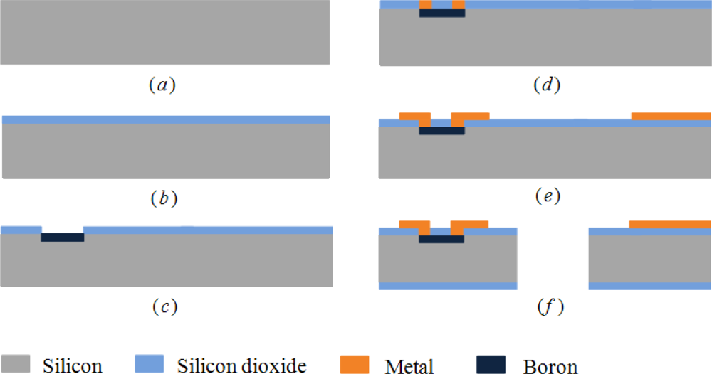
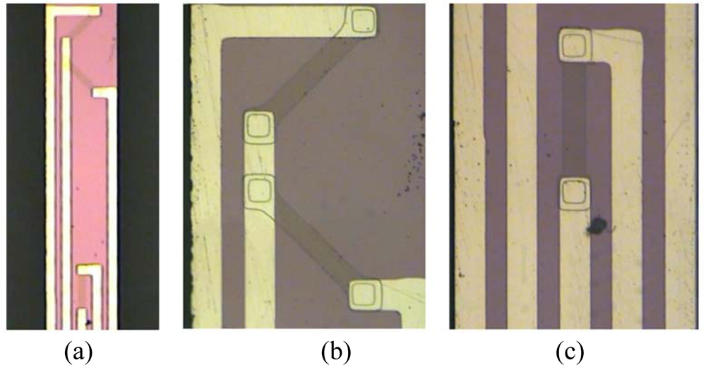
2.3. Fabrication
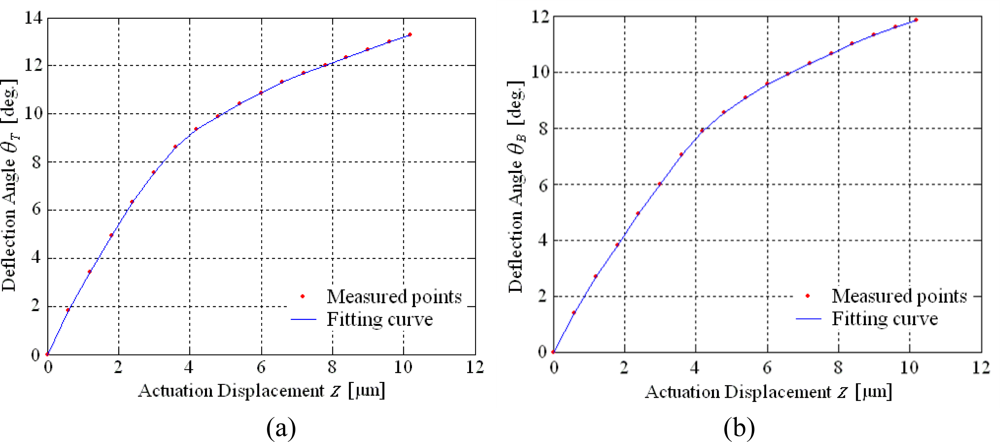
2.4. Characteristics
3. MOEMS Target Detector
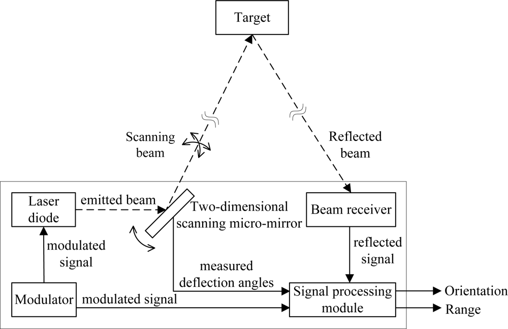
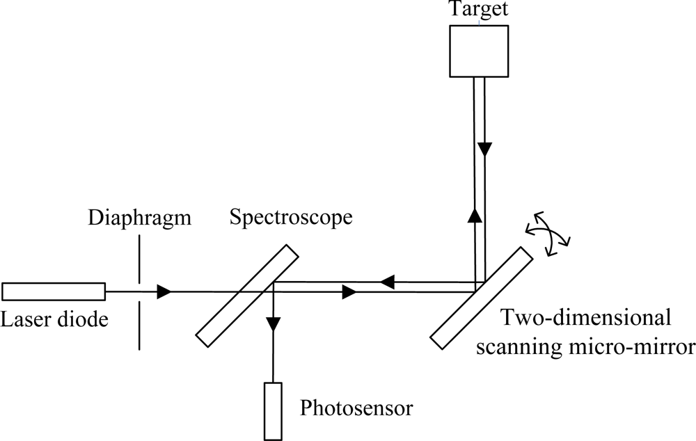
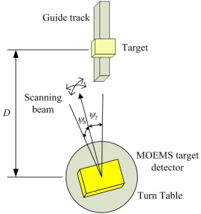
3.1. Structure and Beam Path
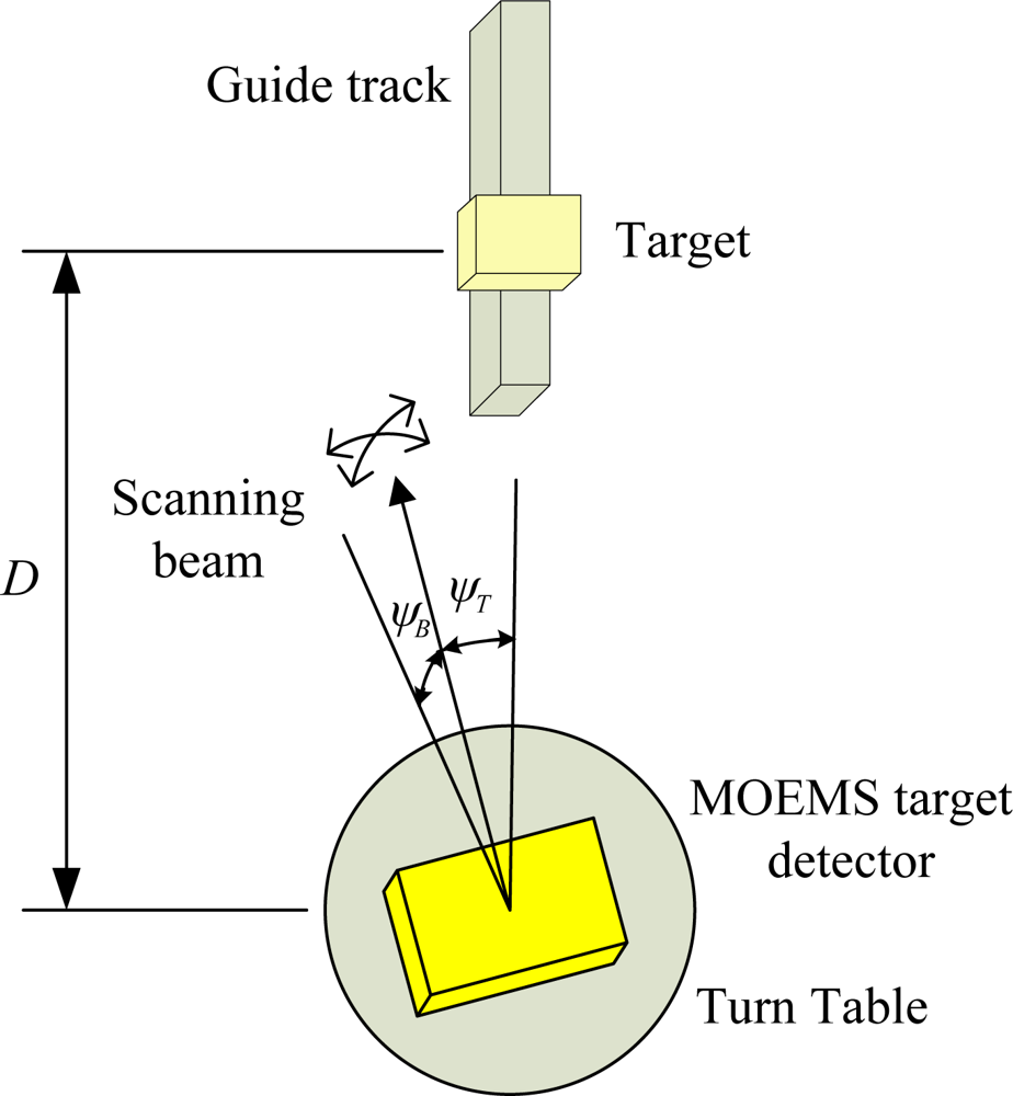
3.2. Target Location Method
4. Experimental Results
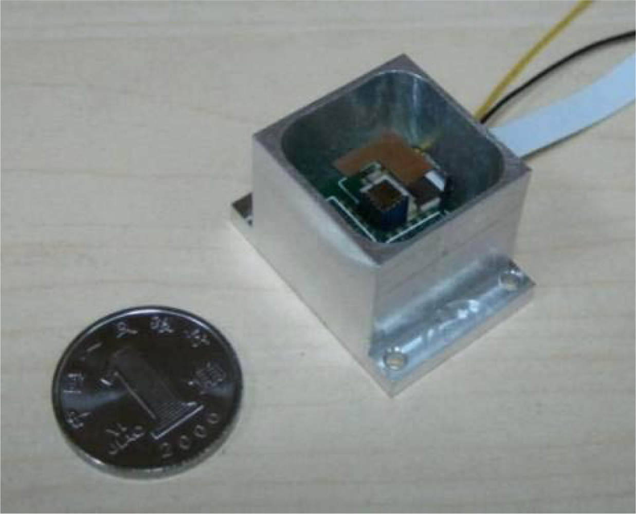
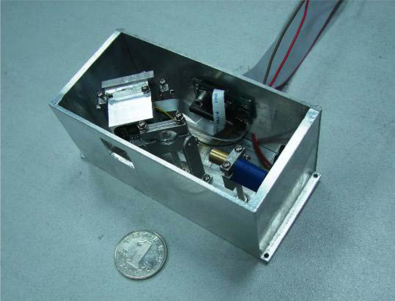
4.1. Detector Prototype
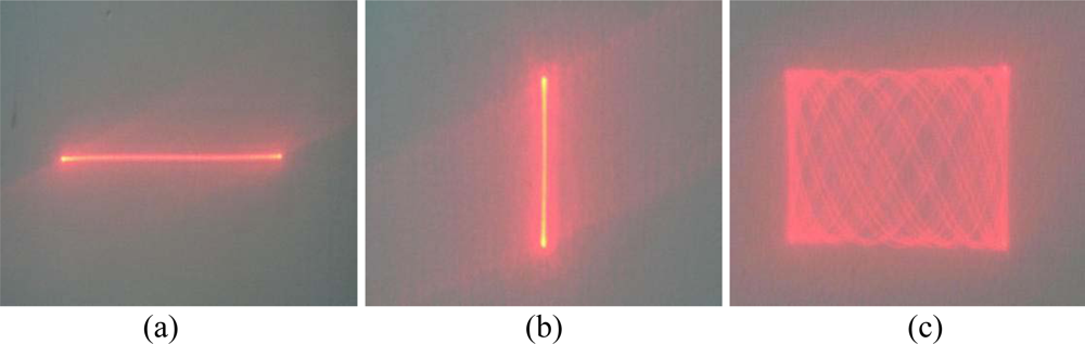
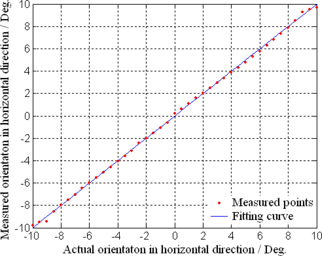
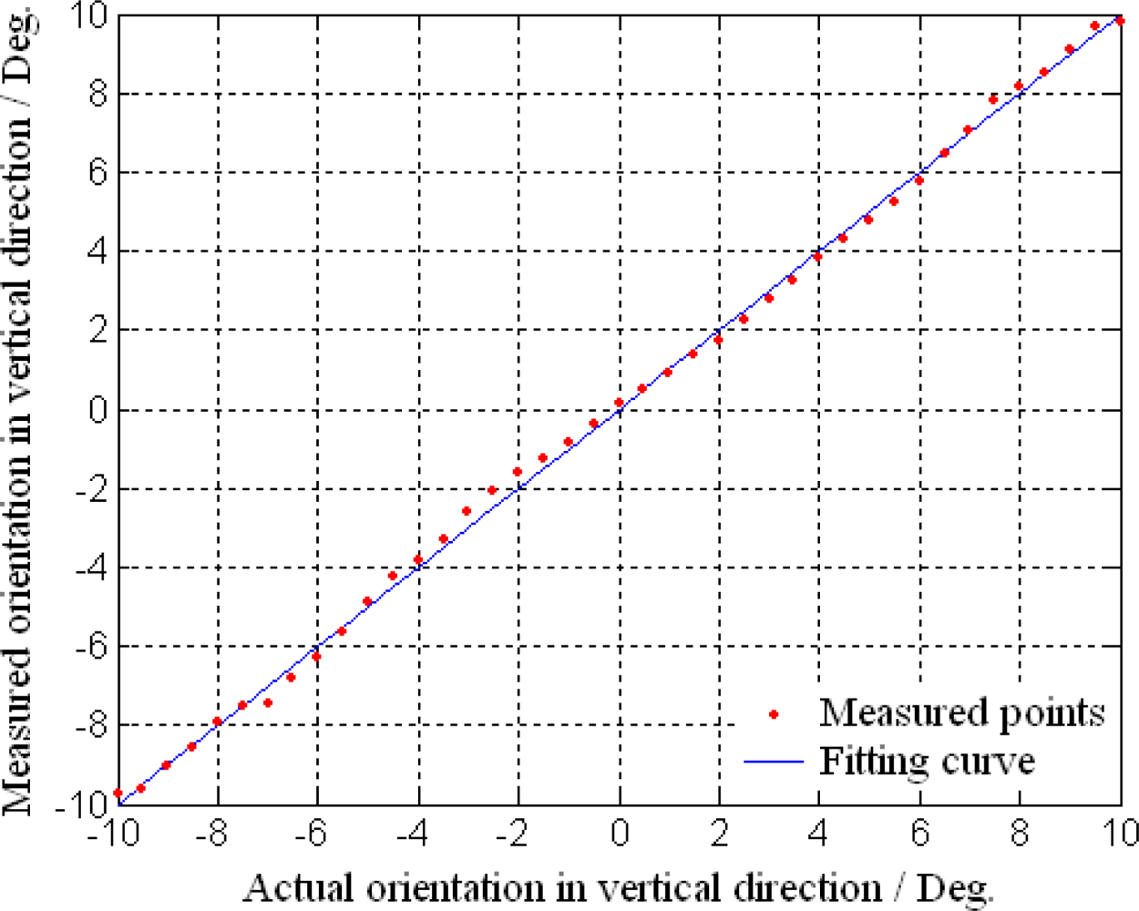
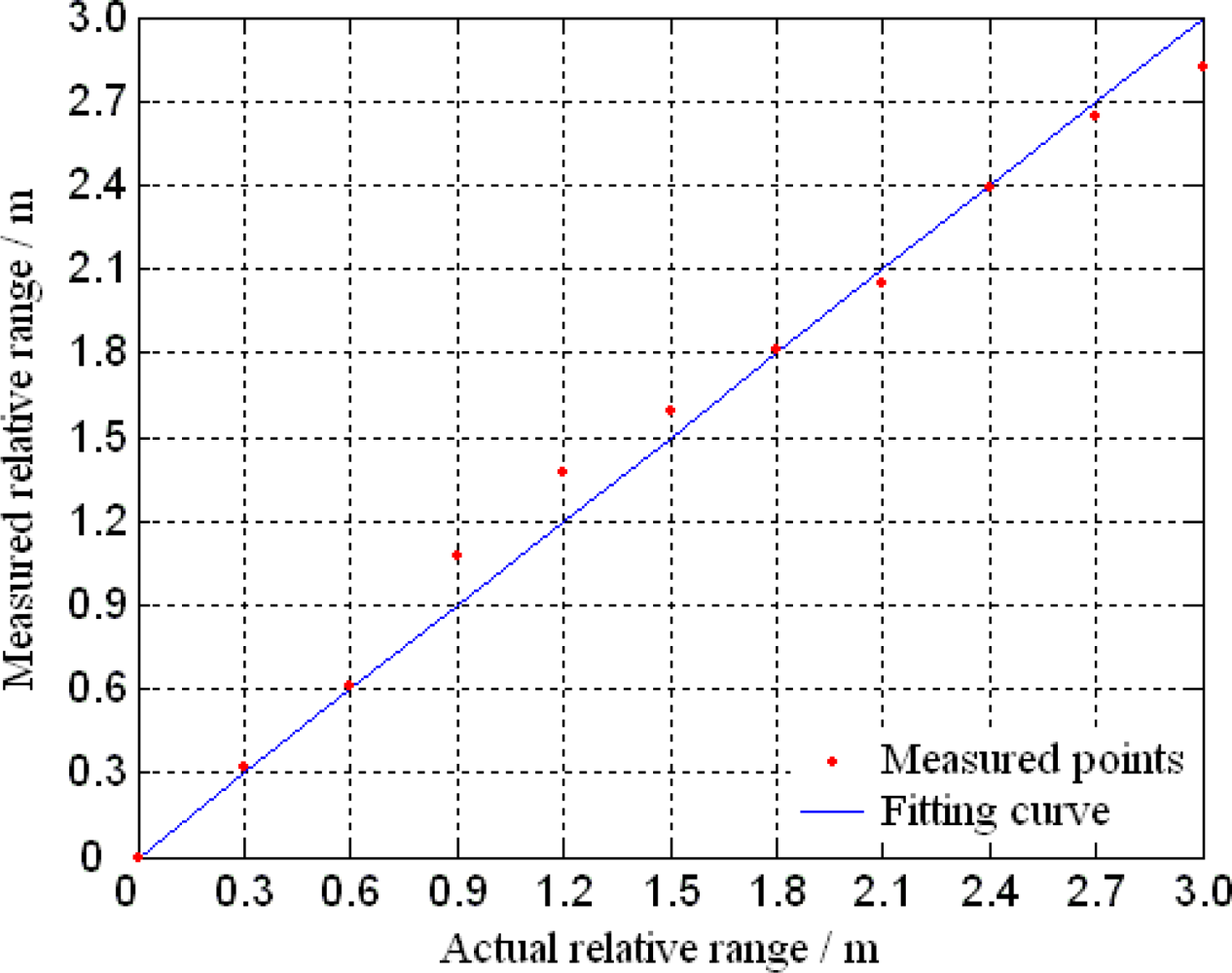
4.2. Target Detection and Location
5. Conclusions
References
- Saito, H; Hashimoto, T; Kasamura, K; Goto, H. Micro-scanning laser range finders and position-attitude determination for formation flight. Proceeding of the 13 Annual AIAA/USU Conference on Small Satellites, Logan, UT, USA, August 23–26, 1999. Report #: SSC99-VI-1.
- Mizuno, T; Mita, M; Takahara, T; Hamada, Y; Takeyama, N; Takahashi, T; Toshiyoshi, H. Two dimensional scanning LIDAR for planetary explorer. Proceeding of CANEUS, Toulouse, France, August 28–September 1, 2006.
- Tsai, JC; Lu, LC; Hsu, WC; Sun, CW; Wu, MC. Linearization of a two-axis MEMS scanner driven by vertical comb-drive actuators. J. Micromech. Microeng 2008, 18, 1–8. [Google Scholar]
- Wolter, A; Schenk, H; Gaumont, E; Lakner, H. Improved layout for a resonant 2D micro scanning mirror with low operation voltages. Proceeding of SPIE-The International Society for Optical Engineering 2003, 4985, 72–82. [Google Scholar]
- Tortschanoff, A; Lenzhofer, M; Frank, A; Wildenhain, M; Sandner, T; Schenk, H; Kenda, A. Position encoding and phase control of resonant MOEMS-mirrors. Procedia Chem 2009, 1, 1315–1318. [Google Scholar]
- Yang, HA; Tang, TL; Lee, ST; Fang, W. A novel coilless scanning mirror using eddy current Lorentz force and magnetostatic force. J. Microelectromech. Syst 2007, 16, 511–520. [Google Scholar]
- Xu, XH; Li, BQ; Feng, Y; Chu, JR. Design, fabrication and characterization of a bulk-PZT-actuated MEMS deformable mirror. J. Micromech. Microeng 2007, 17, 2439–2446. [Google Scholar]
- Lescure, M; Ganibal, C; Prajoux, R; Briot, M. Compact robotics perception system based on a laser range finder coupled with silicon micromirrors. Opt. Eng 2003, 42, 2653–2658. [Google Scholar]
- Miyajima, H; Asaoka, N; Isokawa, T; Ogata, M; Aoki, Y; Imai, M; Fujimori, O; Katashiro, M; Matsumoto, K. A MEMS electromagnetic optical scanner for a commercial confocal laser scanning microscope. J. Microelectromech. Syst 2003, 12, 243–251. [Google Scholar]
- Zhang, C; Zhang, GF; You, Z. A two-dimensional micro scanner integrated with a piezoelectric actuator and piezoresistors. Sensors 2009, 9, 631–644. [Google Scholar]
- Kanda, Y. A graphical representation of the piezoresistance coefficients in silicon. IEEE Trans. Electron. Dev 1982, 29, 64–70. [Google Scholar]
- Zhang, C; Zhang, GF; You, Z. Piezoresistor design for deflection angles decoupling measurement of two-dimensional MOEMS scanning mirror. Proceeding of the 7th IEEE International Conference on Nanotechnology, Hong Kong, China, August 2–5, 2007; pp. 150–153.
- Journet, B; Bazin, G. A low-cost laser range finder based on an FMCW-like method. IEEE Trans. Instrum. Meas 2000, 49, 840–843. [Google Scholar]
- Zhang, C; Zhang, GF; You, Z. Design of space target detection system based on a two-dimensional scanning micro-mirror. Proceeding of the 9th International Conference on Electronic Measurement and Instruments, Beijing, China, August 16–19, 2009; pp. 2718–2721.


| Target location | Horizontal orientation/ Vertical orientation/ Relative range
| |
|---|---|---|
| Actual location | Measured location | |
| P1 | −3° / 2° / 0.4 m | −3.11° / 1.82° / 0.43 m |
| P2 | 0° / 0° / 0.8 m | 0.13° / 0.19° / 0.87 m |
| P3 | 2° / 5° / 1.2 m | 2.00° / 4.84° / 1.37 m |
| P4 | 5° / 0° / 1.6 m | 4.89° / 0.19° / 1.65 m |
© 2010 by the authors licensee MDPI, Basel, Switzerland. This article is an open access article distributed under the terms and conditions of the Creative Commons Attribution license (http://creativecommons.org/licenses/by/3.0/).
Share and Cite
Zhang, C.; You, Z.; Huang, H.; Li, G. Study on a Two-Dimensional Scanning Micro-Mirror and Its Application in a MOEMS Target Detector. Sensors 2010, 10, 6848-6860. https://doi.org/10.3390/s100706848
Zhang C, You Z, Huang H, Li G. Study on a Two-Dimensional Scanning Micro-Mirror and Its Application in a MOEMS Target Detector. Sensors. 2010; 10(7):6848-6860. https://doi.org/10.3390/s100706848
Chicago/Turabian StyleZhang, Chi, Zheng You, Hu Huang, and Guanhua Li. 2010. "Study on a Two-Dimensional Scanning Micro-Mirror and Its Application in a MOEMS Target Detector" Sensors 10, no. 7: 6848-6860. https://doi.org/10.3390/s100706848