Development of a Novel Catalytic Membrane Reactor for Heterogeneous Catalysis in Supercritical CO2


Abstract
:
1. Introduction
2. Experimental Section
2.1. Materials
2.2. Construction of a Catalytic Membrane Flow Reactor
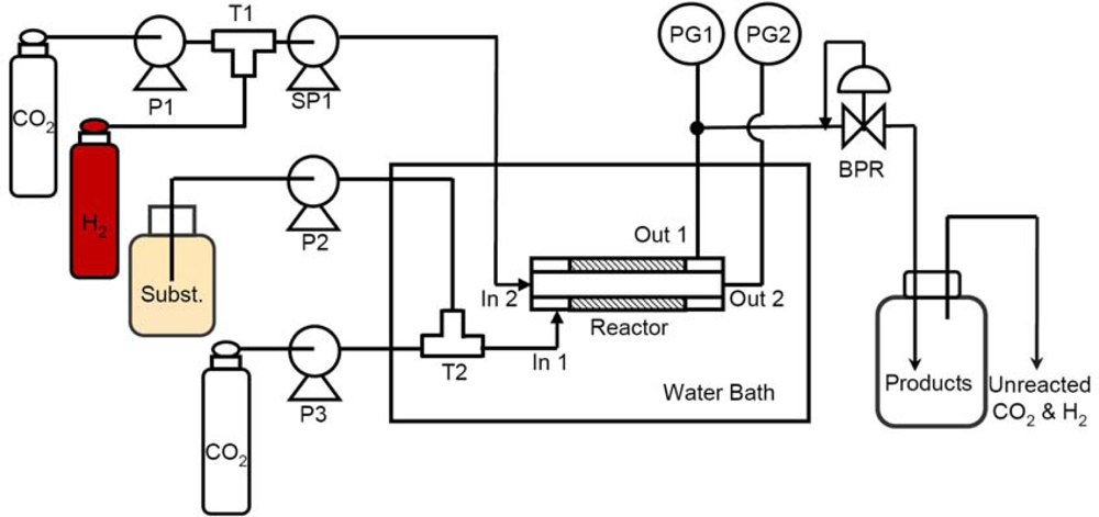
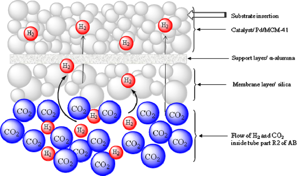
2.2.1. Schematic diagram of the reactor
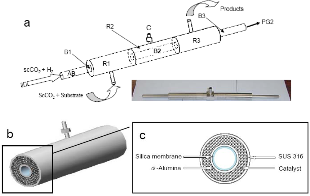
2.2.2. Reaction unit
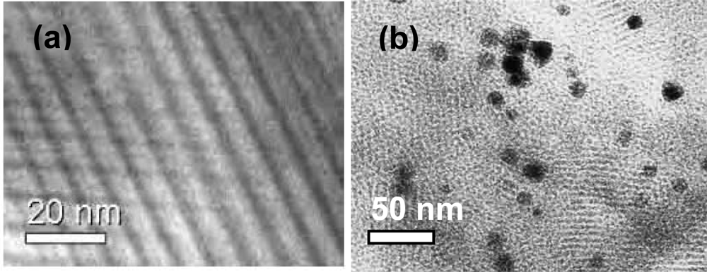
2.1.3. Preparation of the mesoporous silica membrane on α-Al2O3 support
2.1.4. Catalyst synthesis
3. Results and Discussion
3.1. Test of Catalytic Hydrogenation in the CMFR
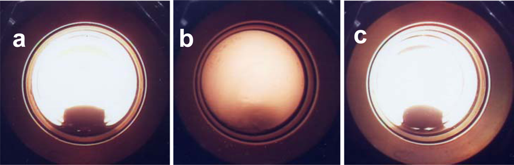
3.2. Phase Diagram
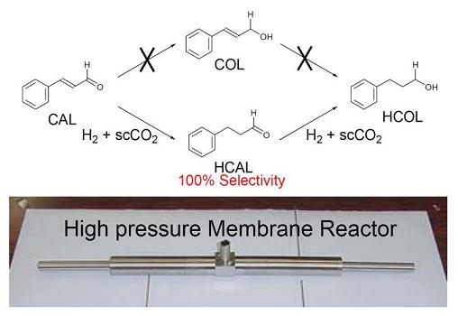
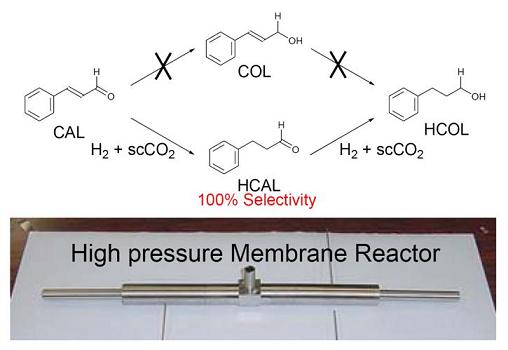
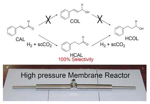
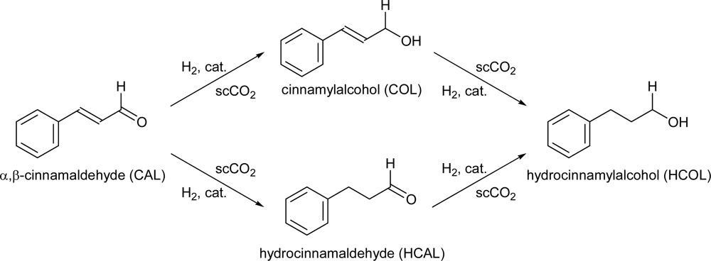
3.3. Test Reaction
4. Conclusions
Acknowledgments
References and Notes
- Johnston, KP; Lemert, RM. Supercritical fluid technology: Theory and application. In Encyclopedia of Chemical Processes and Design; McKetta, JJ, Weismantel, GE, Eds.; Dekker: New York, NY, USA, 1996. [Google Scholar]
- Stephenson, P; Licence, P; Ross, SK; Poliakoff, M. Continuous catalytic asymmetric hydrogenation in supercritical CO2. Green Chem 2004, 6, 521–523. [Google Scholar]
- Van den Broeke, LJP; Goetheer, ELV; Verkerk, AW; Wolf, E; Deelman, B-J; Koten, GV; Keurentjes, JTF. Homogenous reaction in supercritical carbon dioxide using a catalysts immobilized by a microporous silica membrane. Angew. Chem. Int. Ed 2001, 40, 4473–4474. [Google Scholar]
- Turlan, D; Urriolabeitia, EP; Navarro, R; Royo, C; Menendez, M; Santamaria, J. Separation of Pd complexes from a homogeneous solution using zeolite membranes. Chem Commun 2001, 2608–2609. [Google Scholar]
- Nair, D; Scarpello, JT; Vankelecom, IFJ; Freitas, LM; Santos, D; White, LS; Kloetzing, RJ; Welton, T; Livingston, AG. Increased catalytic productivity for nanofiltration-coupled Heck reactions using highly stable catalyst systems. Green Chem 2002, 4, 319–324. [Google Scholar]
- Goetheer, ELV; Verkerk, AW; van den Broeke, LJP; de Wolf, E; van Koten, G; Keurentjes, JTF. Membrane reactor for homogeneous catalysis in supercritical carbon dioxide. J. Catal 2003, 219, 126–133. [Google Scholar]
- Armor, JN. Catalysis with permselective inorganic membranes. Appl. Catal 1989, 49, 1–25. [Google Scholar]
- Bein, T. Synthesis and applications of molecular sieve layers and membranes. Chem. Mater 1996, 8, 1636–1653. [Google Scholar]
- Katsaros, FK; Steriotis, TA; Stubos, AK; Mitropoulos, A; Kanellopoulos, NK; Tennison, S. High pressure gas permeability of microporous carbon membranes. Microporous Mater 1997, 8, 171–176. [Google Scholar]
- Koros, WJ; Mahajan, R. Pushing the limits on possibilities for large scale gas separation: which strategies? J. Membr. Sci 2000, 175, 181–196. [Google Scholar]
- Lee, D; Zhang, L; Oyama, ST; Niu, S; Saraf, RF. Synthesis characterization and gas permeation properties of a hydrogen permeable silica membrane supported on porous alumina. J. Membr. Sci 2004, 231, 117–126. [Google Scholar]
- Kainz, S; Koch, D; Leitner, W; Baumann, W. Perfluoralkylsubstituted arylphosphanes as ligands for homogeneous catalysis in supercritical carbon dioxide. Angew. Chem. Int. Ed 1997, 6, 1628–1630. [Google Scholar]
- Dixon, AG. Recent research in catalytic inorganic membrane reactor. Int. J. Chem. React. Eng 2003, 1, 1–35. [Google Scholar]
- Kang, T; Oh, S; Kim, H; Yi, J. Facile synthesis of mesoporous silica sublayer with hierarchical pore structure on ceramic membrane using anionic polyelectrolyte. Langmuir 2005, 21, 5859–5864. [Google Scholar]
- Chatterjee, M; Iwasaki, T; Onodera, Y; Nagase, T. Synthesis of nanosized platinum cluster in cubic mesoporous material via a direct introduction method. Catal. Lett 1999, 61, 199–202. [Google Scholar]
- Chatterjee, M; Chatterjee, A; Ikushima, Y. Pd-catalyzed completely selective hydrogenation of conjugated and isolated C=C of citral (3,7-dimethyl-2, 6- octadienal) in supercritical carbon dioxide. Green Chem 2004, 6, 114–118. [Google Scholar]
- Burgener, M; Furrer, R; Mallat, T; Baiker, A. Hydrogenation of citral over Pd/alumina: comparison of “supercritical” CO2 and conventional solvents in continuous and batch reactors. Appl. Catal. A: Gen 2004, 268, 1–8. [Google Scholar]


| Entry | PH2 (MPa) | PCO2 (MPa) | Flow CAL mL/min | Time (min) | Conversion (%) | Selectivity (%) | ||
|---|---|---|---|---|---|---|---|---|
| HCAL (%) | COL (%) | HCOL (%) | ||||||
| 1 | 1 | 9 | 0.1 | 30 | 1.2 | 100 | 0 | 0 |
| 2 | 1 | 9 | 0.1 | 60 | 0.3 | 79 | 0 | 21 |
| 3 | 1 | 9 | 0.05 | 15 | 2.7 | 74 | 0 | 26 |
| 4 | 1 | 12 | 0.05 | 60 | 3.3 | 69 | 0 | 31 |
| 5 | 1 | 12 | 0.05 | 60 | 4.5 | 59 | 0 | 41 |
| 6 | 1.5 | 14 | 0.05 | 60 | 5.3 | 58 | 0 | 40 |
| 7 | 1.5 | 16 | 0.05 | 60 | 5.8 | 65 | 0 | 35 |
© 2010 by the authors; licensee Molecular Diversity Preservation International, Basel, Switzerland. This article is an open-access article distributed under the terms and conditions of the Creative Commons Attribution license (http://creativecommons.org/licenses/by/3.0/).
Share and Cite
Islam, N.M.; Chatterjee, M.; Ikushima, Y.; Yokoyama, T.; Kawanami, H. Development of a Novel Catalytic Membrane Reactor for Heterogeneous Catalysis in Supercritical CO2. Int. J. Mol. Sci. 2010, 11, 164-172. https://doi.org/10.3390/ijms11010164
Islam NM, Chatterjee M, Ikushima Y, Yokoyama T, Kawanami H. Development of a Novel Catalytic Membrane Reactor for Heterogeneous Catalysis in Supercritical CO2. International Journal of Molecular Sciences. 2010; 11(1):164-172. https://doi.org/10.3390/ijms11010164
Chicago/Turabian StyleIslam, Nazrul M., Maya Chatterjee, Yutaka Ikushima, Toshiro Yokoyama, and Hajime Kawanami. 2010. "Development of a Novel Catalytic Membrane Reactor for Heterogeneous Catalysis in Supercritical CO2" International Journal of Molecular Sciences 11, no. 1: 164-172. https://doi.org/10.3390/ijms11010164