Review

Molecular Momentum Transport at Fluid-Solid Interfaces in MEMS/NEMS: A Review

1
Key Laboratory for Thermal Science and Power Engineering of Ministry of Education, Department of Engineering Mechanics, Tsinghua University, Beijing 100084, China
2
Institute of Nuclear and New Energy Technology, Tsinghua University, Beijing 100084, China
*
Author to whom correspondence should be addressed.
Int. J. Mol. Sci. 2009, 10(11), 4638-4706; https://doi.org/10.3390/ijms10114638
Submission received: 28 August 2009 / Revised: 17 October 2009 / Accepted: 26 October 2009 / Published: 29 October 2009
(This article belongs to the Special Issue Energy Technology for the 21st Century - Materials and Devices)

Abstract

:
This review is focused on molecular momentum transport at fluid-solid interfaces mainly related to microfluidics and nanofluidics in micro-/nano-electro-mechanical systems (MEMS/NEMS). This broad subject covers molecular dynamics behaviors, boundary conditions, molecular momentum accommodations, theoretical and phenomenological models in terms of gas-solid and liquid-solid interfaces affected by various physical factors, such as fluid and solid species, surface roughness, surface patterns, wettability, temperature, pressure, fluid viscosity and polarity. This review offers an overview of the major achievements, including experiments, theories and molecular dynamics simulations, in the field with particular emphasis on the effects on microfluidics and nanofluidics in nanoscience and nanotechnology. In Section 1 we present a brief introduction on the backgrounds, history and concepts. Sections 2 and 3 are focused on molecular momentum transport at gas-solid and liquid-solid interfaces, respectively. Summary and conclusions are finally presented in Section 4.

Graphical Abstract

1. Introduction

1.1. Backgrounds

As predicted by the famous lecture “There’s Plenty of Room at the Bottom” delivered by Richard P. Feynman at the 1959 annual meeting of the American Physical Society [1], modern nanotechnologies have enabled the fabrication of many micro-/nano-electro-mechanical systems (MEMS/NEMS) with unique attributes, such as small mass, little energy dissipation and high accuracy and sensitivity [29]. Motors, actuators, sensors, reactors, pumps, valves, turbines, engines, etc. at nanometer to micrometer scales have been developed in recent years. Many of these micro-/nanodevices involve fluid and energy transports which are quite different from those at macroscale. Understanding the physics of fluid flows at micro-/nanoscale is crucial to designing, fabricating, utilizing and optimizing these MEMS and NEMS devices [1023].
One of the most important characteristics of fluid flows at micro-/nanoscale is surface-dominated. The surface to volume ratio for a common machine with a characteristic length of 1 m is about 1 m−1, while that for a MEMS device with a size of 1 μm is 106 m−1 and for a NEMS device having a length of 1 nm is 109 m−1. The large surface to volume ratio for MEMS and NEMS devices enables factors related to surface effects to dominate the fluid flow physics at micrometer to nanometer scales [13,14,17,19,21]. Molecular behaviors at fluid-solid interfaces will play a dominant role in micro-/nanoscale mass, momentum and energy transports.
Let’s have a look at a simple example of a plate Poiseuille flow which considers the conventional no-slip and slip boundary conditions (BC) as shown in Figure 1, in which us is the slip velocity defined as the velocity difference between the solid and the fluid adjacent to the wall, Ls is the slip length, and H is the characteristic length of the Poiseuille flow system. The friction coefficient of the plate Poiseuille flow, which characterizes the flow drag, can be written as:
f   =   48 Re 1 1 + 6 L s H
where Re is the Reynolds number [24]. It indicates that the effect of the boundary slip on the friction mainly depends on the ratio of the slip length to the characteristic length of the flow system. The slip length is comparable with the mean free path (MFP) for gases, about 0.065 μm for normal air [25], and is comparable with the molecular diameter for liquids, about 0.29 nm for water. The slip effect at fluid-solid interfaces on the friction can be ignored for macroscopic flows. However, it becomes very important for the micro-/nanoscale flows as the characteristic length decreases.
That is the reason why the present review paper is focused on molecular momentum transport at fluid-solid interfaces. Generally speaking, the boundary slip is only one of the apparent measurements of molecular momentum transport at fluid-solid interfaces, and is often used as boundary conditions for resolving Navier-Stokes (NS) equations. The details of molecular behavior are crucial in understanding flow physics at micro-/nanoscale and resolving particle-based equations in lattice Boltzmann (LB) [26] and direct simulation Monte Carlo (DSMC) [27] methods for modeling fluid mechanics. References [2833] have reviewed the no-slip and slip conditions for liquid flows over solid surfaces. The present review, as a beneficial complement, covers molecular momentum transport at both gas-solid and liquid-solid interfaces, includes more recent achievements, and especially puts more emphasis on molecular behaviors near fluid-solid interfaces.

1.2. History

Studies on fluid mechanics at fluid-solid interfaces can be traced back to the early 19th century [34,35]. As early as in 1823, Navier pointed out that a fluid might slip on a solid surface, i.e., there is a velocity difference, called slip velocity, between the fluid and solid at a fluid-solid interface [36]. He also introduced the idea of ‘slip length’ to quantify the slip boundary condition. Thus, the slip velocity us is linearly related to the slip length Ls and interfacial shear rate by”
u s   =   L s   ( u z ) interface
The linear slip boundary condition, called Navier’s slip model, is nowadays the standard characterization of velocity slip in fluid mechanics. In the following decades, there were debates about whether a fluid slipped on a solid or not. In the 1840s Stokes was commissioned by the Royal Academy of Science to investigate the true nature of the boundary conditions at fluid-solid interfaces and finally supported the no-slip image [37]. Poiseuille [38], Darcy [39] and Helmholtz [40] in their experiments confirmed the slip boundary condition that the velocity of a liquid adjacent to a solid surface was not always equal to that of the surface itself. However, Maxwell then pointed out that their experiments lacked necessary accuracy to distinguish such small slip length from a true no-slip boundary condition [41]. The following experiments offered by Maxwell [41], Whetham [42], Couette [43] and Ladenburg [44] came to the same conclusion that there was no evidence of slip. By the 1900s, though the concept of slip was still obscure, it was accepted that boundary slip, if it did exist, was too small to be observed.
In the mid-20th century there was no believable evidence for the slip at liquid-solid interfaces yet. Bearing in mind that the no-slip concept was doubtable [45,46], most fluid mechanics textbooks accepted the no-slip boundary condition, even without any acknowledgement of its empirical basis [34]. In the late 20th and early 21st centuries the rapid development in nanotechnology enabled more accurate detections and more effective molecular simulations [4751] in fluid mechanics near fluid-solid interfaces. Nanometer scale slip lengths have been observed in recent years. We will review the recent advancements of the experimental and theoretical studies in Section 3.
The history of the study on the momentum transport at gas-solid interfaces is quite different compared with that at liquid-solid interfaces. In 1879 Maxwell [52] proposed a slip expression for gases over a solid surface based on kinetic theory:
L s   =   2 σ t σ t λ
in which σt is the tangential momentum accommodation coefficient (TMAC), i.e., the fraction of molecules reflected diffusively from a solid surface, and λ is the mean free path of the gas molecules. In 1909 Knudsen did the first experiment and confirmed the Maxwell slip model [53]. In the following decades the Maxwell model was demonstrated to be valid for gases over solid surfaces by the Boltzmann transport theory [5456] and experimental measurements [5761]. The Maxwell model has been widely used in rarefied gas dynamics and gas microfluidics thus far. In recent years different slip models, such as higher order and nonlinear models, and various technologies for determining TMAC, which characterize molecular behaviors near gas-solid surfaces in more detail, have been developed. This is just what we will focus on in Section 2.

1.3. Molecular Momentum Transport and Boundary Conditions at Fluid-Solid Interfaces

The momentum transport for molecules near a solid surface is in a nonequilibrium state as shown in Figure 2. The layer in a nonequilibrium state is about a mean free path in thickness adjacent to a solid surface. In rarefied gas dynamics this layer is often called Knudsen layer [57,6264]. The incident molecules to the solid surface have a macroscopic velocity ui. During the collisions with the surface, the molecules will lose a fraction of the tangential momentum. Thus the reflected molecules have a different macroscopic velocity uo. uiuo because there are nearly no collisions between the incident and reflected molecules in this layer. The mean velocity of the incident and reflected molecules, i.e., the fluid velocity, is (ui + uo)/2. uo can approach zero if the reflected molecules lose all their tangential momentum during the collisions with the solid surface. Even for this extreme case, the fluid velocity near the solid surface is uo/2, not zero. It is indicative of a velocity slip for fluids flowing over a solid surface.
We often use three kinds of boundary conditions in micro/nanofluidics: no-slip, slip and effective (apparent) slip as shown in Figure 3: (a) No-slip: There is no velocity difference between the fluid and the wall at their interfaces. It remains an empirical assumption in classical fluid mechanics because early experiments were in good agreement with this boundary condition according to the foregoing review. (b) Slip: There is a velocity difference between the fluid and the wall at their interfaces, which can be characterized by the Navier’s linear slip model. It should be noted that the Navier’s model can be used only outside of the Knudsen layer. In the Knudsen layer Boltzmann transport equation has to be applied. (c) Effective (apparent) slip [31]: The effective (apparent) slip, being negative, zero or positive, is an equivalent concept of the macroscopic measurement of drag, force or flow rate etc. in experiments or simulations. Thus the effective slip is not an intrinsic slip but frequently used in hydrodynamics at liquid-solid interfaces. It may arise from the averaging effects of surface wettability, fluid viscosity, surface roughness, gas bubbles and other factors.

2. Gas-Solid Interfaces
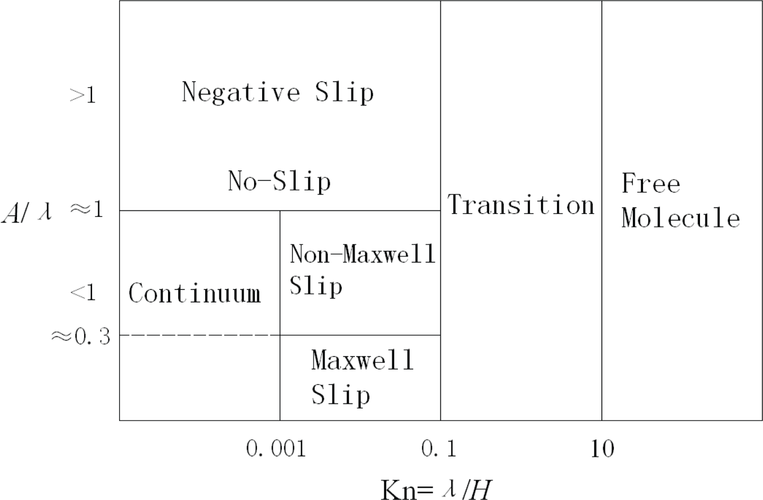
The Boltzmann equations are usually good enough to describe the motions and interactions of gas molecules, especially for the rarefied gases since the gas density is much lower than the liquid density. The Knudsen number (Kn), which is defined as the ratio of the mean free path to the characteristic size in gas flows, is the dimensionless number to characterize the rarefaction:
Kn   =   λ H
in which λ is the mean free path of gas molecules, and H is the characteristic size in gas flows.
The gas-solid momentum transport is affected by both the interactions between nearby gas molecules (gas-gas interactions) and the interactions between gas molecules and solid atoms (gas-solid or gas-wall interactions) near the solid surface. The rate of momentum transport varies for different Knudsen numbers due to the change of relative importance of gas-gas and gas-wall interactions. According to the dimensionless Boltzmann equation [65], the intermolecular force weakens gradually at larger Knudsen numbers. The gas flows are generally divided into four regimes according to the Knudsen number [66]:
Kn < 0.001Continuum regime
0.001< Kn < 0.1Slip regime
0.1< Kn < 10Transition regime
Kn > 10Free molecular regime
When Kn is smaller than 0.001, the Navier-Stokes equations with no-slip boundary condition are applicable. Seen from the definition in Equation (4), a larger Kn may arise from a longer mean free path, i.e., rarefied gas flows, or a smaller system size, i.e., microscale and nanoscale gas flows. When Kn is large, slip phenomena, e.g., the velocity slip and temperature jump, appear in the thin gas layer adjacent to the solid wall, which is named as the Knudsen layer. Several papers, based on the Boltzmann equations [67], described the fluidics in Knudsen layer and found that its thickness was 0.9 to 4.9 times of the mean free path [6872]. Inside the Knudsen layer, the momentum transport in high Kn flows is different from that in low Kn flows in two aspects [17,73]. In rarefied gas flows, where the mean free path is much larger, the continuum assumption is not valid; while for gas flows in microchannels and nanochannels, parameters related to wall effects become dominated since the ratio of area to volume is large. Therefore, proper models have to be applied to describe gas-wall interactions in high Kn flows. In the slip regime with moderate Knudsen numbers, the NS equations are also valid but slip boundary conditions should be taken into account. For larger Kn, the NS equations break down, and the Boltzmann equations or methods based on the kinetic theory should be applied. In this case, the Maxwell-type model or Cercignani-Lampis-Lord model are often used at the boundary [27,68].
In such boundary slip models, the accommodation coefficients are necessary inputs to characterize the gas-solid momentum transport. The tangential and normal momentum accommodation coefficients (abbreviated as TMAC and NMAC) are usually used to characterize the momentum exchanges parallel and perpendicular to the surface. Indeed, the early researches on gas-wall interactions were only focused on determining the accommodation coefficients in these boundary slip models [74]. Furthermore, the study of the accommodation coefficients also helps understanding the gas-solid momentum transport by investigating the velocity distributions of impinging and reflected gas molecules.
In the following sections, molecular motion is primarily introduced through various models. Then, the authors focus on the research on tangential momentum transport, including slip models and the TMAC. At last, some promising problems are discussed for further studies.

2.1. Description of Molecular Distributions

In researches on gas-wall interactions, theoretical models have been developed to show the velocity distribution relation between the incident and reflected gas molecules. Thus, the tangential and normal momentum transport can be expressed explicitly in such models.
The first and most fundamental description of gas-wall interactions was proposed by Maxwell in 1859 [75]. The gas-wall interactions were divided into two processes: incidence and reflection. In kinetic theory, Maxwell established two classical reflection models, i.e., the diffusive and specular models. In the diffusive model, gas molecules are adsorbed near the wall for a long time and totally forget the incident information. After that, these molecules are desorbed and re-emitted to the half space above the wall in all angles equiprobably. The tangential momentum is completely lost and the normal momentum changes to fixed values related to the wall temperature (see Equation 35) in diffusive reflections. In the specular model, where gas molecules experience direct elastic collisions with the wall without adsorption, the tangential momentum holds and the normal momentum only changes the direction.
The diffusive model is widely used in practical applications, especially in macroscale and engineering problems, in which the adsorption time is also usually much longer than that in rarefied gas flows or in flows on extremely smooth surfaces. Under conditions where the adsorption time is not extremely long or short, the diffusive or specular model alone is not appropriate. Maxwell [52] combined the diffusive and specular models together, named Maxwell-type model, that one fraction of molecules are diffusively reflected while the other are specularly reflected. The combination of the two models makes the Maxwell-type model to be a single-parameter model, which can not describe the momentum and energy transport at the same time. Furthermore, the fraction of diffusively reflected molecules is an empirical parameter and difficult to be determined because it strongly depends on many physical factors at the gas-solid interfaces. Many researchers treated it as the TMAC in order to calculate the tangential momentum transport, while used the energy accommodation coefficient (EAC) for the energy transport. However, in most cases, the TMAC and EAC are not equal in the same problem. Moreover, the single parameter cannot describe the momentum transport in both the tangential and normal directions. In addition, the Maxwell-type model is only applicable for the gas flows where the rarefaction and roughness effects are not evident.
According to the reciprocal law, Cercignani and Lampis [76] developed a phenomenological model (CL model) to describe gas-wall interactions, in which two parameters related to the tangential momentum and normal energy transport were introduced. Later, Lord [77,78] modified and extended the CL model (named as CLL model) in the direct simulation Monte Carlo method (DSMC) [27] and made it widely used in theoretical and numerical researches of rarefied gas flows. The CLL model improves the velocity distributions of reflected gas molecules and agrees well with the lobular distribution but does not agrees well with the results observed by molecular beam experiments [79].
There are also some models describing the gas-wall interactions by fitting with the experimental results based on introducing some empirical parameters, in which the Nocilla model and multi-flux model are two of the most typical ones. In the Nocilla model [80,81], the reflected speed ratio, reflection angle and some other parameters can be well selected so as to agree with the computational results [82]. Nevertheless, Collins and Knox [83] implied that two parameters in this model could not be chosen arbitrarily and were related to the TMAC and NMAC. In the multi-flux model [84], the phase space of incident molecules is divided into several regimes according to the incident velocities and angles. By the combination of the diffusive model and CLL model with different possibilities, the multi-flux model can be also comparable with other models by selecting proper possibilities, but it is too specific for practical applications.
Since the interactions at the gas-solid interfaces are complicated and strongly depend on the surface conditions, models with limited parameters cannot fully describe the reflection of gas molecules yet. The multi-stage model [79], based on molecular dynamic simulations, could determine the information of reflected gas molecules in three stages. Using the multi-stage model, the DSMC results agreed well with the molecular beam experiments and improved the CLL model significantly.
From the above review of models about gas-wall interactions, the descriptions of reflected gas molecules by the surfaces are not good enough due to the complicated situations at gas-solid interfaces. More parameters are required to be added into the models and more realistic models have to be established in the future.

2.2. Tangential Momentum Transport

Besides the descriptions of molecular distributions, models and parameters of macroscopic properties are usually concerned in researches of momentum transport, especially in tangential momentum transport. Tangential momentum transport is one of the most important points because it is often related to flow resistance on surfaces, mass and volume flow rates, as well as pressure drop in channels and tubes. The velocity profiles inside the Knudsen layer also drew much attention. Many experts tried to employ slip models as boundary conditions in resolving the NS equations and extended the applicability of the NS equations to larger range of Knudsen numbers. In addition, the TMAC is also the key input in the slip models.

2.2.1. Slip Models

Since the Knudsen layer is only several mean free paths in thickness, there are very few gas molecules in this thin layer, and the continuum hypothesis is not valid. As the Knudsen number increases, the Knudsen layer gradually extends from near-surface to the main flow so that the NS equations with traditional no-slip boundary conditions are not proper to describe the slip phenomena for large Kn. Higher order equations should be used, such as the Burnett equations [85], super-Burnett equations [86], Grad 13 moment method [72] and normalized Grad moment methods [87], but there are still many problems in the boundary conditions and computational stability. The Boltzmann equations are good enough for rarefied gas flows, while the direct solutions of the Boltzmann equations are much limited due to the strong nonlinear collision term. Moreover, the atomic simulations (molecular dynamics or Monte Carlo method) can trace the molecular motions and obtain more detailed results. However, the computation power of computers is not strong enough, and the space and time scales in atomic simulations are confined in small systems and time ranges. Therefore, in order to describe the phenomena inside the Knudsen layer, a more practical and compromise way is to find appropriate boundary models to extend the applicability of the NS equations. And it has been reported that the NS equations with modified slip models showed good results in the slip regime of 0.001 < Kn < 0.1.
As a common phenomenon in tangential momentum transport, the velocity slip can be described by models based on and developed from the Maxwell-type model. Maxwell [52] assumed that one half of the gas molecules near the wall are incident and the other half are reflected, in which one part of them is diffusive while the rest is specular. Using Taylor series and omitting high order terms, the famous Maxwell first-order slip model is:
u s   =   2 σ t σ t λ d u d z | w
where us is the velocity slip on the wall surface, i.e., the difference between gas velocity adjacent to wall and the wall velocity, σ t denotes the TMAC at the wall, 2 σ t σ t is generally named the slip coefficient and is usually studied along with the TMAC together [88], and d u d z | w is the normal gradient of gas velocity at the wall. In addition, velocity slip is also affected by thermal creep or thermal transpiration, which is not considered in isothermal flows in this review.
From Equation (5), the velocity slip is related to the TMAC, the mean free path or Knudsen number, the velocity gradient above the wall, and their combination or expression. Therefore, researches on slip models always concern on the accuracy of these parameters and reasonable expressions.
Slip models can be divided into two categories: the linear and nonlinear models. The Maxwell model of Equation (5) is the earliest and most widely used linear slip model, in which the velocity slip is proportional to the mean free path and the constitute relation is linear. Researches on linear slip models are all based on and developed from the Maxwell model, and care about the magnitude and expression of the slip coefficient [66,68,75,8993]. While in nonlinear slip models, the constitute relations are nonlinear and the velocity slip is no longer linear with the mean free path.

2.2.1.1. Linear Slip Models

In slip models, the velocity slip is proportional to the mean free path and velocity gradient. In other words, the constitute relation is linear. Besides the Maxwell first-order expression in Equation (5), the linear slip models are usually used in a second-order form:
u s   =   C 1 λ d u d z | w     C 2 λ 2 d 2 u d z 2 | w
in which C1 and C2 are first- and second-order slip coefficients, respectively. For Maxwell model in Equation (5), C 1   =   2 σ t σ t and C2 = 0.
Research on linear slip models is concerned with the slip coefficients in two aspects: their magnitudes when σt =1 and their expressions, especially in the form of the TMAC. When σt =1 for the diffusive boundary condition, the first- and second-order slip coefficients from literature are listed in Table 1, in which the results are not consistent. The first-order slip coefficients are almost around unity while the second-order slip coefficients range from −0.5 to larger than one. In experiments, the second-order slip coefficients being derived from mass flux would be underestimated for about 0.3 without considering the effect of the Knudsen layer [93]. For instance, Maurer et al. [94] tested the gas flows in microchannels and found that the second-order slip coefficient for N2 was 0.26 ± 0.1, while Sreekanth [95,96] gave 0.14.
The investigation on the expression of slip coefficients is much difficult, and most expressions are based on the Maxwell model, as shown in Table 2. The first-order slip coefficients are related to the TMAC while the second-order slip coefficients are quite different.
In linear slip models, the velocity slip is linear with the mean free path, in which the mean free path is constant along the channel’s height between two walls. The NS equations with linear slip models cannot describe the flow inside the Knudsen layer accurately, especially for large Kn gas flows, as shown in Figure 4. For the region far from the wall, the velocity profile predicted by NS equation with linear slip models agrees well with the results by the kinetic theory or DSMC method. While in the near wall region, the velocity profile predicted by the NS equations is different from that by the kinetic theory inside the Knudsen layer, and the velocity slip predicted by linear slip models (uNS , also called fictitious velocity slip [102]) is larger than that by the kinetic theory (uactual, the actual velocity slip). Schram [103] deduced that u N S   =   2 u a c t u a l. If the velocity profile inside the Knudsen layer is truly obtained by modifying the slip coefficients in linear slip models, the velocity profile outside is not accurate any more [66,93,100]. Therefore, the linear slip models can only applicable for low Kn gas flows (Kn < 0.1) where the effect of the Knudsen layer reduces to a small region adjacent to the wall.

2.2.1.2. Nonlinear Slip Models

Since the linear slip models ignore the wall effects on the mean free path and velocity profiles, the description of the Knudsen layer must be more accurate using nonlinear slip models, in which the velocity slip is not proportional to the mean free path any more. In nonlinear slip models, the constitutive relations are modified so that the stress is expressed in a more realistic way. The mean free path is also modified by effective expressions.
By replacing the viscosity (μ) and the velocity gradient (shear rate) in Equation (5) with the tangential stress (τ) [52,100]:
τ   =   μ u z
The velocity slip related to the stress is:
u s   =   2 σ t σ t λ τ μ
In complicated situations, the stress is not as simple as that in Equation (7). Lockerby et al. [100] revealed that the normal velocity of near-wall gas changed along the wall when the wall was not flat or the wall moved in the normal direction. The velocity slip in the tangential direction was affected by both the tangential and normal velocity and expressed as:
u s   =   2 σ t σ t λ ( u x z + u z x )
in which ux and uz are, respectively, gas velocities in the tangential and normal directions. The prediction of the Couette flow between two coaxial cylinders could be improved by using the slip model of Equation (9) and agreed well with the DSMC results [100]. Einzel et al. [104] also setup a slip model considering the surface roughness above the wall.
In planar flows, Lockerby et al. [102] established the constitutive relation according to the wall function in turbulent flows and the solution to the linearized Boltzmann equation [68]:
τ   =   μ ( 1 + 7 10 ( 1 + z λ ) 3 ) 1 d u d z
in which z denotes the distance from the wall. The corresponding slip model is:
u s   =   2 π 2 σ t σ t λ τ μ
In Equation (10), the constitutive relation can be expressed by using the effective viscosity (μeff) shown in Equation (12), in which the effective viscosity is apparently position-related and affected by the wall:
μ eff   =   μ ( 1 + 7 10 ( 1 + z λ ) 3 ) 1
The effective viscosity in Equation (12), fitted from the velocity profile near the wall, is not physically meaningful in further applications for the mean free path or the thermal conductivity [105,106]. Reese et al. [105] continued to use the scaled constitutive relation to extend the NS equations, and the stress and effective viscosity are:
τ   =   μ [ 1 A ( D σ t + E ) ( 1 + z ^ ) A 1 ] 1 d u d z ^
μ eff   =   μ   [ 1 A ( D σ t + E ) ( 1 + z ^ ) A 1 ] 1
in which z ^   =   π 2   z λ is the reduced distance from the wall, parameters A , D and E are calculated from resolving the Boltzmann equation using the hard sphere or the Bhatnagar-Gross-Krook (BGK) models [107]. Thus, the slip model is:
u s   =   2 σ t σ t   ζ λ   τ μ
in which ζ is about 0.8 and is close to 2 / π in Equation (11).
Following the first-order scaled constitutive relation of Equation (15), which was well applied in Kramer’s problem, Lockerby et al. [108] established a second-order scaled constitutive relation to simulate gas flows on sphere surfaces, and the slip model is:
u s   =   0.798 λ τ μ 0.278 λ 2 μ d τ d z
Besides the investigations on various constitutive relations, Stops [109] analyzed the space distribution of the mean free path between two parallel walls and introduced the notion of effective mean free path (λeff) as:
λ eff   =   λ 0 { 1   +   1 2 [ ( a     1 ) e a   +   ( b     1 ) e b     a 2 E i   ( a )     b 2 E i   ( b ) ] }
a   =   z / λ 0
b   =   ( H     z ) / λ 0
E i ( x )   =   1 t 1 e x t d t
in which λ0 is the mean free path of gas flows with no bounding wall, z is the distance from the wall, and H is the distance between two separated walls. For different Kn, the wall effect on the mean free path is quite different, and the Knudsen layers enlarge from the near wall region and may overlap for large Kn, as shown in Figure 5.
In kinetic theory, the mean free path is related to the viscosity for equilibrium rarefied gases by [68]:
λ   =   μ p π R T 2
If this relation is also valid for the effective mean free path and effective viscosity [110112] in constant pressure (density) isothermal gas flows, the effective viscosity is:
μ eff   =   λ eff p π R T 2
μ eff   =   μ 0 { 1 + 1 2 [ ( a 1 ) e a + ( b 1 ) e b a 2 E i   ( a ) b 2 E i   ( b ) ] }
in which μ0 is the viscosity without the wall effect.
Guo et al. [113] applied the effective viscosity of Equation (23) to the NS equations so that the isothermal Couette and Poiseuille flows can be described as:
d d z ( μ eff   d u d z )   =   0
d d z ( μ eff   d u d z ) + ρ g x   =   0
in which gx is the driving acceleration in isothermal Poiseuille flows. According to the effective mean free path in Equation (17), Guo et al. [110] setup a second-order slip models as below, and extended the applicability of the NS equations to higher Kn (up to about 4) gas flows, in which the mass flux agreed well with experimental results in Refs. [114,115]:
u s   = C 1 ( λ eff   d u d z ) | w     C 2 [ λ eff   d d z ( λ eff   d u d z ) ] | w
C 1   =   2 σ t σ t ( 1 0.1817 σ t )
C 2   =   1 π   +   1 2 C 1 2
Arlemark et al. [111,112] used Simpson’s numerical integration involving several subintervals to replace the exponential integral in Equation (20) and obtained the similar results as Stops’ in Ref. [109]. Furthermore, Arlemark et al. [111,112] compared the velocity profiles predicted by the linearized Boltzmann equations with that by the NS equations through altering the slip coefficients in Equation (26), and found the best slip coefficients for Kn < 0.113 were C1 = 1 in first-order slip models while C1 = 0.05 and C2 = 0.63 in second-order slip models.
The nonlinear flows inside the Knudsen layer are still difficult to describe, whether for the constitutive relations or for the effective mean free path and viscosity. The constitutive relations from the numerical results of the Boltzmann equations are often lack of physical explanations, and the relation between the effective mean free path and viscosity are not valid when the density (pressure) are not constant in the microchannels [116,117]. Therefore, researches on nonlinear slip models, especially for large Kn gas flows, are still challenging.

2.2.2. TMAC

In aforementioned slip models, the TMAC is one of the most important parameters to characterize the tangential momentum transport between the gas and wall. The momentum accommodation coefficients were first proposed by Knechtel and Pitts [118] to investigate the surface gas dynamics in free molecular flows. The TMAC is recently studied in slip and transition flow regimes [88] as required in microfluidics and nanofluidics.
The TMAC is defined as the ratio of the actual rate of tangential momentum transfer from the gas to the surface to that when gas molecules striking the surface are re-emitted as if from a gas in equilibrium at the surface temperature, and the definition is:
σ t   =   p t i p t r p t i p t w
in which the subscript t denotes the tangential component, p is the average momentum of gas molecules, i and r represent the incident and reflected gas molecules, and w is the average parameter for those molecules who are diffusively reflected from the wall. For the wall moving at the velocity of uw , we have:
p t w   =   m g u w
in which mg is the mass of a gas molecule.
Since the information of the incident and reflected molecules is unknown in most cases, the TMAC is not easily predicted by theories so that the TMAC is usually obtained from experiments or numerical simulations [88]. The TMAC is quite sensitive to the gas-solid interface conditions. The impact factors on the TMAC usually include the gas-solid pairs and their interaction potentials, varieties of surface conditions such as temperature, absorbents, lattice configurations, and surface roughness. The TMAC is widely used in theoretical and practical situations and empirically chosen as unity. However, under the conditions of high temperature, high vacuum, clean surface or high speed, the TMAC is no longer unity [119,120].

2.2.2.1. Experiments on TMAC

In molecular beam experiments [121,122], the incident angle and incident energy of gas molecular beams on test surfaces are fixed. The reflected distribution is gathered and both the TMAC and NMAC can be extracted with some of the results listed in Table 3. In the gas dynamics of aircrafts or space shuttles [123], the incident gas flows orient in fixed angles to the surface, and the results from the molecular beam tests are often applicable. The measured results were sometimes called beam accommodation coefficients [74]. While for gas flows in channels or tubes, the angle and energy of incident gas molecules are usually in random distributions. Thus, beam accommodation coefficients are different from those in channel or tube flows [124,125].
Since the tangential momentum exchange at gas-solid interfaces is often related to flow resistance, mass flux and slip in gas flows, experimental technique, such as the spinning rotor gauge method and flow in microchannels, were used to measure the TMAC, which have been reviewed in detail by Agrawala and Prabhu [88].
In the spinning rotor gauge method with the results listed in Table 4, a magnetized steel sphere is suspended and spinning at a high speed [129]. When the driving force is off, the sphere gradually slows down by the gas around and the TMAC can be obtained by recording the angular velocity and pressure [130,131]. Comsa et al. [132], Gabis et al. [133], Tekasakul et al. [134], Bentz et al. [135,136] and Jousten [137] have used the spinning rotor gauge method to test many monatomic and polyatomic gases as well as mixed gases on the steel surface. The method was modified by Bentz et al. [138] to unite the calculation model and experimental setup. As a result, the recalculated TMAC for He and Ar decreased by about 15% [134]. Lord [88,127] also used the similar method and found that the TMAC for He and Ar on the Mo surfaces were 0.20 and 0.67, while for surfaces with adsorbents, the TMAC was 0.9.
In microchannels, the TMAC is generally obtained by measuring the mass flux based on the slip models [66,139]. Arkilic et al. [140] found that the TMAC was about 0.8 in silica microchannels. Colin et al. [141], Hsieh et al. [142], Jang and Wereley [143,144] reported on the effects of surface roughness on the average TMAC in silica and glass microchannels. Jang and Wereley [144] further derived the relation between the averaged TMAC and the TMAC for different wall species. In addition, Huang et al. [145] used the pressure sensitive paint to measure the pressure distribution in microchannels. Copper et al. [146] studied Ar, N2 and O2 flows in carbon nanotubes and obtained same TMAC for these gases. In Blanchard and Ligrani’s experiments [147], the TMAC decreased rapidly with the increasing surface roughness on the spinning disk. Since the slip coefficients and slip models are still not consistent [66,68,88,99], the TMAC calculated according to different slip models may be different.
There are also some other methods to investigate the TMAC. In the rotating cylinder method, the Couette flows in the polar coordinate are driven by a rotating inner cylinder and a still outer cylinder, which are coaxial. When the torque is measured, the TMAC can be calculated according to the slip models [148]. Millikan [57] and his students Stacy [149] and van Dyke [58] have done many experiments to measure different TMAC for various gases on the oil surfaces in the slip flow and transition flow regimes. Kuhlthau [61] also tested the air flow and its flow resistance on Al surfaces, and the TMAC for slip flow and transition flow regimes were 0.94 and 0.74 processed by Agrawal and Prabhu [150]. Recently, Maali and Bhushan [151] performed an experimental measurement of the slip length of air flow close to glass surfaces using an atomic force microscope in dynamic mode and found that the slip length was 118 nm and the TMAC was about 0.72 with the Knudsen number varying from 0.01 to 10.
Suetin et al. [152] and Porodonov et al. [153] calculated the TMAC by measuring the relation between the relaxation time of pressure difference and the pressure in non-steady flows [88]. Shields [154156] studied the acoustic velocity for low pressure gases and calculated the TMAC according to the relation between the acoustic velocity and velocity slip. Gronych et al. [157] used the viscosity vacuum gauge to measure the relative TMAC for different gas species.
The TMAC obtained from these methods mentioned above are listed in Tables 46 for brief comparison considering the effects of temperature and Knudsen number. The results reveal that the TMAC is quite sensitive with the surface conditions and is significantly affected by the experimental methods and surface conditions [158,159].

2.2.2.2. Simulations on TMAC

As reviewed by Gak-el-Hak [13,167], the numerical means to simulate gas flows can be divided into continuum and molecular methods. The numerical methods based on the Boltzmann equations [68], the DSMC method [27,168,169] and lattice Boltzmann method (LBM) [170173] all need given boundary conditions. The MD method [48] based on the first principle can simulate detailed gas-wall interactions if given the intermolecular potentials. Therefore, pure MD method or MD method coupled with other methods [119,174180] are proper for studying the gas-solid momentum exchange and the accommodation coefficients.
Chirita et al. [181] used the Lennard-Jones (LJ) potential to simulate the incident Ar molecules on the Ni (001) surface. Various incident angles and incident energies were selected to investigate the gas molecular motions and reflected distributions near the wall. Chirita et al. [182] further calculated the accommodation coefficients considering the temperature effects. Finger et al. [183] compared the behaviors of reflected gas molecules with the experimental results by Seidl and Steinheil [126], and found that the TMAC was larger than unity due to the backscattering phenomenon as well as the effects of the adsorbent layers. Arya et al. [184] changed the characteristic parameters in the LJ potential to calculate the effects on the accommodation coefficients in channels. Celestini and Mortessagne [185] also simulated the Knudsen diffusion process and found that the TMAC for single molecule colliding with the wall was inversely proportional to the mean collision numbers. In these MD simulations, only the gas-wall interactions are considered and the gas-gas interactions are neglected, thus, these results are proper for highly rarefied gas flows.
Yamamoto and his collaborators [119,174177] used the DSMC method to simulate the main flow in the center of nanochannels and the MD simulations to treat the gas-gas and gas-wall interactions near the walls. The effects of temperature, surface roughness and adsorbed molecules on the accommodation coefficients were investigated. Cao et al. [186] compared the velocity profiles of isothermal flows in MD simulations with the analytical solutions of the NS equations with the Maxwell slip boundary condition to extract the TMAC and found the temperature dependence of the TMAC. Spijker et al. [187] used the MD method to test different boundary models and calculated the accommodation coefficients in thermal conductions. Sun and Li combined the effects of temperature and adsorbed layers on the TMAC [188] and calculated the accommodation coefficients for various wall lattice configurations in smooth channels and in rough channels with nanoscale roughness. All the MD results are listed in Table 7.
According to the definition of the TMAC, one of the most important points to calculate the TMAC is to distinguish between the incident and reflected gas molecules in MD simulations. Chirita et al. [181] setup the escape plane in the distance of 2.36σgs (length parameter for gas-wall interactions in the LJ potential) from the wall and recorded the information of reflected molecules on the escape plane, while Arya et al. [184] used 3.0σgs. Yamamoto [119] calculated the accommodation coefficients at 8σs (length parameter for Pt wall atoms in the LJ potential) from the wall when the gas molecules enter or leave the MD domain. Spijker et al. [187] set the virtual border at 2.5σg (length parameter for gases in the LJ potential) from the wall. Sun and Li defined the incident and reflected gas molecules according to the cutoff radius in MD simulations and found that the TMAC was independent of the cutoff radius when it is larger than 3σg.
Although the experimental and numerical researches of the TMAC have been in progress for about 50 years, the effects of many physical factors on the TMAC are still obscure. Taking the effect of Knudsen number for an example, Yamamoto et al. [177] studied the N2 gas flows in Pt nanochannels and found that the TMAC decrease with increasing Kn when there were Xe molecules adsorbed on the Pt surfaces, while the TMAC did not change on smooth surface. In gas flow experiments in microchannels, Arkilic et al. [140], Maurer et al. [94] and Hsieh et al. [142] also predicted the decreasing TMAC with increasing Kn. In the spinning rotor gauge method, Gabis et al. [133] indicated that the TMAC for He, Ne, N2, CH4 and C2H6 decreased for larger Kn, but for Ar, the TMAC decreased in the slip regime while increased in the transition regime. However, in experiments by Ewart et al. [166], the TMAC for Ar were almost the same for different Kn ranges. Agrawal and Prabhu [88] recommended 0.926 for monatomic gases for the entire range of Kn in their review, but it was not suitable for diatomic and other gases.
When the Knudsen number varies, the relative importance of the gas-gas and gas-wall interactions changes according to the Boltzmann equations [65,68]. Although Eckert and Drake [189] indicated that the results in the slip flow and free molecular flow regimes were relevant, the effects of Knudsen number on the tangential momentum transport were still not clarified from the above references. In addition, the selection of the value of the TMAC in slip models still depends on experience because the TMAC is quite sensitive to the surface conditions.

2.3. Research Insufficiency

2.3.1. Non-Maxwell Reflections

From the previous two sections, the phenomena at gas-solid interfaces are so complicated because of the effects of many factors. The existing models of gas-wall interactions are incapable of describing the gas-solid transport for many non-Maxwell reflections arising from the surface roughness [190198] and adsorbed layers above the wall.
The slip length is no longer linear with the mean free path when the surface roughness becomes larger above the wall, and the ratio of the roughness A to the molecular mean free path, A/λ, is a good criterion to use the slip boundary condition along with the NS equations. In addition, the roughness on the wall often leads to the gas molecules more accommodated with the wall so that the TMAC increases with the increasing roughness [188]. On the basis of the kinetic theory of gases, the interaction of gas molecules and a wall in the Maxwell theory is primarily based on the assumption of bounce-back behaviors, which is a linear combination of the diffusive and specular reflections. This assumption may be valid only for mathematically smooth walls. However, when the surface roughness is comparable with the molecular mean free path, this assumption is no longer rigorous. From molecular simulations [191,197,198], the backwater gases beneath the roughness interspace may play an important role in the momentum exchange between gases and solid surfaces, because the molecules impinging the backwater may undergo multicollisions inside the roughness interspace. Thus, the Knudsen layer and the wall roughness overlap. This means that the molecules can penetrate through the wall boundary region, which is quite different from an imaginary mathematically smooth surface. The molecular behaviors combining multi-collisions and permeability are responsible to the surface roughness induced non-Maxwell slippage. Regimes depending on both Knudsen number and the surface roughness can be re-categorized as in Figure 6 [197,198].
The gas molecules are easier to be adsorbed near the wall under conditions where the temperature is low [186] or the gas-wall interactions are strong [117]. When more and more molecules are adsorbed and molecular layers are formed near the walls, the molecular behaviors are consequently changed, and the momentum transport at gas-solid interfaces is dominated by both the gas-gas and gas-wall interactions. Sun and Li [117] found that the TMAC decreased with the increasing temperature for less adsorption, while the TMAC was almost independent of the temperature for quite strong gas-wall interactions.
Recently, Sokhan and Quirke [199] showed that the slip length depends strongly on the pore width for small pores tending to a constant value for pores of width larger than 20 molecular diameters for their systems, in contrast to the linear scaling predicted by Maxwell’s theory of slip. Calculating the slip length should require two material parameters: shear viscosity, which could be taken from the bulk equation of state for the viscosity, and relaxation time, which was a function of the thermodynamic state of the liquid and also depended on the pore dimensions. In these cases, the gas-solid momentum transport cannot be described by the classical Maxwell model, and more accurate boundary models are needed.

2.3.2. Normal Momentum Transport

Compared with the tangential momentum transport, few researches were focused on normal momentum transport. For instance, there are many kinds of definitions for the NMAC [82,83,127, 200206] as follows, which characterize the normal momentum transport at gas-solid interfaces:
σ n   =   p n i p n r p n i p n w   =   | p n i |   +   | p n r | | p n i |   +   | p n w |
σ n   =   | p n i |     | p n r | | p n i |     | p n w |   =   p n i + p n r p n i + p n w
σ n   =   | p n i |     | p n r | | p n i |   =   p n i   +   p n r p n i
σ n   =   p n i     p n r p n i   =   | p n i |   +   | p n r | | p n i |
in which i , r and w are the same as those in the TMAC definition, and n denotes the normal component of momentum. And when the wall temperature is Tw, we have:
p n w   =   m g π k B T w 2
in which kB is the Boltzmann constant.
The definition in Equation (31) is the earliest one proposed by Liu et al. [127] and singular NMAC can be avoided. Defined by Equation (31), the NMAC can be larger or smaller than unity and is always near unity but it cannot be zero. While in Equation (32), the NMAC is singular at some incident angle in molecular beam experiments in which the reduced coefficients are defined [207]. In Equations (33) and (34), the singular NMAC can also be avoided but they only show the relative normal momentum of incident and reflected molecules but cannot express the accommodation with the wall.
In molecular beams, the NMAC was also calculated by Doughty and Schaetzle [125], Knechtel and Pitts [118], Seidl and Steinheil [126], and Liu et al. [127]. Moreover, the NMAC was investigated in MD simulations by Chirita et al. [182], Yamamoto [119] and Yamamoto’s colleagues [174,175,177], and Sun et al. [117,188]. The NMAC spans minus to larger than unity. The impact factors include temperature, absorbents and surface roughness.

3. Liquid-Solid Interfaces

The momentum transport behaviors at liquid-solid interfaces are quite different from those at gas-solid interfaces, though liquids and gases are both fluids from the continuum point of view. Liquids are often denser in density than gases. The average distance between molecules in gas is generally several or tens order of magnitude higher than the diameter of its molecules. However, the distance for liquids is comparable to the molecular diameter. Near gas-solid interfaces, intermolecular forces often play no role and the molecules spend most of their time in free flight between brief collisions. The momentum transport between the molecules and the solids can then be characterized by the kinetic theory well. In liquids, on the other hand, the liquid and wall molecules are in an interaction state. The concept of mean free path is not very useful for liquids. The conditions under which a liquid fails to be in quasi-equilibrium are not well defined. The intermolecular forces will play a dominant role in the momentum transport from the liquid to the wall, which cannot be characterized by existing molecular-based theory accurately thus far [208,209].
Researchers have no choice but experimental schemes and molecular dynamics simulations to detect the boundary conditions and molecular behaviors at liquid-solid interfaces. The experimental approaches require extremely accurate technologies that are capable of measuring liquid flows at nanoscale directly or indirectly. Therefore, the experimental techniques can be divided into two categories: (1) Indirect methods. The indirect methods extract the slip length at liquid-solid interfaces by measuring a specific macroscopic quantity, such as flow rate, assuming the Navier’s slip model to hold. Such methods therefore report effective slip lengths. (2) Direct methods. Recently some techniques that can trace liquid flow near a solid surface have been developed. These techniques are capable of measuring the slip velocity directly. The experimental methods can only obtain macroscopic properties. The molecular dynamics simulation method is a powerful tool to learn more detail about molecular behaviors and their physical mechanisms [4751]. Inspired by the review outline in Ref. [31], we will focus on the research from different groups according to their investigation methods and then discuss the boundary condition dependence on different physical factors.

3.1. Experimental Measurements

3.1.1. Indirect Methods

3.1.1.1. Flow Rate through Capillaries or Microchannels (FR)

Considering a liquid flow in a capillary in a laminar state, the Navier-Stokes equations with the no-slip boundary condition gives the flow rate:
Q 0   =   Δ p π r 4 8 η l
in which Δp is the pressure drop down a capillary with length l and radius r, and η is the viscosity of the liquid. If the boundary slip is taken into account, the flow rate is:
Q s   =   Δ p π r 4 8 η l   ( 1 + 4 L s r )
We can see that the boundary slip leads to a flow rate increase. Therefore the relative change of the flow rate arising from the boundary slip is:
Q s Q 0 Q 0   =   4 L s r
The slip length can be measured by obtaining the flow rate and pressure drop of a liquid flow in a capillary. The similar techniques can be developed for liquid flows through microchannels. Some of the experimental measurements using this method have been reviewed in Ref. [210]. We summary the experimental results [211220] measured by this technique in Table 8. Larger flow resistances than expected with the no-slip boundary condition, perhaps negative slips, due to electrokinetic effects, flow instabilities or roughness effects, were also reported [221,222].

3.1.1.2. Drainage Force (DF)

Considering a curved body moving perpendicularly toward a solid surface (steady or oscillatory), the liquid filled in the gap opposes the motion by a drainage force:
F   =   f * 6 π μ r 2 V h
in which V is the instantaneous velocity of the moving body, h is the minimum distance between the moving body and the surface, μ is the viscosity of the liquid, r is the radius of the moving body, and f* is a correction factor when considering the boundary slip. For the no-slip boundary condition, f* = 1, otherwise when there is slip, f* < 1. In the symmetric case (the two surfaces have equal slip length), the correction factor is given by:
f *   =   h 3 L s [ ( 1 + h 6 L s ) ln ( 1 + 6 L s h ) 1 ]
In the asymmetric case, slip is assumed to occur only on the hydrophobic surface and the correction factor is written as:
f *   =   1 4 { 1 + 3 h 2 L s [ ( 1 + h 4 L s ) ln ( 1 + 4 L s h ) 1 ] }
Two different experimental apparatus have been developed to measure the drainage forces: the surface force apparatus (SFA) and the atomic force microscope (AFM). The SFA technique usually uses interferometry to give the separation distance between the two surfaces. The instantaneous force is measured by attaching a spring system to the moving surface. The SFA was initially developed to non-retarded van der Waals forces through a gas, and then was extended to measure forces between solid surfaces submerged in liquids, and more recently was applied to measure slip in liquids [223225], with results summarized in Table 9 (Group A) [225235]. The AFM method uses a AFM cantilever to obtain the drainage force when a small sphere attached to the cantilever is driven close to a solid surface at its resonance frequency or at a fixed velocity. The experimental results measured by the AFM technique are summarized in Table 9 (Group B) [236244].

3.1.1.3. Other Techniques

Sedimentation technique (ST): The sedimentation speed of spherical particles is related to the boundary conditions. If the radius, r, of the particles is small enough, their sedimentation motion will be at small Reynolds number. The sedimentation speed with a slip length, vs, is larger than that with a no-slip boundary slip, vo, according to:
v s v 0   =   1 + 3 L s / r 1 + 2 L s / r
The technique was applied in Ref. [245] with the results summarized in Table 10.
Streaming potential (SP): A net flow is created by imposing a pressure difference between the two ends of a capillary. The solid surfaces in contact with the electrolyte have net charges. The net liquid flow leads to a current of charges, which results in a net steady-state potential difference, termed the streaming potential, between the two ends of the capillary. The current is balanced by the conduction countercurrent in the bulk of the electrolyte. The streaming potential caused by the liquid flow with a slip length, ΔVs, is larger than that with a no-slip boundary condition as:
Δ V s Δ V 0   =   1 + L s k
where k is the Debye screening parameter, which gives the typical distance close to the surface where there is a net charge density in the liquid. The technique was applied in Ref. [246] with the results summarized in Table 10.
Droplet rolling and sliding (DRS): In this technique small droplets move down an inclined surface under gravity. The diameter of the droplets is on the order of millimeter. The capillary number is so small that the shape of the droplets is not significantly affected by the motion. The trajectories of the water drops are recorded to analyze the droplet behaviors, rolling and sliding. Comparing with the ideal cases of solid-body roll and slid gives whether there is a nonzero effective slip or not. One of the disadvantages of this technique is that it can not measure the slip velocity quantitatively. More accurate numerical models are needed for obtaining more detailed information about the effective slip. Gogte et al. applied this technique to study droplet rolling and sliding which indicated slips in Ref. [247].
Cone-and-plate torque (CPT): In this technique a cone of radius R and very small cone angle θ0 rotates at angular velocity Ω over a plate. The gap between the cone and the plate is filled with a liquid. If the Navier’s hypothesis about the wall slip is considered, the degree of slip length is related to the measured torque M by:
L s   =   R θ 0 4 ( 1 8 θ 0 π Ω R 3   M μ     13 3 )
where μ is the viscosity of the liquid. Choi et al. applied this technique in Ref. [248] and the results are also summarized in Table 10.
Thermal motion (TM): In Ref. [249] the TM technique to measure the boundary slip was first developed. Colloidal tracers in aqueous solution are confined between two solid silica surfaces made from a BK7 spherical lens in contact with a Pyrex plane. The thermal diffusion dynamics of the colloids is measured in this confined geometry with a fluorescence correlation spectroscopy device. The fluorescence intensity autocorrelation curve is detected to extract the residence time and the average number of beads. The residence time of the beads as a function of the confinement gives whether there is a boundary slip or not since tracer dynamics is affected by confinement, and this dependence reflects the hydrodynamic boundary conditions that apply on the solid substrates. It should be noted that the thermal motion of confined colloidal tracers allows one to characterize the nanohydrodynamics of simple liquids close to surfaces, at “zero shear rate,” and with an excellent (nanometric) accuracy.

3.1.2. Direct Methods

3.1.2.1. Micro Particle Image Velocimetry (μPIV)

The idea of the μPIV technique is to use small particles as passive tracers in the flow to measure the velocities of the particles with an optical method. In macroscopic fluid mechanics, the PIV method is frequently used to meansure the flow fields using particles with a radius of about micrometer or larger [250]. For microscale and nanoscale fluid flows, however, particles with nanometer scale radius are needed. Since smaller particles have larger diffusivity, results need to be averaged to observe the tracer motion. Consider a pressure driven flow between two parallel plates with a distance 2h. The velocity profile with a slip boundary condition is:
u ( z )   =     h 2 2 μ   d p d x ( 1 z 2 h 2 + 2 L s h )
The PIV technique can check whether the velocities extrapolate to zero at the liquid-solid interfaces. The results obtained by this technique [251256] are summarized in Table 11.

3.1.2.2. Near-Field Laser Velocimetry Using Fluorescence Recovery (NFLV-FR)

The velocity field of small fluorescent probes can be measured close to a nearby surface. An intense laser illuminates the probes and renders them non-fluorescent. Based on monitoring the fluorescence intensity in time using evanescent optical waves, the slip length can be estimated. It should be noted that the fluorescence intensity evolves in time is due to both convection and molecular diffusion. A carful analysis is needed. As pointed out in Ref. [31], because of the fast diffusion of molecular probes, the method is effectively averaging over a diffusion length (about one micrometer), which is much larger than the evanescent wavelength.

3.1.2.3. Fluorescence Cross-Correlations (FCC)

This technique was first developed by Lumma et al. [260] with the results summarized in Table 13. Fluorescent probes excited by two similar laser foci are monitored in two small sample volumes separated by a short distance. Cross-correlation of the fluorescence intensity fluctuations due to probes entering and leaving the observation windows allows determining both the flow direction and intensity. The measured velocities are averaged over the focal size of microscope and the characteristics of the excitation laser.

3.1.2.4. Total Internal Reflection Velocimetry (TRIC)

The mechanism of the TRIC method was introduced in Ref. [261] in detail. This technique was first applied to measure boundary slips by Huang et al. [262,263], and then used and improved by other groups [264,265]. In this technique, an evanescent field can be created near a solid-liquid interface where total internal reflection occurs. The field intensity decays exponentially with distance away from the two-medium interface:
I ( z )   =   I 0 exp ( z / p )
in which I0 is the intensity at the interface and p is the evanescent wave penetration depth. For spherical tracer particles with a uniform volumetric fluorophore distribution in an evanescent field, the particle emission intensities are an exponential function of their distances to a substrate surface. When there is a shear flow near a solid surface, the shear and near-surface hydrodynamic effects can cause a tracer particle to rotate and translate at a velocity lower than the local velocity of the fluid in the same shear plane. The apparent velocity, Ū, of a large ensemble of particles chosen from a normalized intensity range of α < Ie / I0e < β and located in an imaging range of h1< h < h2 is given by the average of the local velocity integrated over the imaging range:
U ¯   =   1 h 2     h 1 h 1 h 2 U ( h ,   a ,   S ( h ) P ( h ,   α   <   I e / I 0 e   <   β ) d h
in which S is the local shear rate. If there exists a slip velocity, Us, at the solid boundary, the apparent velocity of the same ensemble of particles would be:
U ¯ a p p   =   U s   +   U ¯   =   L s S w a l l   +   U ¯
The TIRV technique uses total internal reflection of an incident laser beam to generate a highly localized illumination of the near-boundary liquid phase and relies on tracking motions of individual tracer particles to determine fluid velocity vectors in the planes parallel to a solid surface. The exponentially decaying evanescent field leads to determination of tracer particles’ positions in the direction normal to the solid surface based on their fluorescent intensities. Slip velocities and slip length can be inferred from the measured apparent velocity vectors by applying the statistical model for optical and hydrodynamic behaviors of small particles near a solid/liquid interface.

3.2. Molecular Dynamics Simulations

To learn more detail about molecular behaviors at liquid-solid interfaces needs first-principle based methods. Molecular dynamics simulations become one of the most powerful tools [4751] because of the lack of molecular-based theory of liquids. Although the lattice Boltzmann method [266270] and the atomistic-continuum (molecular-dynamics and continuum) hybrid simulations [271277] have been extended to investigate liquid nanoflows and wetting problems in recent years, we focus on only the studies by molecular dynamics simulations here.
The MD simulations consider a set of molecules running in a region of space. The interaction between the molecules is via some potential model, such as Lennard-Jones potential. The time evolution of the molecular positions is based on integrating numerically Newton’s equations of motion. Usually the initial molecular positions are random and the initial velocities are assigned according to a Boltzmann distribution. The molecular system can be controlled to be a constant temperature by coupling with a heat bath or by rescaling the velocities of all molecules.
The problem of modeling the solid walls in liquid nanoflows is of central interest. We list four schemes in common use below. (1). Maxwell thermal walls [278]: Neglecting the precise microscopic structure of the walls, the reflected molecules from the boundaries experience two types of behaviors: specular and diffusive. The velocities of the reflected molecules are sampled from a Gaussian distribution:
f ( v )   =   m 2 π k T exp ( m v 2 2 k T )
(2). Rigid lattices [279]: Solid atoms are put at the lattice sites of the walls (most often fcc solid). During the simulation the solid atoms are constrained to remain at their lattice sites. In Ref. [279], the solid atoms were assigned a much heavier mass than the liquid molecules, msolid = 1010mliquid, which allowed the atoms to move in accord with the equations of motion in very low velocities. (3). Phantom walls [280]: A phantom wall is kept at a constant temperature by phantom molecules modeling the infinitely wide bulk solid. The phantom wall has three layers. The first layer consists of real solid atoms whose interactions between them are via springs. The second layer is made of phantom molecules. The third layer is fixed atoms. The interactions between the phantom molecules and first-layer atoms are also via springs with a special stiffness. The connections between the phantom molecules and the fixed atoms in the third layer are via special springs and dampers. (4). Einstein solid [186]: This technique was first applied by Cao et al. [186]. The atomic structure walls are built based on the Einstein theory that the wall atoms vibrate around the face-centered-cubic lattice sites with the Einstein frequency [281]. The harmonic vibrations of the solid atoms are simulated by harmonic springs with stiffness:
k s t i f f n e s s   =   m k B 2 T E 2 h 2
in which m is the mass of a wall atom, kB is the Boltzmann’s constant, TE is the Einstein temperature of the solid, and h is the reduced Planck’s constant.
The liquid-solid interaction potential frequently used in simulations is via a modified LJ form of:
φ   =   ε [ ( σ r ) 12     c ( σ r ) 6 ]
where is ɛ an energy scale, σ is the atom diameter, r is the distance between atoms, c is a coefficient that allows variation of the interaction strength between liquids and solids, i.e., the wettability between liquids and solids. Using a simple additive model, the contact angle between the liquid and the surface can be characterized by the following formula [282]:
cos θ   =   1 + 2 ρ S c L S ρ L c L L
where ρS and ρL are the solid and liquid density, cLS and cLL are respectively the liquid-solid and liquid-liquid interaction coefficients.
Two types of flow are often simulated: Coutte flow (CF) driven by the motion of the walls at constant velocities and Poiseuille flow (PF) driven by imposing a constant body force on the liquid. The boundary slips are extracted by fitting the velocity profiles using the Navier’s slip model. The MD simulation results about the boundary slip are summarized in Table 15. Early MD simulations showed that slip existed near contact lines [283,285]. More recent studies showed that slip could takes place depending on liquid-solid interactions (wettability) [282,286,288290,295,304310,312,313], liquid density [278,285,290,307], temperature [303], viscosity [309], pressure [282], wall roughness [289,294,296,297,301,302,305,315], surface patterns [307], shear rates [288,312,316], chain length [298], fluid motion pattern (rotation) [300], channel size [311], and also solid lattice planes [310] etc.
Two molecular mechanisms of liquid slip were found by using molecular dynamics simulations in Ref. [314]. In one form of slip, that is called a defect slip, liquid atoms hop along the solid surface from one equilibrium site to another, passing through a higher-energy transition state. The equilibrium sites compose the ground state, which is shown to exist by measuring the variance. A second mechanism, global slip, relies on the participation of the entire liquid layer. The signature of this mode of slip is parallel trajectories of all the liquid atoms, as is observed at high enough forcing.

3.3. Dependence on Physical Factors

According to the foregoing results which were measured experimentally or simulated numerically, we can see that many physical factors, such as surface wettability, roughness, shear rates, affect the liquid slip on a solid surface. Frankly speaking, it is quite difficult to decouple the effects of these physical factors in experiments, even in molecular dynamics simulations. Keeping this in mind we review the slip dependence on these physical factors and some theoretical models below.

3.3.1. Surface Wettability

It has long been accepted that a liquid can easily slip over poorly wetted surfaces. The wettability of a surface contacting with a droplet is quantified by the contact angle [317,318]. Young’s law characterizes the relationship between the contact angle and the solid-vapor, solid-liquid, and liquid-vapor interfacial tensions as [319]:
cos θ   =   γ S V     γ S L γ L V
The surface is said to be hydrophilic if θ < 90° , hydrophobic if θ > 90° , and superhydrophobic if θ > 150°. A high contact angle represents a weak interaction between liquid and solid. The friction is reduced so that the liquid can slide on the solid, which causes a boundary slip. Thus far, most reports on boundary slip for liquids over solids have been related to hydrophobic surfaces as reviewed in the above sections.
In 1952 Tolstoi was the first to bridge boundary slip and surface energies (contact angles) using kinetic theory of liquids [320,321]. Later Blake extended Tolstoi’s idea to reaffirm the concept that the degree of boundary slip is related to the contact angle [322]. Based on concepts from macroscopic thermodynamics in the Tolstoi-Blake’s theory, the relation between surface energies and molecular diffusivity near a solid surface depends on the work it does for molecules to make room for themselves in the liquid, which leads to different degrees of slip at the boundaries. The mobility of liquid molecules in contact with a solid boundary can be characterized by:
M s   =   M 0   exp [ α σ 2 γ ( 1 cos θ ) k B T ]
in which M0 is the bulk mobility of liquid molecules, α is a dimensionless geometrical parameter of order one representing the fraction of the microcavity area within the solid, σ is the molecular diameter, γ is the liquid surface tension, θ is the contact angle, T is the temperature, and kB is the Boltzmann constant. It indicates that the mobility of liquid molecules at the boundary is different from the bulk liquid when the surface is not completely wetted. This gives a slip length:
l s   =   σ { exp [ α σ 2 γ ( 1 cos θ ) k T ]     1 }
The slip length predicted by this model is on the order of molecular diameters. The slip length vanishes for a completely wetting surface (θ → 0°), but increases exponentially as increasing the contact angle. The Tolstoi-Blake’s theory was recently used to quartz crystal resonators [323].
For liquid flows past ideal interfaces (atomically smooth), Bocquet and Barrat [32,324326] derived the slip length based on the fluctuation-dissipation theorem and Green-Kubo relations from equilibrium thermodynamics. The friction, i.e., the interfacial transport coefficient for momentum, is related to the integral of the autocorrelation function of the momentum flux by a Kubo-like formula:
f   =   A k T 0 d t   <   f x ( t ) f x ( 0 )   >
where A is the surface area, and fx(t) is the tangential stress exerted by the fluid on the solid at time t in the x direction. A simple approximation allows one to quantify the main ingredients that characterize the friction, and gives an expression for the slip length:
L s σ :   D * S t c L S 2 ρ c σ 3
where D* ; DP / D0 , DP is the collective molecular diffusion coefficient, D0 is the bulk diffusivity, St is the structure factor for first molecular layer, ρc is the fluid density at the first molecular layer, and cLS is the dimensionless liquid-solid coefficient of the LJ potential. The boundary condition is a no-slip one when the surface is completely wetting, but the slip length increases with the contact angle. When the contact angle goes to 180°, the slip length diverges as Ls /σ ~ 1/(πθ)4. This model was found to agree with MD simulations very well [282,326], and was extended to polymer solutions in Ref. [298].
More recently Huang et al. [313] put forward a quasiuniversal relationship between the slip length and the contact angle based on molecular dynamics simulations of water flowing on various realistic surfaces, both organic (silane monolayers) and inorganic (diamondlike and LJ models). The relationship reads:
L s     ( cos θ + 1 ) 2
This formula was also demonstrated to be related to the linear response theory. The slip length is related to the solid-liquid friction coefficient f as Ls =η/ f , with η the shear viscosity. The friction coefficient can be given by the Kubo-like expression of Equation 56. An order of magnitude estimate for the friction can be obtained by approximating the force autocorrelation function by 0 d t   <   f x ( t ) f x ( 0 )   >     <   f x 2   >   τ, where < fx2 > is the mean squared surface force at equilibrium, and τ the relaxation time scale is given typically by: τ ~σ2 / D , with D the fluid diffusion coefficient. The main dependence of the friction on the fluid-solid interaction comes from < fx2 >∝ (εsf / σ2)2S, where ɛsf is the LJ fluid-solid energy parameter. Thus it predicts Ls = η / fɛsf−2. Considering the Young equation and the Laplace estimate of the interfacial tensions [327], Lsɛsf−2 also indicates Ls ∝ (cos θ + 1)−2. All the MD results in Ref. [313] are found to roughly agree with this universal model. This model gives typical values of slip lengths ranging from a few nanometers up to tens of nanometers, in agreement with recent experiments [216,235,241,249,253], keeping in mind some exceptions [229,251].
Many experiments and molecular dynamics simulations observed apparent boundary slips for liquid flows over hydrophobic surfaces [211220,229243,245249,251260,262265,282,286,288290,295, 304310,312,313], but the slip lengths obtained experimentally are much larger than the results simulated by molecular dynamics and predicted by theoretical models. Most of the slip lengths measured by the CPT technique are on the order of ten micrometers ([248] in Table 10), measured by the PIV and FCC techniques are on the order of micrometers or larger ([251,252,255,256] in Table 11, [260] in Table 13), and by the NFLV-FR technique are on the order of hundred nanometers ([257259] in Table 12). Other experimental techniques obtained tens of nanometer of slip lengths for liquid flows past hydrophobic surfaces. The slip lengths obtained by MD simulations [282316] are at the molecular diameter level (from one nanometer to tens nanometers, see Table 15). On the contrary, some experiments also observed slips for liquid flows over hydrophilic surfaces [229,231,233,236240,242,243,248,258260]. Bonaccurso et al. [239] demonstrated the occurrence of slip on a completely wetted silica surface which was considered to be caused by the surface roughness. Henry et al. [243] used different concentrations of physisorbed surfactants to make surface contact angle first increase and then decrease and found that the slip length and the contact angle were not correlated. We will discuss the effects of the nanobubbles and gas films trapped in surface roughness and patterns in detail below. From the point of these contrasting results of view, the surface wettability (contact angle) alone cannot act as a measure of slip lengths at the current stage [28,30,31].

3.3.2. Surface Roughness

As pointed out in Ref. [30], no many studies concentrates on the effects of surface roughness on liquid boundary slip though surface roughness intuitively affects boundary conditions significantly. Challenges for the studies include: 1) It is difficult to control surface roughness (geometries and size) in nanoengineering situations; 2) The surface roughness may result in additional undesired changes of interface properties, such as wettability and trapped gases; 3) The uncertainty in determining the boundary position makes the interpretation of the results much complicated; 4) There is no an appropriate theoretical characterization of realistic surface roughness.
It is easy to accept that the surface roughness can distort the streamlines at the roughness scale, dissipate mechanical energy, and therefore resist the fluid flows. In 1973 Richardson [328] investigated the effects of a periodically modulated (rough) wall and showed analytically, invoking a shear stress-free boundary condition, that the no-slip boundary condition was an inevitable consequence of surface roughness. The same conclusion was also obtained by Nye [329,330] and Jansons [331]. For local no-slip condition, surface roughness shifts the position of the effective interface in the liquids, which can be regarded as effective stick-slip boundary conditions [332,333]. For liquid flows through microchannels with artificial surface roughness elements, the computational fluid dynamics (CFD) techniques could give more detailed information on velocity fields and pressure drops [333336]. In experiments [324,325] and MD simulations [289,296,301,302], surface roughness suppressed slips were observed.
An inevitable effect of the surface roughness is the change of the surface wettability. If there are trapped gases in the gaps between the roughness elements, the interaction between the liquid and the surface will be reduced and superhydrophobic states can be obtained. The unique property of the superhydrophobicity of lotus leaves [337] and water strider legs [338] is just a typical case, which is specially called the “lotus effect” [339348]. The roughness induced superhydrophobicity can be interpreted by the Cassie model [349]:
cos θ r   =   ψ cos θ   +   ψ     1
in which θr and θ are, respectively, the contact angles of the rough and smooth surfaces, and ψ is the area fraction of the liquids contacting with solids. The trapped gases make ψ less than unity and the contact angle is increased [350,3351]. The enhancement of the surface hydrophobicity can increase the slip of liquid flows as a result. This idea was used to fabricate patterned or fractal surfaces to enlarge the slip and decrease the flow drag in microchannels [213,218,219,239,254256,294,307,352354]. Mathematical models and numerical analyses have also been developed in Refs. [355360]. However, Steinberger et al. [361] stated that gas trapped at a solid surface could also act as an anti-lubricant and promote high friction because the liquid-gas menisci had a dramatic influence on the boundary condition. The menisci could turn the boundary conditions from slippery to sticky. They draw a conclusion that to integrate the control of menisci in fluidic microsystems designed to reduce friction was therefore essential. Govardhan et al. [362] found that the roughness trapped gas deceased with time, and as a result the effective slip decreased. More general drag reduction mechanisms found in nature were reviewed in Ref. [363].
It should be noted that some results show more complex slip behaviors affected by the surface roughness [244,296,297,305] because of different mechanisms of the roughness effects. Vinogradova et al. [244] reported that the significant decrease in the hydrodynamic resistance force of a high-speed drainage of thin aqueous films squeezed between randomly nanorough surfaces did not represent the slippage, rather than the location at the intermediate position between peaks and valleys of asperities. Cao et al. [305] found a dual effect of the surface roughness on the boundary slip and friction of the liquid nanoflows. In the first category, the nanostructures could enhance the surface hydrophobicity due to a nanoscale lotus effect and leaded to large velocity slips. In the second category, the nanostructures distorted the streamlines near the channel surfaces, dissipated mechanical energy, and as a result decreased the effective slips. The dual effect of the nanostructures on the rough surface resulted in a nonmonotonic dependence of the slip length on the roughness scale.
Clearly the surface roughness has significant effects on the boundary slip and flow friction of liquid flows. The above inconsistent results indicate that it is still an open question about the physical mechanisms of the surface roughness effects on the molecular momentum transport at liquid-solid interfaces.

3.3.3. Shear Rate

The original Navier slip model [36] really does not mean any relationship between the slip length and the shear rate. Some experiments [230,234,235,237,244,254,257,258] and most MD simulations in Table 15 supported constant slips independent of shear rates, i.e., the slip length is proportional to the shear rate. On the contrary, some experiments [229,231233,236,239241,243,262,263] and MD simulations [289,297,299,312,316] found shear-dependent slips, i.e., the slip length is in a nonlinear relationship with the shear rate. In Ref. [216], Choi et al.’s experiments found explicit evidence of shear-dependent slip in hydrophobic microchannels and less clear evidences (due to the resolution limits of the technique) in hydrophilic microchannels.
Thompson et al. [287] provided molecular dynamics simulations to quantify the slip flow boundary condition dependence on shear rate. They found that the slip length was independent of the shear rate at low shear rates, but increased rapidly with the shear rate at high shear rates. A critical shear rate value for the slip length to diverge was obtained. Surprisingly, their results indicate that the boundary condition can be nonlinear even though the liquid remains Newtonian. Based on the MD results, Thompson and Troian [287] suggested a universal model for the slip length dependence on the shear rates:
L s   =   L s 0 ( 1 γ & γ c & ) 1 / 2
in which Ls0 is the constant slip length at low shear rates, γ& is the shear rate, and γ c & is the critical shear rate. Experiments with polymers agreed with this model [364].
Based on the experimental data in Ref. [229], the authors proposed an empirical model for the shear-dependent slip lengths [365,366]. Slip is assumed to occur locally with a constant slip length when the shear rate reaches a critical value, i.e., the onset of slip at a fixed, critical shear stress. Below this critical value, the no-slip boundary condition remains valid. In this case, the slip length can be characterized by:
L s   =   η τ c     τ c 0 u s
in which τc0 is the critical shear stress.
Lauga et al. [357] proposed a leaking mattress model for the shear-dependent slip lengths reported in Ref. [229]. Their idea was motivated by the observations of nanobubbles on hydrophobic surfaces [367370]. The model considered the dynamic response of bubbles to change in hydrodynamic pressure, due to the oscillation of a solid surface. Both the compression and diffusion of gas in the bubbles decrease the force on the oscillating surface by a “leaking mattress” effect, thereby creating an apparent shear-dependent slip. The leaking mattress model is in good agreement with the experiments of Ref. [229].
High shear rates also induce viscous heating as a result of the dissipation of mechanical energy. The viscous heating then inevitably results in temperature increase and viscosity decrease of the liquids. Considering a traditional exponential law for the liquid viscosity μ = μ0 exp[−β(TT0)/T0], Lauga et al. [210] proposed a slip length model for liquid flows in a circular capillary of radius r:
L s   :   r β T 0 ( v k T ) ( r γ & ) 2 c p
where T0 is the reference temperature, β is a dimensionless coefficient of order one, v is the fluid kinetic viscosity, kT is the fluid thermal diffusivity, and cp is the specific heat. The shear-dependent slips observed in Ref. [248] by the CPT technique were supposed to be caused by the artificial viscous heating.

3.3.4. Nanobubbles or Gas Films

Many measured apparent slips were ascribed to the presence of small amount of gas trapped or pinned on rough, patterned and/or hydrophobic surfaces [213,218,219,239,254256,294,307,352354]. In Ref. [245], Boehnke et al. reported that slip was not observed in vacuum conditions but only when the liquid sample was in contact with air in their sedimentation experiments. In Ref. [29], Granick et al. reported that tetradecane saturated with CO2 resulted in no-slip but with argon resulted in significant slip. In Ref. [252], Tretheway et al. calculated the slip lengths for liquid flows between two infinite parallel plates by modeling the presence of either a depleted water layer or nanobubbles as an effective air films at the walls and found the results were consistent with some experimental measurements. Using patterned surfaces to trap gases, Refs. [218,219,256] obtained apparent slips for liquid flows.
In 1983 Ruckenstein et al. [371] proposed the idea that liquid might flow over a gas layer (revisited in [372]). Detailed theoretical analyses showed that water between two hydrophobic surfaces was favorable to vaporize [373]. Some researchers [374376] concerned the stability of the nanobubbles because the pressure inside the bubbles was much higher than in the surroungding solution and this should increase the gas solubility. Govardhan et al. [362] found that the surface roughness trapped gases deceased with time, and as a result the effective slip decreased. Considerable evidence showed that nanobubbles could exist on surfaces stably [367370,377382]. In Ref. [380], Borkent et al. performed shock wave induced cavitation experiments and atomic force microscopy measurements of flat polyamide and hydrophobized silicon surfaces immersed in water and showed that surface nanobubbles were not just stable under ambient conditions but also under enormous reduction of the liquid pressure down to −6 MPa. This implied that surface nanobubbles were unexpectedly stable under large tensile stresses.
The apparent slip length will be very large when considering liquid flows over gas films. Considering a liquid of viscosity μ1 flowing over a layer of height h with viscosityμ2, the apparent slip length is [383]:
L s   =   h ( μ 1 μ 2 1 )
For gas-water interfaces μ1/μ2 ≈ 50. As pointed out in Ref. [31], there are different situations for the effects of nanobubbles on slip length: 1) The gas in bubbles recirculates and decreases the theoretical estimate; 2) No-slip regions located between nanobubbles significantly decrease the apparent slip; 3) That bubbles are not flat decreases the theoretical prediction further. If the gas layer is in the Knudsen regime, the assumption of continuum in the gas layer breaks down, and the shear stress in the liquid is balanced by a purely thermal stress in the gas. In this case, the apparent slip length is [384]:
L s     μ ρ u t h
in which μ is the viscosity of the liquid, ρ is the density of the gas, and uth is the thermal velocity of the gas. The apparent slip length is independent of the gas film thickness.
Exceptions should also be noted. Steinberger et al. [361] stated that gas trapped at a solid surface could also promote high friction because the liquid-gas menisci had a dramatic influence on the boundary condition. The menisci could turn the boundary conditions from slippery to sticky. Hampton et al. [385] proposed an alcohol-water exchange scheme to increase the amount of gas present on the hydrophobic surfaces in form of nanobubbles but found that a larger amount of gas increased both the long-range attractive force and the friction force due to a larger capillary bridge. More recently Hendy et al. [386] investigated the effective slip length for liquid flows of simple liquids over surfaces contaminated by gaseous nanobubbles. They found that, although the slip lengths over the bubbles themselves were comparable to the bubble spacing, the effects of finite slip over the bubbles might be neglected, and concluded that nanobubbles do not significantly increased slip over hydrophobic surfaces.

3.3.5. Other Factors

3.3.5.1. Polarity of Liquids

Cho et al. [242] studied the effective slippage of various nonpolar and polar liduids on alkylsilane coated glass surfaces and found that for highly polar molecules the slip length primarily depended on the dipole moment, rather than the wettability of the liquid at the surfaces, where the slip length decreased with increasing dipole moment. This result was proposed to be due to the formation of a “surface lattice structure” in the liquid between the approaching surfaces arising from dipole-dipole interactions. In addition, in Ref. [245] slip was only observed for polar liquids and in Ref. [373] the morphology of nanobubbles were found to depend on pH.

3.3.5.2. Viscosity

Apparent slip lengths are thought to arise in a thin layer of liquids with lower viscosity near the wall of a smooth solid surface or in regions of higher shear next to the peaks and ridges of a rough solid [383]. However, experiments and MD simulations showed that the viscosity of simple liquids confined in very thin channels was in close agreement with [387391] or larger than [392] the bulk value. Craig et al. [236] reported that the slip length increased with increasing viscosity of the liquids. Using molecular dynamics simulations, Lichter et al. [309] showed linear dependence of the slip length on the liquid viscosity, which was in agreement in the experimental observations in Ref. [298].

3.3.5.3. Temperature

It is well understood that the liquid-solid wettability is usually temperature-dependent, and the temperature may also have an influence on the collision frequency between molecules, and thus on the momentum exchange between the fluid and the wall. In Ref. [303], Guo et al. reported that the slip lengths, either for normal slip or stick slip, usually decreased with increasing temperature using molecular dynamics simulations. From Lauga et al.’s model for the slip length (Equation 62) in Ref. [210], the slip length may be in reverse proportion to temperature. In Ref. [248], however, Choi et al. demonstrated that high shear rates generated viscous heating, heated the liquids, and consequently increased the slip length in their experiments.

3.3.5.4. Pressure or Pressure Gradient

In Ref. [393] Tretheway et al. found that the slip length decreased with the increasing pressure. The no-slip boundary condition for water occurred with the absolute pressure higher than 6 atm. The results implied that an increase of pressure might decrease the sizes of the surface trapped bubbles. The pressure gradient dependence was proposed by Ruckenstein et al. [394] based on equilibrium thermodynamics. A pressure gradient might cause a gradient in chemical potential, hence a net force onto the liquid. The characterization of this force allowed getting the net surface velocity and estimating the slip length.

3.3.5.5. Carbon Nanotubes

Direct experimental measurements [395398] have observed high rates of water transport through carbon nanotubes using pressure-driven flows. They reported enhancements of 3–5 orders of magnitude compared with the Hagen-Poiseuille formalism. The calculated slip lengths were as large as hundreds of nanometers, even up to tens of micrometers. The following molecular dynamics simulations [399402] also suggested that carbon nanotubes had very low surface friction with respect to fluid flow and found some physical mechanisms: (1) Water plugs formed a nonwetting contact angle inside a single-walled carbon nanotubes and formation of a vapor layer between the surface and the bulk facilitated the flow of the “bulk” water through the channel; (2) Formation of a layer of water molecules in the liquid stated on the wall of the carbon nanotubes, shielding the “bulk” molecules, which then experienced a frictionless flow; (3) Water molecules in a larger tube (about 7 nm in diameter) showed the formation of a hydrogen-bonding depletion layer near the wall, which enhanced the boundary slip greatly. The related research was reviewed in Refs. [403405]. Likely factors, such as traveling waves [406408], vibrations in liquids [409], and temperature gradients [410412], should also be taken into account when investigating fluid transport inside carbon nanotubes. Though there are many open questions in this area at the moment, the rare fluid transport efficiency, as well as good electrical, optical, thermal and mechanical properties [5,413418], makes carbon nanotubes a promising platform for microfluidics and nanofluidics engineering.

4. Summary and Conclusions

We have reviewed recent achievements of molecular momentum transport at fluid-solid interfaces mainly related to microfluidics and nanofluidics. The various physical factors, such as fluid and solid species, surface roughness, surface patterns, wettability, temperature, pressure, fluid viscosity and polarity, make the molecular dynamics behaviors, boundary conditions, molecular momentum accommodations, theoretical and phenomenological models quite complex. More experimental, theoretical and molecular dynamics investigations are highly required to classify the open questions in this field and to realize transport control for fluid flows at micro- and nanoscale.
Although kinetic theory seems successful to present models characterizing the molecular momentum transport at ideal gas-solid interfaces, it is still difficult to deal with more complex surface conditions and unpredictable reflections of molecules. The first issue is that there is no criterion for selecting an appropriate one from so many slip models. The second is how to quantify the introduced momentum accommodation coefficients in the slip models considering real engineering situations. The third is that theoretical characterizations need to be developed for surface molecular adsorption and trapping-desorption behaviors. Finally, the physical mechanism and law of non-Maxwell slippage still remains unclear.
Determination of the momentum accommodation coefficients is the most central mission in applying the slip models for gases flowing over solid surfaces. The researches on measuring and simulating the momentum accommodation coefficients are still uncompleted. More accurate experiments and molecular dynamics simulations are required to setup the database and develop models for different gas/solid pairs and real engineering conditions. More attentions should be paid to the normal momentum exchange at gas-solid interfaces.
The nonlinear slip models are promising to characterize rarefied gas flows inside the Knudsen layer, especially for large Knudsen number flows. The distinct nonlinear flows inside the Knudsen layer are still difficult to be modeled, whether for the constitutive relations or for the effective mean free path and viscosity, because the constitutive relations from the numerical results of the Boltzmann equations are often lack of physical meaning, and the relation between the effective mean free path and viscosity are not valid when the density is not constant along channels. Researches on nonlinear slip models for large Knudsen number gas flows are still challenging.
For molecular momentum transport at liquid-solid interfaces, the physical mechanisms for liquid slip may have two main physical images: microscopic slip at molecular scale observed by molecular dynamics simulations and phenomenal (effective) slip at macroscopic level measured by experiments. The microscopic slip length is about nanometers. The macroscopic slip length, however, spans nanometers to micrometers. Therefore, a challenge for deepening related researches is that they are incompatible in magnitude as well as in physical mechanisms. Frankly speaking, the physical mechanisms for liquid slip over solid surfaces still remain obscure at the moment.
The boundary conditions of liquid flows over solid surfaces depends on various physical factors, such as surface wettability, roughness, patterns, liquid shear rate, polarity, temperature and pressure. Molecular behaviors affected by many factors are unclear. It is necessary, but still a challenge to decouple their influences. Results obtained by different experimental techniques are often very different due to the large uncertainty in the measurements at nanoscale. Therefore, more novel experimental techniques to detect molecular behaviors near liquid-solid surfaces more accurately should be developed. More measurements and molecular dynamics simulations are needed.
The molecular dynamics simulation method is a powerful tool to detect molecular behaviors near solid surfaces, keeping in mind the long distance from the experimental measurements. The disadvantages of this method includes that it often deals with very ideal liquid-solid surfaces and the computational expense of large scale systems is heavy. It is highly desired for molecular dynamics simulations to consider real liquid and solid situations. Large scale computation using high quality computers will be useful for molecular dynamics simulations to simulate micrometer scale systems. Other particle-based techniques, such as lattice-Boltzmann and atomistic-continuum hybrid methods, are also necessary alternatives.
We are convinced that wettability and surface roughness (patterns) may be the most important factors affecting the molecular momentum transport between liquid and solid at interfaces. From this point of view, we will be able to prepare surfaces and channels in engineering with known and controllable boundary conditions, and consequently control the friction of micro- and nanoflows. Perhaps using surface patterns to trap gases and using surface coatings to artificially change the wettability are most feasible. Therefore, there leaves more open questions on formation mechanisms, physical properties and lifetime of the surface patterns trapped nanobubbles to researchers. Carbon nanotubes with rare fluid transport efficiency, as well as good electrical, optical, thermal and mechanical properties, will be a promising platform for microfluidics and nanofluidics engineering in MEMS/NEMS in the future.

Acknowledgments

This study is supported by National Natural Science Foundation of China (No. 10372051, 50606018).

References

  1. Feynman, RP. There’s plenty of room at the bottom. In Miniaturization; Gillbert, HD, Ed.; Reinhold Publishing: New York, NY, USA, 1961; pp. 282–296. [Google Scholar]
  2. Craighead, HG. Nanoelectromechanical systems. Science 2000, 290, 1532–1535. [Google Scholar]
  3. Hsu, TR. MEMS and Microsystems: Design and Manufacture; McGraw-Hill: Boston, MA, USA, 2002. [Google Scholar]
  4. Lyshevski, SE. MEMS and NEMS: Systems, Devices, and Structures; CRC Press: Boca Raton, FL, USA, 2002. [Google Scholar]
  5. Meyyappan, M. Carbon Nanotubes: Science and Applications; CRC Press: Boca Raton, FL, USA, 2004. [Google Scholar]
  6. Allen, JJ. Micro Electro Mechanical System Design; CRC Press: Boca Raton, FL, USA, 2005. [Google Scholar]
  7. Leondes, CT. MEMS/NEMS: Handbook Techniques and Applications; Springer: New York, NY, USA, 2006. [Google Scholar]
  8. Rogers, B; Pennathur, S; Adams, J. Nanotechnology: Understanding Small Systems; CRC Press: Boca Raton, FL, USA, 2007. [Google Scholar]
  9. Cao, BY; Hou, QW; Guo, ZY. Nanomotors actuated by phonon current. In MEMS: Technology, Fabrication Processes and Applications; Nova Science Publishers: New York, NY, USA, 2009. [Google Scholar]
  10. Gravesen, P; Branebjerg, J; Jensen, OS. Microfluidics – A review. J Micromech Microeng 1993, 3, 168–182. [Google Scholar]
  11. Ho, CM; Tai, YC. MEMS and its applications for flow control. J Fluids Eng 1996, 118, 437–447. [Google Scholar]
  12. Ho, CM; Tai, YC. Micro-electro-mechanical-systems (MEMS) and fluid flows. Annu Rev Fluid Mech 1998, 30, 579–612. [Google Scholar]
  13. Gad-el-Hak, M. The fluid mechanics of microdevices-the Freeman scholar lecture. J. Fluids Eng 1999, 121, 5–33. [Google Scholar]
  14. Giordano, N; Cheng, JT. Microfluid mechanics: Progress and opportunities. J. Phys.-Condens. Mat 2001, 13, R271–R295. [Google Scholar]
  15. Rostami, AA; Majumdar, AS; Saniel, N. Flow and heat transfer for gas flowing in microchannels: A review. Heat Mass Transfer 2002, 38, 339–367. [Google Scholar]
  16. Liou, WW; Fang, YC. Microfluid Mechanics: Principles and Modeling; McGraw-Hill: New York, NY, USA, 2006. [Google Scholar]
  17. Guo, ZY; Li, ZX. Size effect on microscale single-phase flow and heat transfer. Int. J. Heat Mass Tran 2003, 46, 149–159. [Google Scholar]
  18. Stone, HA; Stroock, AD; Ajdari, A. Engineering flows in small devices: Microfluidics toward a lab-on-a-chip. Annu. Rev. Fluid Mech 2004, 36, 381–411. [Google Scholar]
  19. Squires, TM; Quake, SR. Microfluidics: Fluid physics at the nanoliter scale. Rev. Mod. Phys 2005, 77, 977–1026. [Google Scholar]
  20. Whitesides, GM. The origins and the future of microfluidics. Nature 2006, 442, 368–373. [Google Scholar]
  21. Mahulikar, SP; Herwig, H; Hausner, O. Study of Gas microconvection for synthesis of rarefaction and nonrarefaction effects. J. Microelectromech. Syst 2007, 16, 1542–1556. [Google Scholar]
  22. Holt, JK. Methods for probing water at the nanoscale. Microfluid Nanofluid 2008, 5, 425–442. [Google Scholar]
  23. Nicholson, D; Bhatia, SK. Fluid transport in nanospaces. Mol. Simulat 2009, 35, 109–121. [Google Scholar]
  24. White, FM. Fluid Mechanics; WCB/McGraw-Hill: Boston, MA, USA, 2003. [Google Scholar]
  25. Kauzmann, W. Kinetic Theory of Gases; Benjamin, Inc: New York, NY, USA, 1976. [Google Scholar]
  26. Succi, S. The Lattice Boltzmann Equation for Fluid Mechanics and Beyond; Oxford University Press Inc: New York, NY, USA, 2001. [Google Scholar]
  27. Bird, GA. Molecular Gas Dynamics and the Direct Simulation of Gas Flows; Oxford University Press Inc: New York, NY, USA, 1994. [Google Scholar]
  28. Vinogradova, OI. Slippage of water over hydrophobic surfaces. Int. J. Miner. Process 1999, 56, 31–60. [Google Scholar]
  29. Granick, S; Zhu, YX; Lee, HJ. Slippery questions about complex fluids flowing past solids. Nat. Mater 2003, 2, 221–227. [Google Scholar]
  30. Neto, C; Evans, DR; Bonaccurso, E; Butt, HJ; Craig, VSJ. Boundary slip in Newtonian liquids: A review of experimental studies. Rep. Prog. Phys 2005, 68, 2859–2897. [Google Scholar]
  31. Lauga, E; Brenner, MP; Stone, HA. Microfluidics: The no-slip boundary condition. In Handbook of Experimental Fluid Dynamics; Tropea, C, Yarin, AL, Foss, JF, Eds.; Springer: New York, NY, USA, 2007; ; Chapter 19, pp. 1219–1240. [Google Scholar]
  32. Bocquet, L; Barrat, JL. Flow boundary conditions from nano- to micro-scales. Soft Matter 2007, 3, 685–693. [Google Scholar]
  33. Voronov, RS; Papavassilion, DV; Lee, LL. Review of fluid slip over superhydrophobic surfaces and its dependence on the contact angle. Ind. Eng. Chem. Res 2008, 47, 2455–2477. [Google Scholar]
  34. Goldstein, S. Note on the condition at the surface of contact of a fluid with a solid body. In Modern Development in Fluid Mechanics; Volume 2, Goldstein, S, Ed.; Clarendon Press: Oxford, UK, 1938. [Google Scholar]
  35. Goldstein, S. Fluid mechanics in first half of this century. Annu. Rev. Fluid Mech 1969, 1, 1–28. [Google Scholar]
  36. Navier, CLMH. Mémoire sur les lois du movement des fluides. Mémoires de l’Académie Royale des Sciences de l’Institut de France 1823, 6, 389–440. [Google Scholar]
  37. Stokes, GG. On the theories of the internal friction of fluids in motion, and of the equilibrium and motion of elastic solids. In Mathematical and Physical Papers by George Gabriel Stokes; Stokes, GG, Ed.; Cambridge University Press: Cambridge, UK, 1966; Volume 1, pp. 75–187. [Google Scholar]
  38. Poiseuille, J. Recherches expérimentales sur le mouvement des liquides dans les tubes de tréspetits diamétres. C. R. Acad. Sci 1841, 12, 112–115. [Google Scholar]
  39. Darcy, H. Recherches Expérimentales Relatives au Mouvement de L’eau Dans les Tuyaux; Mallet-Bachelier: Paris, France, 1857. [Google Scholar]
  40. von Helmholtz, H. Wissenschaftliche Abhandlungen; Barth, JA, Leipzig, GER, Eds.; 1882; Volume 1, pp. 196–222. [Google Scholar]
  41. Maxwell, JC. On the viscosity or internal friction of air and other gases. In The Scientific Papers of James Clerk Maxwell; Cambridge University Press: Cambridge, UK, 1890; Volume 2, pp. 1–25. [Google Scholar]
  42. Whetham, WCD. On the alleged slipping at the boundary of a liquid in motion. Philos. T. Roy. Soc. A 1890, 181, 559–582. [Google Scholar]
  43. Couette, M. Etudes sur le frottement des liquids. Annales des Chimie et des Physique 1890, 21, 433–510. [Google Scholar]
  44. Ladenburg, R. Uber der einfluss von wanden auf die bewegung einer kugel in einer reibenden flussigkeit. Ann. Phys 1907, 4, 447–458. [Google Scholar]
  45. Lamb, H. Hydrodynamics; Dover: New York, NY, USA, 1932. [Google Scholar]
  46. Batchelor, GK. An Introduction to Fluid Dynamics; Cambridge University Press: Cambridge, UK, 1967. [Google Scholar]
  47. Ciccotti, G; Hoover, WG. Molecular Dynamics Simulation of Statistical mechanics Systems; North-Holland: Amsterdam, The Netherlands, 1986. [Google Scholar]
  48. Allen, MP; Tildesley, DJ. Computer Simulation of Liquids; Clarendon Press: Oxford, UK, 1987. [Google Scholar]
  49. Haile, JM. Molecular Dynamics Simulation: Elementary Methods; Wiley: New York, NY, USA, 1993. [Google Scholar]
  50. Koplik, J; Banavar, JR. Continuum deductions from molecular hydrodynamics. Annu. Rev. Fluid Mech 1995, 27, 257–292. [Google Scholar]
  51. Binder, K; Horbach, J; Kov, W; Paul, W; Varnik, F. Molecular dynamics simulations. J. Phys.-Condens. Mat 2004, 16, S429–S453. [Google Scholar]
  52. Maxwell, JC. On stresses in rarefied gases arising from inequalities of temperature. Philos. T. Roy. Soc 1879, 170, 231–256. [Google Scholar]
  53. Knudsen, M. Die Gesetze der Molekularströmung und der inneren Reibungsströmung der Gase durch Röhren. Ann. Phys 1909, 28, 75–130. [Google Scholar]
  54. Schaaf, SA; Chambre, PL. Flow of Rarefied Gases; Princeton University: New Jersey, NJ, USA, 1961. [Google Scholar]
  55. Muntz, EP. Rarefied-gas dynamics. Annu. Rev. Fluid Mech 1989, 21, 287–417. [Google Scholar]
  56. Cercignani, C. Rarefied Gas Dynamics: From Basic Concepts to Actual Calculations; Cambridge University Press: Cambridge, UK, 2000. [Google Scholar]
  57. Millikan, RA. Coefficients of slip in gases and the law of reflection of molecules from the surfaces of solids and liquids. Phys. Rev 1923, 21, 217–238. [Google Scholar]
  58. van Dyke, KS. The coefficients of viscosity and of slip of air and of carbon dioxide by the rotating cylinder method. Phys. Rev 1923, 21, 250–265. [Google Scholar]
  59. Chiang, SF. Drag Forces on Rotating Cylinders at Low Pressures, , PhD Thesis, University of California, US, 1952.
  60. Beams, JW; Young, JL, III; Moore, JW. The production of high centrifugal fields. J. Appl. Phys 1946, 17, 886–890. [Google Scholar]
  61. Kuhlthau, AR. Air friction on rapidly moving surfaces. J. Appl. Phys 1949, 20, 217–223. [Google Scholar]
  62. Willis, DR. Comparison of kinetic theory analyses of linearized Couette flow. Phys. Fluids 1962, 5, 127–135. [Google Scholar]
  63. Cercignani, C; Pagani, CD. Variational approach to boundary-value problems in kinetic theory. Phys. Fluids 1966, 9, 1167–1173. [Google Scholar]
  64. Reddy, KC. Rarefied-gas flow in the Knudsen layer. Phys. Fluids 1968, 11, 1308–1311. [Google Scholar]
  65. Lan, XD; Sun, J; Li, ZX. Modified relaxation time Monte Carlo method for continuum-transition gas flows. J. Comput. Phys 2008, 227, 4763–4775. [Google Scholar]
  66. Karniadakis, GE; Beskok, A. Micro Flows: Fundamentals and Simulations; Springer: New York, NY, USA, 2002. [Google Scholar]
  67. Lockerby, DA; Reese, JM; Gallis, MA. The usefulness of higher-order constitutive relations for describing the Knudsen layer. Phys. Fluids 2005, 17, 100609. [Google Scholar] [Green Version]
  68. Cercignani, C. The Boltzmann Equation and Its Applications; Springer-Verlag: New York, NY, USA, 1988. [Google Scholar]
  69. Zhong, X; Chapman, DR; MacCormack, RW. Stabilization of the Burnett equations and application to hypersonic flows. AIAA J 1993, 31, 1036–1043. [Google Scholar]
  70. Balakrishnan, R. An approach to entropy consistency in second-order hydrodynamic equations. J. Fluid Mech 2004, 503, 201–245. [Google Scholar]
  71. Jin, S; Slemrod, M. Regularization of the Burnett equations via relaxation. J. Stat. Phys 2001, 103, 1009–1033. [Google Scholar]
  72. Struchtrup, H; Torrilhon, M. Regularization of Grad’s 13 moment equations: Derivation and linear analysis. Phys. Fluids 2003, 15, 2668–2680. [Google Scholar]
  73. Guo, ZY; Li, ZX. Size effect on single-phase channel flow and heat transfer at microscale. Int. J. Heat Fluid Flow 2003, 24, 284–298. [Google Scholar]
  74. Kuscer, I. Phenomenology of gas-surface accommodation. In Rarefied Gas Dynamics, Proceeding of the Ninth International Symposium; Becker, M, Fiebig, M, Eds.; DFVLR: Porz-Wahn: Germany, 1974; pp. E.1–1–21. [Google Scholar]
  75. Kennard, EH. Kinetic Theory of Gases: With an Introduction to Statistical Mechanics; McGraw-Hill Book Company: New York, NY/London, USA/UK, 1938. [Google Scholar]
  76. Cercignani, C; Lampis, M. Kinetic models for gas-surface interactions. Transp. Theory Stat. Phys 1971, 1, 101–114. [Google Scholar]
  77. Lord, RG. Some extensions to the Cercignani-Lampis gas-surface scattering kernel. Phys. Fluids A 1991, 3, 706–710. [Google Scholar]
  78. Lord, RG. Some further extensions of the Cercignani-Lampis gas-surface interaction model. Phys. Fluids 1995, 7, 1159–1161. [Google Scholar]
  79. Yamanishi, N; Matsumoto, Y; Shobatake, K. Multistage gas-surface interaction model for the direct simulation Monte Carlo method. Phys. Fluids 1999, 11, 3540–3552. [Google Scholar]
  80. Nocilla, S. The surface re-emission law in free molecule flow. In Rarefied Gas Dynamics, Proceedings of the Third International Symposium; Laurmann, JA, Ed.; Academic: Paris, France, 1962; Volume 1, p. 327. [Google Scholar]
  81. Hurlbut, FC; Sherman, FS. Application of the Nocilla wall reflection model to free-molecule kinetic theory. Phys. Fluids 1968, 11, 486–496. [Google Scholar]
  82. Collins, FG; Knox, EC. Determination of wall boundary-conditions for high-speed-ratio direct simulation Monte-Carlo calculations. J. Spacecraft Rockets 1994, 31, 965–970. [Google Scholar]
  83. Collins, FG; Knox, EC. Parameters of Nocilla gas-surface interaction-model from measured accommodation coefficients. AIAA J 1994, 32, 765–773. [Google Scholar]
  84. Wadsworth, DC; VanGilder, DB; Dogra, VK. Gas-surface interaction model evaluation for DSMC applications. Rarefied Gas Dynamics 2003, 663, 965–972. [Google Scholar]
  85. Burnett, D. The distribution of velocities in a slightly non-uniform gas. P. Lond. Math. Soc 1935, 39, 385–430. [Google Scholar]
  86. Shavaliyev, MS. Super-Burnett corrections to the stress tensor and the heat-flux in a gas of Maxwellian molecules. PMM J. Appl. Math. Mech 1993, 57, 573–576. [Google Scholar]
  87. Torrilhon, M; Struchtrup, H. Regularized 13-moment equations: Shock structure calculations and comparison to Burnett models. J. Fluid Mech 2004, 513, 171–198. [Google Scholar]
  88. Agrawal, A; Prabhu, SV. Survey on measurement of tangential momentum accommodation coefficient. J. Vac. Sci. Technol. A 2008, 26, 634–645. [Google Scholar]
  89. Albertoni, S; Cercignani, C; Gotusso, L. Numerical evaluation of the slip coefficient. Phys. Fluids 1963, 6, 993–996. [Google Scholar]
  90. Chapman, S; Cowling, TG. The Mathematical Theory of Non-uniform Gases, 3rd ed; The University Press: Cambridge, UK, 1970. [Google Scholar]
  91. Loyalka, SK. Approximate method in kinetic theory. Phys. Fluids 1971, 14, 2291–2294. [Google Scholar]
  92. Loyalka, SK; Petrellis, N; Storvick, TS. Some numerical results for BGK model - thermal creep and viscous slip problems with arbitrary accomodation at surface. Phys. Fluids 1975, 18, 1094–1099. [Google Scholar]
  93. Hadjiconstantinou, NG. Comment on Cercignani’s second-order slip coefficient. Phys. Fluids 2003, 15, 2352–2354. [Google Scholar]
  94. Maurer, J; Tabeling, P; Joseph, P; Willaime, H. Second-order slip laws in microchannels for helium and nitrogen. Phys. Fluids 2003, 15, 2613–2621. [Google Scholar]
  95. Dongari, N; Agrawal, A; Agrawal, A. Analytical solution of gaseous slip flow in long microchannels. Int. J. Heat Mass Tran 2007, 50, 3411–3421. [Google Scholar]
  96. Tang, GH; He, YL; Tao, WQ. Comparison of gas slip models with solutions of linearized Boltzmann equation and direct simulation of Monte Carlo method. Int. J. Mod. Phys. C 2007, 18, 203–216. [Google Scholar]
  97. Barber, RW; Emerson, DR. Challenges in modeling gas-phase flow in microchannels: From slip to transition. Heat Transfer Eng 2006, 27, 3–12. [Google Scholar]
  98. Mitsuya, Y. Modified reynolds equation for ultra-thin film gas lubrication using 1.5-order slip-flow model and considering surface accommodation coefficient. J. Trib 1993, 115, 289–294. [Google Scholar]
  99. Pan, LS; Liu, GR; Lam, KY. Determination of slip coefficient for rarefied gas flows using direct simulation Monte Carlo. J. Micromech. Microeng 1999, 9, 89–96. [Google Scholar]
  100. Lockerby, DA; Reese, JM; Emerson, DR; Barber, RW. Velocity boundary condition at solid walls in rarefied gas calculations. Phys. Rev. E 2004, 70, 017303. [Google Scholar] [Green Version]
  101. Wu, LA. slip model for rarefied gas flows at arbitrary Knudsen number. Appl. Phys. Lett 2008, 93, 253103. [Google Scholar]
  102. Lockerby, DA; Reese, JM; Gallis, MA. Capturing the Knudsen layer in continuum-fluid models of nonequilibrium gas flows. AIAA J 2005, 43, 1391–1393. [Google Scholar]
  103. Schram, PPJM. Kinetic Theory of Gases and Plasmas; Kluwer Academic Publishers: Dordrecht, The Netherlands, 1991. [Google Scholar]
  104. Einzel, D; Panzer, P; Liu, M. Boundary-condition for fluid-flow - curved or rough surfaces. Phys. Rev. Lett 1990, 64, 2269–2272. [Google Scholar]
  105. Reese, JM; Zheng, YS; Lockerby, DA. Computing the near-wall region in gas micro- and nanofluidics: Critical Knudsen layer phenomena. J. Comput. Theor. Nanos 2007, 4, 807–813. [Google Scholar]
  106. O’Hare, L; Lockerby, DA; Reese, JM; Emerson, DR. Near-wall effects in rarefied gas microflows: Some modern hydrodynamic approaches. Int. J. Heat Fluid Flow 2007, 28, 37–43. [Google Scholar]
  107. Bhatnagar, PL; Gross, EP; Krook, M. A model for collision processes in gases i: Small amplitude processes in charged and neutral onecomponent systems. Phys. Rev 1954, 94, 511–525. [Google Scholar]
  108. Lockerby, DA; Reese, JM. On the modelling of isothermal gas flows at the microscale. J. Fluid Mech 2008, 604, 235–261. [Google Scholar]
  109. Stops, DW. The mean free path of gas molecules in the transition regime. J. Phys. D-Appl. Phys 1970, 3, 685–696. [Google Scholar]
  110. Guo, ZL; Zheng, CG; Shi, BC. The extended second-order slip boundary condition in microscale flows. Proceedings of National Heat and Mass Transfer Conference of Engineering Thermophysics Society of China, Zhengzhou, China; 2008. [Google Scholar]
  111. Arlemark, EJ; Dadzie, SK; Reese, JM. An extension to the Navier-Stokes-Fourier equations by considering molecular collisions with boundaries. Proceedings of the 6th International Conference on Nanochannels, Microchannels, and Minichannels, Darmstadt, Germany; 2008; pp. 95–102. [Google Scholar]
  112. Arlemark, EJ; Dadzie, SK; Reese, JM. An extension to the Navier-Stokes equations to incorporate gas molecular collisions with boundaries. J Heat Transfer 2009. in Press.. [Google Scholar]
  113. Guo, ZL; Shi, BC; Zheng, CG. An extended Navier-Stokes formulation for gas flows in the Knudsen layer near a wall. Europhys. Lett 2007, 80, 24001. [Google Scholar]
  114. Ohwada, T; Sone, Y; Aoki, K. Numerical analysis of the Poiseuille and thermal transpiration flows between two parallel plates on the basis of the Boltzmann equation for hard-sphere molecules. Phys. Fluids A 1989, 1, 2042–2049. [Google Scholar]
  115. Ohwada, T; Sone, Y; Aoki, K. Erratum: Numerical analysis of the Poiseuille and thermal transpiration flows between two parallel plates on the basis of the Boltzmann equation for hard-sphere molecules” [phys. Fluids a [bold 1], 2042 (1989)]. Phys. Fluids A 1990, 2, 639–639. [Google Scholar]
  116. Dadzie, SK; Reese, JM; McInnes, CR. A continuum model of gas flows with localized density variations. Physica A 2008, 387, 6079–6094. [Google Scholar] [Green Version]
  117. Sun, J; Li, ZX. Effect of gas adsorption on momentum accommodation coefficients in microgas flows using molecular dynamic simulations. Mol. Phys 2008, 106, 2325–2332. [Google Scholar]
  118. Knechtel, ED; Pitts, WC. Experimental momentum accommodation on metal surfaces of ions near and above earth-satellite speeds. In Rarefied gas dynamics: Proceedings of the sixth International Symposium on Rarefied Gas Dynamics; Trilling, L, Wachman, HY, Eds.; Academic: New York, NY, USA, 1969; pp. 1257–1266. [Google Scholar]
  119. Yamamoto, K. Slightly rarefied gas flow over a smooth platinum surface. In Rarefied Gas Dynamics: 22nd International Symposium; Bartel, TJ, Gallis, MA, Eds.; 2001; pp. 339–346. [Google Scholar]
  120. Park, JH; Baek, SW. Investigation of influence of thermal accommodation on oscillating microflow. Int. J. Heat Mass Tran 2004, 47, 1313–1323. [Google Scholar]
  121. Toennies, JP. Scattering of molecular beams from surfaces. Appl. Phys 1974, 3, 91–114. [Google Scholar]
  122. Goodman, FO; Wachman, HY. Dynamics of Gas-Surface Scattering; Academic Press: New York, NY, USA, 1976. [Google Scholar]
  123. Hurlbut, FC. Gas surface interactions: Recent observations and interpretations. In Rarefied gas dynamics: Proceedings of the 20th International Symposium: 19–23, August, 1996, Bejing, China; Shen, C, Ed.; Peking University Press: Beijing, China, 1997; pp. 355–367. [Google Scholar]
  124. Ewart, T; Perrier, P; Graur, I; Méolans, J. Tangential momemtum accommodation in microtube. Microfluid. Nanofluid 2007, 3, 689–695. [Google Scholar]
  125. Doughty, RO; Schaetzle, WJ. Experimental determination of momentum accommodation coefficients at velocities up to and exceeding earth escape velocity. In Rarefied Gas Dynamics, Proceedings of the Sixth International Symposium; Trilling, L, Wachman, HY, Eds.; Academic Press: New York, NY, USA, 1969; pp. 1035–1054. [Google Scholar]
  126. Seidl, M; Steinheil, E. Measurement of momentum accommodation coefficients on surfaces characterized by Auger Spectroscopy, Sims and Leed. In Rarefied Gas Dynamics, Ninth International Symposium; Becker, M, Fiebig, M, Eds.; DFVLR: Porz-Wahn: Germany, 1974; pp. E 9.1–E 9.12. [Google Scholar]
  127. Liu, SM; Sharma, PK; Knuth, EL. Satellite drag coefficients calculated from measured distributions of reflected helium atoms. AIAA J 1979, 17, 1314–1319. [Google Scholar]
  128. Rettner, CT. Thermal and tangential-momentum accommodation coefficients for N-2 colliding with surfaces of relevance to disk-drive air bearings derived from molecular beam scattering. IEEE T. Magn 1998, 34, 2387–2395. [Google Scholar]
  129. Beams, JW; Young, JL; Moore, JW. The production of high centrifugal fields. J. Appl. Phys 1946, 17, 886–890. [Google Scholar]
  130. Loyalka, SK. Theory of the spinning rotor gauge in the slip regime. J. Vac. Sci. Technol. A 1996, 14, 2940–2945. [Google Scholar]
  131. Chang, RF; Abbott, PJ. Factors affecting the reproducibility of the accommodation coefficient of the spinning rotor gauge. J. Vac. Sci. Technol. A 2007, 25, 1567–1576. [Google Scholar]
  132. Comsa, G; Fremerey, JK; Lindenau, B; Messer, G; Rohl, P. Calibration of a spinning rotor gas friction gauge against a fundamental vacuum pressure standard. J. Vac. Sci. Technol 1980, 17, 642–644. [Google Scholar]
  133. Gabis, DH; Loyalka, SK; Storvick, TS. Measurements of the tangential momentum accommodation coefficient in the transition flow regime with a spinning rotor gauge. J. Vac. Sci. Technol. A 1996, 14, 2592–2598. [Google Scholar]
  134. Tekasakul, P; Bentz, JA; Tompson, RV; Loyalka, SK. The spinning rotor gauge: Measurements of viscosity, velocity slip coefficients, and tangential momentum accommodation coefficients. J. Vac. Sci. Technol. A 1996, 14, 2946–2952. [Google Scholar]
  135. Bentz, JA; Tompson, RV; Loyalka, SK. The spinning rotor gauge: Measurements of viscosity, velocity slip coefficients, and tangential momentum accommodation coefficients for N2 and CH4. Vacuum 1997, 48, 817–824. [Google Scholar]
  136. Bentz, JA; Tompson, RV; Loyalka, SK. Viscosity and velocity slip coefficients for gas mixtures: Measurements with a spinning rotor gauge. J. Vac. Sci. Technol. A 1999, 17, 235–241. [Google Scholar]
  137. Jousten, K. Is the effective accommodation coefficient of the spinning rotor gauge temperature dependent? J. Vac. Sci. Technol. A 2003, 21, 318–324. [Google Scholar]
  138. Bentz, JA; Tompson, RV; Loyalka, SK. Measurements of viscosity, velocity slip coefficients, and tangential momentum accommodation coefficients using a modified spinning rotor gauge. J. Vac. Sci. Technol. A 2001, 19, 317–324. [Google Scholar]
  139. Marino, L. Experiments on rarefied gas flows through tubes. Microfluid. Nanofluid 2009, 6, 109–119. [Google Scholar]
  140. Arkilic, EB; Breuer, KS; Schmidt, MA. Mass flow and tangential momentum accommodation in silicon micromachined channels. J. Fluid Mech 2001, 437, 29–43. [Google Scholar]
  141. Colin, S; Lalonde, P; Caen, R. Validation of a second-order slip flow model in rectangular microchannels. Heat Transfer Eng 2004, 25, 23–30. [Google Scholar]
  142. Hsieh, SS; Tsai, HH; Lin, CY; Huang, CF; Chien, CM. Gas flow in a long microchannel. Int. J. Heat Mass Tran 2004, 47, 3877–3887. [Google Scholar]
  143. Jang, J; Wereley, ST. Effective heights and tangential momentum accommodation coefficients of gaseous slip flows in deep reactive ion etching rectangular microchannels. J. Micromech. Microeng 2006, 16, 493–504. [Google Scholar]
  144. Jang, J; Wereley, ST. Gaseous slip flow analysis of a micromachined flow sensor for ultra small flow applications. J. Micromech. Microeng 2007, 17, 229–237. [Google Scholar]
  145. Huang, C; Gregory, JW; Sullivan, JP. Microchannel pressure measurements using molecular sensors. J. Microelectromech. Syst 2007, 16, 777–785. [Google Scholar]
  146. Cooper, SM; Cruden, BA; Meyyappan, M; Raju, R; Roy, S. Gas transport characteristics through a carbon nanotubule. Nano Lett 2004, 4, 377–381. [Google Scholar]
  147. Blanchard, D; Ligrani, P. Slip and accommodation coefficients from rarefaction and roughness in rotating microscale disk flows. Phys. Fluids 2007, 19, 063602–063612. [Google Scholar]
  148. Sun, Y; Barber, RW; Emerson, DR. Inverted velocity profiles in rarefied cylindrical couette gas flow and the impact of the accommodation coefficient. Phys. Fluids 2005, 17, 047102–047107. [Google Scholar]
  149. Stacy, LJ. A determination by the constant deflection method of the value of the coefficient of slip for rough and for smooth surfaces in air. Phys. Rev 1923, 21, 239–249. [Google Scholar]
  150. Agrawal, A; Prabhu, SV. Deduction of slip coefficient in slip and transition regimes from existing cylindrical couette flow data. Exp. Therm. Fluid Sci 2008, 32, 991–996. [Google Scholar]
  151. Maali, A; Bhushan, B. Slip-length measurement of confined air flow using dynamic atomic force microscopy. Phys Rev E 2008, 78, 027302.1–027302.4. [Google Scholar]
  152. Suetin, PE; Porodnov, BT; Chernjak, VG; Borisov, SF. Poiseuille flow at arbitrary Knudsen numbers and tangential momentum accommodation. J. Fluid Mech 1973, 60, 581–592. [Google Scholar]
  153. Porodnov, BT; Suetin, PE; Borisov, SF; Akinshin, VD. Experimental investigation of rarefied gas flow in different channels. J. Fluid Mech 1974, 64, 417–438. [Google Scholar]
  154. Shields, FD. An acoustical method for determining the thermal and momentum accommodation of gases on solids. J. Chem. Phys 1975, 62, 1248–1252. [Google Scholar]
  155. Shields, FD. More on the acoustical method of measuring energy and tangential momentum accommodation coefficients. J. Chem. Phys 1980, 72, 3767–3772. [Google Scholar]
  156. Shields, FD. Energy and momentum accommodation coefficients on platinum and silver. J. Chem. Phys 1983, 78, 3329–3333. [Google Scholar]
  157. Gronych, T; Ullman, R; Peksa, L; Repa, P. Measurements of the relative momentum accommodation coefficient for different gases with a viscosity vacuum gauge. Vacuum 2004, 73, 275–279. [Google Scholar]
  158. Bremner, JGM. The thermal accommodation coefficients of gases. I. An investigation of the effect of flashing. P. Roy. Soc. Lond. A 1950, 201, 305–320. [Google Scholar]
  159. Ulmanella, U; Ho, CM. Molecular effects on boundary condition in micro/nanoliquid flows. Phys. Fluids 2008, 20, 101512. [Google Scholar]
  160. Thomas, LB; Lord, RG. Comparative measurement of tangential momentum and thermal accommodation on polished and roughened steelspheres. In Proceedings of the Eighth International Symposium on Rarefied Gas Dynamics; Karamcheti, R, Ed.; Academic: New York, NY, USA, 1974; pp. 405–412. [Google Scholar]
  161. Veijola, T; Kuisma, H; Lahdenpera, J. The influence of gas-surface interaction on gas-film damping in a silicon accelerometer. Sensor. Actuat. A-Phys 1998, 66, 83–92. [Google Scholar]
  162. Sazhin, OV; Borisov, SF; Sharipov, F. Accommodation coefficient of tangential momentum on atomically clean and contaminated surfaces. J. Vac. Sci. Technol. A 2001, 19, 2499–2503. [Google Scholar]
  163. Sazhin, OV; Borisov, SF; Sharipov, F. Erratum: Accommodation coefficient of tangential momentum on atomically clean and contaminated surfaces (vol a 19, pg 2499, 2001). J. Vac. Sci. Technol. A 2002, 20, 957–957. [Google Scholar]
  164. Jang, JS; Zhao, YB; Wereley, ST. Pressure distributions and tmac measurements in near unity aspect ratio, anodically bonded microchannels. MEMS-03: IEEE the Sixteenth Annual International Conference on Micro Electro Mechanical Systems, Kyoto, Japan, Jan. 19–23; 2003; pp. 287–290. [Google Scholar]
  165. Ewart, T; Perrier, P; Graur, IA; Méolans, JG. Mass flow rate measurements in a microchannel, from hydrodynamic to near free molecular regimes. J. Fluid Mech 2007, 584, 337–356. [Google Scholar]
  166. Ewart, T; Graur, IA; Perrier, P; Meolans, JG. Mass flow rate measurements: From hydrodynamic to free molecular regime. Proceedings of the 6th International Conference on Nanochannels, Microchannels, and Minichannels, Darmstadt, Germany; 2008; pp. 65–73. [Google Scholar]
  167. Gad-el-Hak, M. Gas and liquid transport at the microscale. Heat Transfer Eng 2006, 27, 13–29. [Google Scholar]
  168. Wang, M; Li, ZX. Nonideal gas flow and heat transfer in micro- and nanochannels using the direct simulation Monte Carlo method. Phys. Rev. E 2003, 68, 046704. [Google Scholar]
  169. Wang, M; Lan, XD; Li, ZX. Analyses of gas flows in micro- and nanochannels. Int. J. Heat Mass Tran 2008, 51, 3630–3641. [Google Scholar]
  170. Chen, S; Doolen, GD. Lattice Boltzmann method for fluid flows. Annu. Rev. Fluid Mech 1998, 30, 329–364. [Google Scholar]
  171. Tang, GH; Tao, WQ; He, YL. Lattice Boltzmann method for gaseous microflows using kinetic theory boundary conditions. Phys. Fluids 2005, 17, 058101. [Google Scholar]
  172. Wang, JK; Wang, M; Li, ZX. A lattice Boltzmann algorithm for fluid-solid conjugate heat transfer. Int. J. Therm. Sci 2007, 46, 228–234. [Google Scholar]
  173. Kuo, LS; Chen, PH. A unified approach for nonslip and slip boundary conditions in the lattice Boltzmann method. Comput. Fluids 2009, 38, 883–887. [Google Scholar]
  174. Yamamoto, K; Takeuchi, H; Hyakutake, T. Effect of wall characteristics on the behaviors of reflected gas molecules in a thermal problem. In Rarefied Gas Dynamics: 23rd International Symposium; Ketsdever, AD, Muntz, EP, Eds.; AIP Press: New York, NY, USA, 2003; pp. 1008–1015. [Google Scholar]
  175. Takeuchi, H; Yamamoto, K; Hyakutake, T. Behavior of the reflected molecules of a diatomic gas at a solid surface. In Rarefied Gas Dynamics: 24th International Symposium; Capitelli, M, Ed.; AIP Press: New York, NY, USA, 2005; pp. 987–992. [Google Scholar]
  176. Hyakutake, T; Yamamoto, K; Takeuchi, H. Flow of gas mixtures through micro channel. In Rarefied Gas Dynamics: 24th International Symposium; Capitelli, M, Ed.; AIP Press: New York, NY, USA, 2005; pp. 780–788. [Google Scholar]
  177. Yamamoto, K; Takeuchi, H; Hyakutake, T. Characteristics of reflected gas molecules at a solid surface. Phys. Fluids 2006, 18, 046103. [Google Scholar]
  178. Nedea, SV; Markvoort, AJ; van Steenhoven, AA; Hilbers, PAJ. Heat transfer predictions for micro/nano-channels at atomistic level using combined molecular dynamics and Monte Carlo techniques. ICNMM2007: Proceedings of the 5th International Conference on Nanochannels, Microchannels, and Minichannels, Puebla, Mexico; 2007; pp. 755–762. [Google Scholar]
  179. Nedea, SV; Markvoort, AJ; Spijker, P; van Steenhoven, AA. Heat transfer predictions using accommodation coefficients for a dense gas in a micro/nano-channel. 6th International Conference on Nanochannels, Microchannels, and Minichannels, Darmstadt, Germany; 2008; pp. 929–936. [Google Scholar]
  180. Nedea, SV; Markvoort, AJ; van Steenhoven, AA; Hilbers, PAJ. Heat transfer predictions for micro-/nanochannels at the atomistic level using combined molecular dynamics and Monte Carlo techniques. J. Heat Tran 2009, 131, 033104–033108. [Google Scholar]
  181. Chirita, V; Pailthorpe, BA; Collins, RE. Molecular-dynamics study of low-energy Ar scattering by the ni(001) surface. J. Phys. D-Appl. Phys 1993, 26, 133–142. [Google Scholar]
  182. Chirita, V; Pailthorpe, BA; Collins, RE. Non-equilibrium energy and momentum accommodation coefficients of ar atoms scattered from Ni(001) in the thermal regime: A molecular dynamics study. Nucl. Instrum. Methods Phys. Res. B - Beam Interact. Mater. Atoms 1997, 129, 465–473. [Google Scholar]
  183. Finger, GW; Kapat, JS; Bhattacharya, A. Molecular dynamics simulation of adsorbent layer effect on tangential momentum accommodation coefficient. J. Fluids Eng.-T. ASME 2007, 129, 31–39. [Google Scholar]
  184. Arya, G; Chang, HC; Maginn, EJ. Molecular simulations of Knudsen wall-slip: Effect of wall morphology. Mol. Simulat 2003, 29, 697–709. [Google Scholar]
  185. Celestini, F; Mortessagne, F. Cosine law at the atomic scale: Toward realistic simulations of Knudsen diffusion. Phys. Rev. E 2008, 77, 021202. [Google Scholar]
  186. Cao, BY; Chen, M; Guo, ZY. Temperature dependence of the tangential momentum accommodation coefficient for gases. Appl. Phys. Lett 2005, 86, 091905. [Google Scholar]
  187. Spijker, P; Markvoort, AJ; Nedea, SV; Hilbers, PAJ. Velocity correlations between impinging and reflecting particles using md simulations and different wall models. 6th International Conference on Nanochannels, Microchannels, and Minichannels, Darmstadt, Germany; 2008; pp. 959–968. [Google Scholar]
  188. Sun, J; Li, ZX. Three-dimensional molecular dynamic study on accommodation coefficients in rough nanochannels. Proceedings of the 7th International Conference on Nanochannels, Microchannels, and Minichannels, Pohang, Korea; 2009. [Google Scholar]
  189. Eckert, ER; Drake, RM. Analysis of Heat and Mass Transfer; Hemisphere Publishing Co: New York, NY, USA, 1987. [Google Scholar]
  190. Cao, BY; Chen, M; Guo, ZY. Rarefied gas flow in rough microchannels by molecular dynamics simulation. Chin. Phys. Lett 2004, 21, 1777–1779. [Google Scholar]
  191. Cao, BY; Chen, M; Guo, ZY. Effect of surface roughness on gas flow in microchannels by molecular dynamics simulation. Int. J. Eng. Sci 2006, 44, 927–937. [Google Scholar]
  192. Chai, ZH; Guo, ZL; Zheng, L; Shi, BC. Lattice Boltzmann simulation of surface roughness effect on gaseous flow in a microchannel. J. Appl. Phys 2008, 104, 014902. [Google Scholar]
  193. Ziarani, AS; Mohamad, AA. Effect of wall roughness on the slip of fluid in a microchannel. Nanoscale Microscale Thermophys. Eng 2008, 12, 154–169. [Google Scholar]
  194. Liu, CF; Ni, YS. The fractal roughness effect of micro Poiseuille flows using the lattice Boltzmann method. Int. J. Eng. Sci 2009, 47, 660–668. [Google Scholar]
  195. Liu, CF; Ni, YS; Rao, Y. Roughness effect of different geometries on micro gas flows by lattice Boltzmann simulation. Int. J. Mod. Phys. C 2009, 20, 953–956. [Google Scholar]
  196. Sofos, FD; Karakasidis, TE; Liakopoulos, A. Effects of wall roughness on flow in nanochannels. Phys. Rev. E 2009, 79, 026305. [Google Scholar]
  197. Mo, G; Rosenberger, F. Molecular-dynamics simulation of flow in a two-dimensional channel with atomically rough walls. Phys. Rev. A 1990, 42, 4688–4692. [Google Scholar]
  198. Cao, BY. Non-Maxwell slippage induced by surface roughness for microscale gas flow: A molecular dynamics simulation. Mol. Phys 2007, 105, 1403–1410. [Google Scholar]
  199. Sokhan, VP; Quirke, N. Slip coefficient in nanoscale pore flow. Phys. Rev. E 2008, 78, 015301. [Google Scholar]
  200. Cook, SR; Hoffbauer, MA. Absolute momentum transfer in gas-surface scattering. Phys. Rev. E 1997, 55, R3828–R3831. [Google Scholar]
  201. Notter, RH; Sather, NF. Normal momentum transfer on ideal crystalline surfaces. AIAA J 1971, 9, 965–966. [Google Scholar]
  202. Knuth, EL. Free-molecule normal-momentum transfer at satellite surfaces. AIAA J 1979, 18, 602–605. [Google Scholar]
  203. Collins, FG; Knox, EC. Method for determining wall boundary conditions for DSMC calculations at high speed ratios. . AIAA-94-0036, 1994. [Google Scholar]
  204. Cook, SR; Cross, JB; Hoffbauer, M. Hypersonic gas-surface energy accommodation test facility. . AIAA-94-2637, 1994. [Google Scholar]
  205. Polikarpov, PJ; Borisov, SF; Kleyn, A; Taran, JP. Normal momentum transfer study by a dynamic technique. J. Appl. Mech. Tech. Phys 2003, 44, 298–303. [Google Scholar]
  206. Ambaye, H; Manson, JR. Calculations of accommodation coefficients for diatomic molecular gases. Phys. Rev. E 2006, 73, 031202. [Google Scholar]
  207. Cook, SR; Hoffbauer, MA. Analyzing gas-surface interactions using the reduced force coefficients. Phys. Rev. E 1998, 58, 504–511. [Google Scholar]
  208. Gad-el-Hak, M. Liquid: The holy grail of microfluidic modeling. Phys. Fluids 2005, 17, 100612. [Google Scholar]
  209. Liang, XG. Some effects of interface on fluid flow and heat transfer on micro- and nanoscale. Chin. Sci. Bull 2007, 52, 2457–2472. [Google Scholar]
  210. Lauga, E; Stone, HA. Effective slip in pressure-driven Stokes flow. J. Fluid Mech 2003, 489, 55–77. [Google Scholar]
  211. Schnell, E. Slippage of water over nonwettable surfaces. J. Appl. Phys 1956, 27, 1149–1152. [Google Scholar]
  212. Churaev, NV; Sobolev, VD; Somov, AN. Slippage of liquids over lyophobic solid surfaces. J. Colloid Interf. Sci 1984, 97, 574–581. [Google Scholar]
  213. Watanabe, K; Udagawa, Y; Udagawa, H. Drag reduction of Newtonian fluid in a circular pipe with a highly water-repellant wall. J. Fluid Mech 1999, 381, 225–238. [Google Scholar]
  214. Kiseleva, OA; Sobolev, VD; Churaev, NV. Slippage of the aqueous solutions of cetyltrimethylammonium bromide during flow in thin quartz capillaries. Colloid J 1999, 61, 263–264. [Google Scholar]
  215. Cheng, JT; Giordano, N. Fluid flow through nanometer-scale channels. Phys. Rev. E 2002, 65, 031206. [Google Scholar]
  216. Choi, CH; Westin, KJA; Breuer, KS. Apparent slip flows in hydrophilic and hydrophobic microchannels. Phys. Fluids 2003, 15, 2897–2902. [Google Scholar]
  217. Cheikh, C; Koper, G. Stick-slip transition at the nanometer scale. Phys. Rev. Lett 2003, 91, 156102. [Google Scholar]
  218. Qu, J; Perot, B; Rothstein, JP. Laminar drag reduction in microchannels using ultrahydrophobic surfaces. Phys. Fluids 2004, 16, 4635–4643. [Google Scholar]
  219. Choi, CH; Ulmanella, U; Kim, J; Ho, CM; Kim, CJ. Effective slip and friction reduction in nanograted superhydrophobic microchannels. Phys. Fluids 2006, 18, 087105. [Google Scholar]
  220. Ulmanella, U; Ho, CM. Molecular effects on boundary condition in micro/nanoliquid flows. Phys. Fluids 2008, 20, 101512. [Google Scholar]
  221. Pfahler, J; Harley, J; Bau, H; Zemel, J. Liquid transport in micron and submicron channels. Sensor. Actuat. A 1990, 23, 431–434. [Google Scholar]
  222. Hasegawa, T; Suganuma, M; Watanabe, H. Anomaly of excess pressure drops of the flow through very small orifices. Phys. Fluids 1997, 9, 1–3. [Google Scholar]
  223. Tabor, D; Winterton, RHS. The direct measurement of normal and retarded van der Waals forces. P. Roy. Soc. Lond. A 1969, 312, 435–450. [Google Scholar]
  224. Israelachvili, JN; Tabor, D. The measurement of van der Waals dispersion forces in the range 1.5 to 130 nm. P. Roy. Soc. Lond. A 1972, 331, 19–38. [Google Scholar]
  225. Chan, DYC; Horn, RG. The drainage of thin liquid films between solid surfaces. J. Chem. Phys 1985, 83, 5311–5324. [Google Scholar]
  226. Israelachvili, JN. Measurement of the viscosity of liquids in very thin films. J. Colloid Interf. Sci 1986, 110, 263–271. [Google Scholar]
  227. Horn, RG; Smith, DT; Haller, W. Surface forces and viscosity of water measured between silica sheets. Chem. Phys. Lett 1989, 162, 404–408. [Google Scholar]
  228. Georges, JM; Millot, S; Loubet, JL; Tonck, A. Drainage of thin liquid films between relatively smooth surfaces. J. Chem. Phys 1993, 98, 7345–7360. [Google Scholar]
  229. Zhu, YX; Granick, S. Rate-dependent slip of Newtonian liquid at smooth surfaces. Phys. Rev. Lett 2001, 87, 096105. [Google Scholar]
  230. Baudry, J; Charlaix, E; Tonck, A; Mazuyer, D. Experimental evidence for a large slip effect at a nonwetting fluid-solid interface. Langmuir 2001, 17, 5232–5236. [Google Scholar]
  231. Zhu, YX; Granick, S. Limits of the hydrodynamics no-slip boundary condition. Phys. Rev. Lett 2002, 88, 106102. [Google Scholar]
  232. Zhu, YX; Granick, S. Apparent slip of Newtonian fluids past adsorbed polymer layers. Macromolecules 2002, 35, 4658–4663. [Google Scholar]
  233. Zhu, YX; Granick, S. No-slip boundary condition switches to partial slip when fluid contains surfactant. Langmuir 2002, 18, 10058–10063. [Google Scholar]
  234. Cottin-Bizonne, C; Jurine, S; Baudry, J; Crassous, J; Restagno, F; Chariaix, E. Nanotechnology: An investigation of the boundary condition at hydrophobic and hydrophilic interfaces. Europ. Phys. J. E 2002, 9, 47–53. [Google Scholar]
  235. Cottin-Bizonne, C; Cross, B; Steinberger, A; Charlaix, E. Boundary slip on smooth hydrophobic surfaces: Intrinsic effects and possible artifacts. Phys. Rev. Lett 2005, 94, 056102. [Google Scholar]
  236. Craig, VSJ; Neto, C; Wiiliams, RM. Shear-dependent boundary slip in an aqueous Newtonian liquid. Phys. Rev. Lett 2001, 87, 054504. [Google Scholar]
  237. Bonaccurso, E; Kappl, M; Butt, HS. Hydrodynamic force measurements: Boundary slip of water on hydrophilic surfaces and electrokinetics effects. Phys. Rev. Lett 2002, 88, 076103. [Google Scholar]
  238. Sun, GX; Bonaccurso, E; Franz, V; Butt, HJ. Confined liquid: Simultaneous observation of a molecularly layered structure and hydrodynamics slip. J. Chem. Phys 2002, 17, 10311–10314. [Google Scholar]
  239. Bonaccurso, E; Butt, HJ; Craig, VSJ. Surface roughness and hydrodynamics boundary slip of a Newtonian fluid in a completely wetting system. Phys. Rev. Lett 2003, 90, 144501. [Google Scholar]
  240. Neto, C; Craig, VSJ; Williams, DRM. Evidence of shear-dependent boundary slip in Newtonian liquids. Eur. Phys. J. E 2003, 12, S71–S74. [Google Scholar]
  241. Vinogradova, OI; Yakubov, GE. Dynamic effects on force measurements, 2. Lubrication and the atomic force microscope. Langmuir 2003, 19, 1227–1234. [Google Scholar]
  242. Cho, JH; Law, BM; Rieutord, F. Dipole-dependent slip on Newtonian liquids at smooth solid hydrophobic surfaces. Phys. Rev. Lett 2004, 92, 166102. [Google Scholar]
  243. Henry, CL; Neto, C; Evans, DR; Biggs, S; Craig, VSJ. The effect of surfactant adsorption on liquid boundary slippage. Physica A 2004, 339, 60–65. [Google Scholar]
  244. Vinogradova, OI; Yakubov, GE. Surface roughness and hydrodynamics boundary conditions. Phys Rev E 2006, 73, 045302(R). [Google Scholar]
  245. Boehnke, UC; Remmler, T; Motschmann, H; Wurlitzer, S; Hauwede, J; Fischer, MT. Partial air wetting on solvophobic surfaces in polar liquids. J. Colloid Interf. Sci 1999, 211, 243–251. [Google Scholar]
  246. Churaev, NV; Ralston, J; Sergeeva, IP; Sobolev, VD. Electrokinetic properties of methylated quartz capillaries. Adv. Colloid Interf. Sci 2002, 96, 265–278. [Google Scholar]
  247. Gogte, S; Vorobieff, P; Truesdell, R; Mammoli, A; van Swol, F; Shah, P; Brinker, CJ. Effective slip on textured superhydrophobic surfaces. Phys. Fluids 2005, 17, 051701. [Google Scholar]
  248. Choi, CH; Kim, CJ. Large slip of aqueous liquid flow over a nanoengineered superhydrophobic surface. Phys. Rev. Lett 2006, 96, 066001. [Google Scholar]
  249. Joly, L; Ybert, C; Bocquet, L. Probing the nanohydrodynamics at liquid-solid interfaces using thermal motion. Phys. Rev. Lett 2006, 96, 046101. [Google Scholar]
  250. Stanislas, M; Kompenhans, J; Westerwell, J. Particle Image Velocimetry: Progress Towards Industrial Application; Kluwer Academic Publishers: Dordrecht, The Netherlands, 2000. [Google Scholar]
  251. Tretheway, DC; Meinhart, CD. Apparent fluid slip at hydrophobic microhannel walls. Phys. Fluids 2002, 14, L9–L12. [Google Scholar]
  252. Tretheway, DC; Meinhart, CD. A generating mechanism for apparent fluid slip in hydrophobic microchannels. Phys. Fluids 2004, 16, 1509–1515. [Google Scholar]
  253. Joseph, P; Tabeling, P. Direct measurement of the apparent slip length. Phys Rev E 2005, 71, 035303(R). [Google Scholar]
  254. Truesdell, R; Mannoli, A; Vorobieff, P; van Swol, F; Brinker, CJ. Drag reduction on a patterned superhydrophobic surface. Phys. Rev. Lett 2006, 97, 044504. [Google Scholar]
  255. Joseph, P; Cottin-Bizonne, C; Benoit, JM; Ybert, C; Journet, C; Tabeling, P; Bocquet, L. Slippage of water past superhydrophobic carbon nanotube forests in microchannels. Phys. Rev. Lett 2006, 97, 156104. [Google Scholar]
  256. Byun, D; Kim, J; Ko, HS; Park, HC. Direct measurement of slip flows in superhydrophobic microchannels with transverse grooves. Phys. Fluids 2008, 20, 113601. [Google Scholar]
  257. Pit, R; Hervet, H; Leger, L. Friction and slip of a simple liquid at a solid surface. Trib. Lett 1999, 7, 147–152. [Google Scholar]
  258. Pit, R; Hervet, H; Leger, L. Direct experimental evidence of slip in hexadecane: Solid interfaces. Phys. Rev. Lett 2000, 85, 980–983. [Google Scholar]
  259. Schmatko, T; Hervet, H; Leger, L. Friction and slip at simple fluid-solid interfaces: The roles of the molecular shape and the solid-liquid interaction. Phys. Rev. Lett 2005, 94, 244501. [Google Scholar]
  260. Lumma, D; Best, A; Gansen, A; Feuillebois, F; Rädler, JO; Vinogradoval, OI. Flow profile near a wall measured by double- focus fluorescence cross-correlation. Phys. Rev. E 2003, 67, 056313. [Google Scholar]
  261. Jin, S; Huang, P; Park, J; Yoo, JY; Breuer, KS. Near-surface velocimetry using evanescent wave illumination. Exp. Fluids 2004, 37, 825–833. [Google Scholar]
  262. Huang, P; Guasto, JS; Breuer, KS. Direct measurement of slip velocities using three-dimensional total internal reflection velocimetry. J. Fluid Mech 2006, 556, 447–464. [Google Scholar]
  263. Huang, P; Breuer, KS. Direct measurement of slip length in electrolyte solutions. Phys. Fluids 2007, 19, 028104. [Google Scholar]
  264. Bouzigues, CI; Tabeling, P; Bocuet, L. Nanofluidics in the Debye layer at hydrophilic and hydrophobic surfaces. Phys. Rev. Lett 2008, 101, 114503. [Google Scholar]
  265. Lasne, D; Maali, A; Amarouchene, Y; Cognet, L; Lounis, B; Kellay, H. Velocity profiles of water flowing past solid glass surfaces using fluorescent nanoparticles and molecules as velocity probes. Phys. Rev. Lett 2008, 100, 214502. [Google Scholar]
  266. Zhu, LD; Tretheway, D; Petzold, L; Meinhart, C. Simulation of fluid slip at 3D hydrophobic microchannel walls by the lattice Boltzmann method. J. Comput. Phys 2005, 202, 181–195. [Google Scholar]
  267. Sbragaglia, M; Succi, S. Analytical calculation of slip flow in lattice Boltzmann models with kinetic boundary conditions. Phys. Fluids 2005, 17, 093602. [Google Scholar]
  268. Zhang, J; Kwok, DY. Study of contact angles, contact line dynamics and interfacial liquid slip by a mean-field free-energy lattice Boltzmann model. Contact Angle, Wettability and Adhesion 2006, 4, 3–28. [Google Scholar]
  269. Wolf, FG; dos Santos, LOE; Philippi, PC. Modeling and simulation of the fluid-solid interaction in wetting. J Stat Mech-Theor Exp 2009, P06008. [Google Scholar]
  270. Hyvaluoma, J; Harting, J. Slip flow over structured surfaces with entrapped microbubbles. Phys. Rev. Lett 2008, 100, 246001. [Google Scholar]
  271. O’Connell, ST; Thompson, PA. Molecular dynamics-continuum hybrid computations: A tool for studying complex fluid flows. Phys. Rev. E 1995, 52, R5792–R5795. [Google Scholar]
  272. Flekkey, EG; Wagner, G; Feder, J. Hybrid model for combined particle and continuum dynamics. Europhys. Lett 2000, 52, 271–276. [Google Scholar]
  273. Nie, XB; Chen, SY; E, WN; Robbins, MO. A continuum and molecular dynamics hybrid method for micro- and nano-fluid flow. J. Fluid Mech 2004, 500, 55–64. [Google Scholar]
  274. Liu, J; Chen, SY; Nie, XB; Robbins, MO. A continuum-atomistic simulation of heat transfer in micro- and nano-flows. J. Comput. Phys 2007, 227, 279–291. [Google Scholar]
  275. Wang, YC; He, GW. A dynamic coupling model for hybrid atomistic-continuum computations. Chem. Eng. Sci 2007, 62, 3574–3579. [Google Scholar]
  276. Li, Q; He, GW. An atomistic-continuum hybrid simulation of fluid flows over superhydrophobic surfaces. Biomicrofluidics 2009, 3, 022409. [Google Scholar]
  277. Sun, J; He, YL; Tao, WQ. Molecular dynamics-continuum hybrid simulation for condensation of gas flow in a microchannel. Microfluid. Nanofluid 2009, 7, 407–422. [Google Scholar]
  278. Tehver, R; Toigo, F; Koplik, J; Banavar, JR. Thermal walls in computer simulations. Phys. Rev. E 1998, 57, R17–R20. [Google Scholar]
  279. Koplik, J; Banavar, JR; Willemsen, JF. Molecular dynamics of fluid flow at solid surface. Phys. Fluids A 1989, 1, 781–794. [Google Scholar]
  280. Maruyama, S. Molecular dynamics method for microscale heat transfer. In Advances in Numerical Heat Transfer; Minkowycz, WJ, Sparrow, EM, Eds.; Taylor and Francis: New York, NY, USA, 2000; pp. 189–226. [Google Scholar]
  281. Hook, JR; Hall, HE. Solid State Physics, 2nd ed; Wiley: Chichester, UK, 1991. [Google Scholar]
  282. Barrat, JL; Bocquet, L. Large slip effect at a nonwetting fluid-solid interface. Phys. Rev. Lett 1999, 82, 4671–4674. [Google Scholar]
  283. Koplik, J; Banavar, JR; Willemsen, JF. Molecular dynamics of Poiseuille flow and moving contact lines. Phys. Rev. Lett 1988, 60, 1282–1285. [Google Scholar]
  284. Heinbuch, U; Fischer, J. Liquid flow in pores-slip, no-slip, or multilayer sticking. Phys. Rev. A 1989, 40, 1144–1146. [Google Scholar]
  285. Thompson, PA; Robbins, MO. Simulations of contact-line motion: Slip and the dynamics contact angle. Phys. Rev. Lett 1989, 63, 766–769. [Google Scholar]
  286. Thompson, PA; Robbins, MO. Shear flow near solids: Epitaxial order and flow boundary conditions. Phys. Rev. A 1990, 41, 6830–6837. [Google Scholar]
  287. Sun, M; Ebner, C. Molecular dynamics study of flow at a fluid-wall interface. Phys. Rev. Lett 1992, 69, 3491–3494. [Google Scholar]
  288. Thompson, PA; Troian, SM. A general boundary condition for liquid flow at solid surface. Nature 1997, 389, 360–362. [Google Scholar]
  289. Jabbarzadeh, A; Atkinson, JD; Tanner, RL. Effects of the wall roughness on slip and rheological properties of hexadecane in molecular dynamics simulation of Couette shear flow between two sinusoidal walls. Phys. Rev. E 2000, 61, 690–699. [Google Scholar]
  290. Cieplak, M; Koplik, J; Banavar, JR. Boundary conditions at a fluid-solid interface. Phys. Rev. Lett 2001, 86, 803–806. [Google Scholar]
  291. Sokhan, VP; Nicholson, D; Quirke, N. Fluid flow in nanopores: An examination of hydrodynamic boundary conditions. J. Chem. Phys 2001, 115, 3878–3887. [Google Scholar]
  292. Fan, XJ; Phan-Thien, N; Yong, NT; Diao, X. Molecular dynamics simulation of a liquid in a complex nano channel flow. Phys. Fluids 2002, 14, 1146–1153. [Google Scholar]
  293. Sokhan, VP; Nicholson, D; Quike, N. Fluid flow in nanopores: Accurate boundary conditions for carbon nanotubes. J. Chem. Phys 2002, 117, 8531–8539. [Google Scholar]
  294. Cottin-Bizonne, C; Barrat, JL; Bocquet, L; Charlaix, E. Low-friction flows of liquid at nanopatterned interfaces. Nat. Mater 2003, 2, 237–242. [Google Scholar]
  295. Nagayama, G; Cheng, P. Effects of interface wettability on microscale flow by molecular dynamics simulation. Int. J. Heat Mass Tran 2004, 47, 501–513. [Google Scholar]
  296. Galea, TM; Attard, P. Molecular dynamics study of the effect of atomic roughness on the slip length at the fluid-solid boundary during shear flow. Langmuir 2004, 20, 3477–3482. [Google Scholar]
  297. Cottin-Bizonne, C; Barentin, C; Charlaix, E; Bocquet, L; Barrat, JL. Dynamics of simple liquids at heterogeneous surfaces: Molecular-dynamics simulations and hydrodynamic description. Eur. Phys. J. E 2004, 15, 427–438. [Google Scholar]
  298. Priezjev, NV; Troian, SM. Molecular origin and dynamic behavior of slip in sheared polymer films. Phys. Rev. Lett 2004, 92, 018302. [Google Scholar]
  299. Walther, JH; Werder, T; Jaffe, RL; Koumoutsakos, P. Hydrodynamic properties of carbon nanotubes. Phys. Rev. E 2004, 69, 062201. [Google Scholar]
  300. Soong, CY; Wang, SH; Tzeng, PY. Molecular dynamics simulation of rotating fluids in a cylindrical container. Phys. Fluids 2004, 16, 2814–2827. [Google Scholar]
  301. Yang, SC; Fang, LB. Effect of surface roughness on slip flows in hydrophobic and hydrophilic microchannels by molecular dynamics simulation. Mol. Simul 2005, 31, 971–977. [Google Scholar]
  302. Yang, SC. Effects of surface roughness and interface wettability on nanoscale flow in a nanochannel. Microfluid. Nanofluid 2006, 2, 501–511. [Google Scholar]
  303. Guo, ZL; Zhao, TS; Shi, Y. Temperature dependence of the velocity boundary condition for nanoscale fluid flows. Phys. Rev. E 2005, 72, 036301. [Google Scholar]
  304. Cao, BY; Chen, M; Guo, ZY. Velocity slip of liquid flow in nanochannels. Acata Phys. Sinica 2006, 55, 5305–5310. [Google Scholar]
  305. Cao, BY; Chen, M; Guo, ZY. Liquid flow in surface-nanostructured channels studied by molecular dynamics simulation. Phys. Rev. E 2006, 74, 066311. [Google Scholar]
  306. Voronov, RS; Papavassiliou, DV; Lee, LL. Boundary slip and wetting properties of interfaces: Correlation of the contact angle with the slip length. J. Chem. Phys 2006, 124, 204701. [Google Scholar]
  307. Cieplak, M; Koplik, J; Banavar, JR. Nanoscale fluid flows in the vicinity of patterned surfaces. Phys. Rev. Lett 2006, 96, 114502. [Google Scholar]
  308. Li, YX; Xu, JL. A new criterion number for the boundary conditions at the solid/liquid interface in nanoscale. Nanosc. Microsc. Thermophys. Eng 2006, 10, 109–141. [Google Scholar]
  309. Lichter, S; Martini, A; Snurr, RQ; Wang, Q. Liquid slip in nanoscale channels as a rate process. Phys. Rev. Lett 2007, 98, 226001. [Google Scholar]
  310. Soong, CY; Yen, TH; Tzeng, PY. Molecular dynamics simulation of nanochannel flows with effects of wall lattice-fluid interactions. Phys. Rev. E 2007, 76, 036303. [Google Scholar]
  311. Yen, TH; Soong, CY; Tzeng, PY. Hybrid molecular dynamics-continuum simulation for nano/mesoscale channel flows. Microfluid. Nanofluid 2007, 3, 665–675. [Google Scholar]
  312. Martini, A; Hsu, HY; Patankar, NA; Lichter, S. Slip at high shear rates. Phys. Rev. Lett 2008, 100, 206001. [Google Scholar]
  313. Huang, DM; Sendner, C; Horinek, D; Netz, RR; Bocquet, L. Water slippage versus contact angle: A quasiuniversal relationship. Phys. Rev. Lett 2008, 101, 226101. [Google Scholar]
  314. Martini, A; Roxin, A; Snurr, RQ; Wang, Q; Lichter, S. Molecular mechanisms of liquid slip. J. Fluid Mech 2008, 600, 257–269. [Google Scholar]
  315. Sofos, FD; Karakasidis, TE; Liakopoulos, A. Effects of wall roughness on flow in nanochannels. Phys. Rev. E 2009, 79, 026305. [Google Scholar]
  316. Priezjev, N. Shear rate threshold for the boundary slip in dense polymer films. Phys. Rev. E 2009, 80, 031608. [Google Scholar]
  317. de Gennes, PG. Wetting-statics and dynamics. Rev. Mod. Phys 1985, 57, 827–863. [Google Scholar]
  318. Good, RJ. Contact angle, wetting, and adhesion – A critical review. J. Adhes. Sci. Technol 1992, 6, 1269–1302. [Google Scholar]
  319. Young, T. An essay on the cohesion of fluids. Philos. T. Roy. Soc. Lond 1805, 95, 65–87. [Google Scholar]
  320. Tolstoi, DM. Molecular theory for slippage of liquids over solid surfaces. DAN SSSR 1952, 85, 1089–1092. (in Russian).. [Google Scholar]
  321. Frenkel, J. Kinetic Theory of Liquids; Dover: New York, NY, USA, 1955. [Google Scholar]
  322. Blake, TD. Slip between a liquid and a solid-D.M. Tolstoi (1952) theory reconsidered. Colloids Surf 1990, 47, 135–145. [Google Scholar]
  323. Ellis, JS; McHale, G; Hayward, G; Thompson, M. Contact angle-based predictive model for slip at the solid-liquid interface of a transverse-shear mode acoustic wave device. J. Appl. Phys 2003, 94, 6201–6207. [Google Scholar]
  324. Bocquet, L; Barrat, JL. Hydrodynamic boundary conditions and correlation functions of confined fluids. Phys. Rev. Lett 1993, 70, 2726–2729. [Google Scholar]
  325. Bocquet, L; Barrat, JL. Hydrodynamic boundary conditions, correlation functions, and Kubo relations for confined fluids. Phys. Rev. E 1996, 49, 3079–3092. [Google Scholar]
  326. Bocquet, L; Barrat, JL. Influence of wetting properties on hydrodynamic boundary conditions at a fluid/solid interface. Faraday Discuss 1999, 112, 119–127. [Google Scholar]
  327. Rowlinson, J; Widom, B. Molecular Theory of Capillarity; Oxford University Press: Oxford, UK, 1982. [Google Scholar]
  328. Richardson, S. On the no-slip boundary condition. J. Fluid Mech 1973, 59, 707–719. [Google Scholar]
  329. Nye, JF. A calculation on sliding of ice over a wavy surface using a Newtonian viscous approximation. P. Roy. Soc. Lond. A 1969, 311, 445–467. [Google Scholar]
  330. Nye, JF. Glacier sliding without cavitation in a linear viscous approximation. P. Roy. Soc.Lond. A 1970, 315, 381–403. [Google Scholar]
  331. Jansons, KM. Determination of the macroscopic (partial) slip boundary condition for a viscous flow over a randomly rough surface with a perfect slip microscopic boundary condition. Phys. Fluids 1988, 31, 15–17. [Google Scholar]
  332. Sarkar, K; Prosperetti, A. Effective boundary conditions for Stokes flow over a rough surface. J. Fluid Mech 1996, 316, 223–240. [Google Scholar]
  333. Ponomarev, IV; Meyerovich, AE. Surface roughness and effective stick-slip motion. Phys. Rev. E 2003, 67, 026302. [Google Scholar]
  334. Hu, YD; Werner, C; Li, DQ. Influence of three-dimensional roughness on pressure-driven flow through microchannels. ASME J. Fluids Eng 2003, 125, 871–879. [Google Scholar]
  335. Rawool, AS; Mitra, SK; Kandlikar, SG. Numerical simulation of flow through microchannels with designed roughness. Microfluid. Nanofluid 2006, 2, 215–221. [Google Scholar]
  336. Wang, HL; Wang, Y. Flow in microchannels with rough walls: Flow pattern and pressure drop. J. Micromech. Microeng 2007, 17, 586–596. [Google Scholar]
  337. Barthlott, W; Neinhuis, C. Purity of the sacred lotus, or escape from contamination in biological surface. Planta 1997, 202, 1–8. [Google Scholar]
  338. Gao, XF; Jiang, L. Water-repellent legs of water striders. Nature 2004, 432, 36. [Google Scholar]
  339. von Baeyer, HC. The lotus effect-the secret of the self-cleaning leaves of the lotus plant, like the subtlest applications of high technology, is simplicity itself. Science World 2000, 40, 12–15. [Google Scholar]
  340. Nun, E; Oles, M; Schleich, B. Lotus-effect surfaces. Macromol. Symp 2002, 187, 677–682. [Google Scholar]
  341. Barthlott, W; Neinhuis, C. The lotus effect: A self-cleaning surface based on a model taken from nature. Tekstil 2001, 50, 461–465. [Google Scholar]
  342. Marmur, A. The lotus effect: Superhydrophobicity and metastability. Langmuir 2004, 20, 3517–3519. [Google Scholar]
  343. Patankar, NA. Mimicking the lotus effect: Influence of double roughness structures and slender pillars. Langmuir 2004, 20, 8209–8213. [Google Scholar]
  344. Gao, LC; McCarthy, TJ. The “lotus effect” explained: Two reasons why two length scales of topography are important. Langmuir 2006, 22, 2966–2967. [Google Scholar]
  345. Lee, HJ; Micheilsen, S. Lotus effect: Superhydrophobicity. J. Textile Inst 2006, 97, 455–462. [Google Scholar]
  346. Namavar, F; Cheung, CL; Sabirianov, RF; Mei, WN; Zeng, XC; Wang, GH; Haider, H; Garvin, KL. Lotus effect in engineered zirconis. Nano Lett 2008, 8, 988–996. [Google Scholar]
  347. Su, CH; Chen, QM. Fabrication of lotus effect coatings. Chin. J. Inorg. Chem 2008, 24, 298–302. [Google Scholar]
  348. Spori, DM; Drobek, T; Zurcher, S; Ochsner, M; Sprecher, C; Muehlebach, A; Spencer, ND. Beyond the lotus effect: Roughness, influences on wetting over a wide surface-energy range. Langmuir 2009, 24, 5411–5417. [Google Scholar]
  349. Cassie, ABD; Baxter, S. Wettability of porous surfaces. T. Faraday Soc 1944, 40, 546–551. [Google Scholar]
  350. Dammer, SM; Lohse, D. Gas enrichment at liquid-wall interfaces. Phys. Rev. Lett 2006, 96, 206101. [Google Scholar]
  351. Biben, T; Joly, L. Wetting on nanorough surfaces. Phys. Rev. Lett 2008, 100, 186103. [Google Scholar]
  352. Watanabe, K; Mizunuma, YH. Slip of Newtonian fluids at solid boundary. JSME Int. J. B 1998, 44, 525–529. [Google Scholar]
  353. Watanabe, K; Ogata, S. Drag reduction for a rotating disk with highly water-repellent wall. JSME Int. J. B 1998, 44, 556–560. [Google Scholar]
  354. Yu, YS; Wer, QD. Experimental study on physical mechanism of drag reduction of hydrophobic materials in laminar flow. Chin. Phys. Lett 2006, 23, 1634–1637. [Google Scholar]
  355. Wang, CY. Flow over a surface with parallel grooves. Phys. Fluids 2003, 15, 1114–1121. [Google Scholar]
  356. Andrienko, D; Dunweg, B; Vinogradova, OI. Boundary slip as a result of a prewetting transition. J. Chem. Phys 2003, 119, 13106–13112. [Google Scholar]
  357. Lauga, E; Brenner, MP. Dynamic mechanisms for apparent slip on hydrophobic surfaces. Phys. Rev. E 2004, 70, 026311. [Google Scholar]
  358. Sbragalia, M; Prosperetti, A. A note on the effective slip properties for microchannels flows with ultrahydrophobic surfaces. Phys. Fluids 2007, 19, 043603. [Google Scholar]
  359. Ybert, C; Barentin, C; Cottin-Bizonne, C; Joseph, P; Bocquet, L. Achieving large slip with superhydrophobic surfaces: Scaling laws for generic geometries. Phys. Fluids 2007, 19, 123601. [Google Scholar]
  360. Feuillebois, F; Bazant, MZ; Vinogradova, OI. Effective slip over superhydrophobic surfaces in thin channels. Phys. Rev. Lett 2009, 102, 026001. [Google Scholar]
  361. Steinberger, A; Cottin-Bizonne, C; Kleimann, P; Charlaix, E. High friction on a bubble mattress. Nat. Mater 2007, 6, 665–668. [Google Scholar]
  362. Govardhan, RN; Srinivas, GS; Asthana, A; Bobji, MS. Time dependence of effective slip on textured hydrophobic surfaces. Phys. Fluids 2009, 21, 052001. [Google Scholar]
  363. Buschnell, DM. Drag reduction in nature. Annu. Rev. Fluid Mech 1991, 23, 65–79. [Google Scholar]
  364. Atwood, BT; Schowalter, WR. Measurements of slip at the wall during flow of high-density polyethylene through a rectangular conduit. Rheol. Acta 1989, 28, 134–146. [Google Scholar]
  365. Spikes, HA. The half-wetted bearing. Part 1: Extended Reynolds equation. Proc. IME J: J. Eng. Tribol 2003, 217, 1–14. [Google Scholar]
  366. Spikes, HA; Granick, S. Equation for slip of simple liquids at smooth solid surfaces. Langmuir 2003, 19, 5065–5071. [Google Scholar]
  367. Ishida, N; Inoue, T; Miyahara, M; Higashitani, K. Nano bubbles on a hydrophobic surface in water observed by tapping-mode atomic force microscopy. Langmuir 2000, 16, 6377–6380. [Google Scholar]
  368. Tyrrell, JWG; Attard, P. Images of nanobubbles on hydrophobic surfaces and their interactions. Phys. Rev. Lett 2001, 87, 176104. [Google Scholar]
  369. Tyrrell, JWG; Attard, P. Atomic force microscope images of nanobubbles on a hydrophobic surface and corresponding force separation data. Langmuir 2002, 18, 160–167. [Google Scholar]
  370. Steitz, R; Gutberlet, T; Hauss, T; Klösgen, B; Krastev, R; Schemmel, S; Simonsen, AC; Findenegg, GH. Nanobubbles and their precursor layer at the interface of water against a hydrophobic substrate. Langmuir 2003, 19, 2409–2418. [Google Scholar]
  371. Ruckenstein, E; Rajora, P. On the no-slip boundary condition of hydrodynamics. J. Colloid Interf. Sci 1983, 96, 488–491. [Google Scholar]
  372. Ruckenstein, E; Churaev, N. A possible hydrodynamic origin of the forces of hydrophobic attraction. J. Colloid Interf. Sci 1991, 147, 535–538. [Google Scholar]
  373. Lum, K; Chandler, D; Weeks, JD. Hydrophobicity at small and large length scales. J. Phys. Chem 1999, 103, 4570–4577. [Google Scholar]
  374. Epstein, PS; Plesset, MS. On the stability of gas bubbles in liquid-gas solutions. J. Chem. Phys 1950, 18, 1505–1513. [Google Scholar]
  375. Ljunggren, S; Eriksson, JC. The lifetime of a colloid-sized bubble in water and the cause of the hydrophobic attraction. Colloids Surf A 1997, 129–130, 151–155. [Google Scholar]
  376. Christenson, HK; Claesson, PM. Direct measurements of the force between hydrophobic surfaces in water. Adv. Colloid Interf. Sci 2001, 91, 391–436. [Google Scholar]
  377. Agrawal, A; Park, J; Ryu, DY; Hammond, PT; Russell, TP; McKinley, GH. Controlling the location and spatial extent of nanobubbles using hydrophobically nanopatterned surfaces. Nano Lett 2005, 5, 1751–1756. [Google Scholar]
  378. Koishi, T; Yasuoka, K; Ebisuzaki, T; Yoo, S; Zeng, XC. Large-scale molecular-dynamics simulation of nanoscale hydrophobic interaction and nanobubble formation. J. Chem. Phys 2005, 123, 204707. [Google Scholar]
  379. Zhang, XH; Maeda, N; Craig, VSJ. Physical properties of nanobubbles on hydrophobic surfaces in water and aqueous solutions. Langmuir 2006, 22, 5025–5035. [Google Scholar]
  380. Borkent, BM; Dammer, SM; Schonherr, H; Vancso, GJ; Lohse, D. Superstability of surface nanobubbles. Phys. Rev. Lett 2007, 98, 204502. [Google Scholar]
  381. Yang, SJ; Dammer, SM; Bremond, N; Zandvliet, HJW; Kooij, ES; Lohse, D. Characterization of nanobubbles on hydrophobic surfaces in water. Langmuir 2007, 23, 7072–7077. [Google Scholar]
  382. Zhang, XH; Quinn, A; Ducker, WA. Nanobubbles at the interface between water and a hydrophobic solid. Langmuir 2008, 24, 4756–4764. [Google Scholar]
  383. Vinogradova, OI. Drainage of a thin liquid-film confined between hydrophobic surfaces. Langmuir 1995, 11, 2213–2220. [Google Scholar]
  384. de Gennes, PG. On fluid/wall slippage. Langmuir 2002, 18, 3413–3414. [Google Scholar]
  385. Hampton, MA; Donose, BC; Taran, E; Nguyen, AV. Effect of nanobubbles on friction forces between hydrophobic surfaces in water. J. Colloid Interf. Sci 2009, 329, 202–207. [Google Scholar]
  386. Hendy, SC; Lund, NJ. Effective slip lengths for flows over surfaces with nanobubbles: The effects of finite slip. J. Phys.-Condens. Mat 2009, 21, 144202. [Google Scholar]
  387. Israelachvili, JN. Measurement of viscosity of liquids in very thin films. J. Colloid Interf. Sci 1986, 110, 263–271. [Google Scholar]
  388. Israelachvili, JN; McGuiggan, PM; Honola, AM. Dynamic properties of molecularly thin liquid films. Science 1988, 240, 189–191. [Google Scholar]
  389. Klein, J; Kumacheva, E. Simple liquids confined to molecularly thin layers. I. confinement-induced liquid to solid transitions. J. Chem. Phys 1998, 108, 6996–7009. [Google Scholar]
  390. Ravivi, U; Giasson, S; Frey, J; Klein, J. Viscosity of ultr-thin water films confined between hydrophobic and hydrophilic surfaces. J. Phys.-Condens. Mat 2002, 14, 9275–9283. [Google Scholar]
  391. Perkin, S; Goldberg, R; Chai, L; Kampf, N; Klein, J. Dynamic properties of confined hydration layers. Faraday Discuss 2009, 141, 399–413. [Google Scholar]
  392. Becher, T; Mugele, F. Nanofluidics: Molecularly thin lubricant layers under confinement. Mol. Simul 2005, 31, 489–494. [Google Scholar]
  393. Tretheway, D; Stone, S; Meinhart, C. Effects of absolute pressure and dissolved gases on apparent fluid slip in hydrophobic microchannels. Bull. Am. Phys. Soc 2004, 49, 215–217. [Google Scholar]
  394. Ruckenstein, E; Rajora, P. On the no-slip boundary condition of hydrodynamics. J. Colloid Interf. Sci 1983, 96, 488–491. [Google Scholar]
  395. Majumder, M; Chopra, N; Andrews, R; Hinds, BJ. Enhanced flow in carbon nanotubes. Nature 2005, 438, 44. [Google Scholar]
  396. Holt, JK; Park, HG; Wang, YM; Stadermann, M; Artyukhin, AB; Grigoropoulos, CP; Noy, A; Bakajin, O. Fast mass transport through sub-2-nanometer carbon nanotubes. Science 2006, 312, 1034–1037. [Google Scholar]
  397. Verweij, H; Schillo, MC; Li, J. Fast mass transport through carbon nanotube membranes. Small 2007, 3, 1996–2004. [Google Scholar]
  398. Whitby, M; Cagnon, L; Thanou, M; Quirke, N. Enhanced fluid flow through nanoscale carbon pipes. Nano Lett 2008, 8, 2632–2637. [Google Scholar]
  399. Supple, S; Quirke, N. Rapid imbibition of fluids in carbon nanotubes. Phys. Rev. Lett 2003, 90, 214501. [Google Scholar]
  400. Chen, X; Cao, GX; Han, AJ; Punyamuitula, VK; Liu, L; Culligan, PJ; Kim, T; Qiao, Y. Nanoscale fluid transport: Size and rate effects. Nano Lett 2008, 8, 2988–2992. [Google Scholar]
  401. Thomas, JA; McGaughey, AJH. Reassessing fast water transport through carbon nanotubes. Nano Lett 2008, 8, 2788–2793. [Google Scholar]
  402. Joseph, S; Aluru, NR. Why are carbon nanotubes fast transporters of water? Nano Lett 2008, 8, 452–458. [Google Scholar]
  403. Whitby, M; Quirke, N. Fluid flow in carbon nanotubes and nanopipes. Nat. Nanotechnol 2007, 2, 87–94. [Google Scholar]
  404. Noy, A; Park, HG; Fornasiero, F; Holt, JK; Grigoropoulos, CP; Bakajin, O. Nanofluidics in carbon nanotubes. Phys. Today 2007, 2, 22–29. [Google Scholar]
  405. Mattia, D; Gogotsi, Y. Review: Static and dynamic behavior of liquids inside carbon nanotubes. Microfluid. Nanofluid 2008, 5, 289–305. [Google Scholar]
  406. Moraney, RM; White, RM; Howe, RT. Microtransport induced by ultrasonic Lamb waves. Appl Phys Lett 1991, 59, 774–776. [Google Scholar]
  407. Insepov, Z; Wolf, D; Hassanein, A. Nanopumping using carbon nanotubes. Nano Lett 2006, 6, 1893–1895. [Google Scholar]
  408. Natsuki, T; Ni, QQ; Hayashi, T; Endo, M. Wave propagation in double-walled carbon nanotubes conveying fluid. J. Appl. Phys 2008, 103, 094312. [Google Scholar]
  409. Kong, J; Xu, Y; Yung, KL; Xie, YC; He, L. Enhanced polymer melts flow through nanoscale channels under vibration. J. Phys. Chem. C 2009, 113, 624–629. [Google Scholar]
  410. Longhurst, MJ; Quirke, N. Temperature-driven pumping of fluid through single-walled carbon nanotubes. Nano Lett 2007, 7, 3324–3328. [Google Scholar]
  411. Shiomi, J; Maruyama, S. Water transport inside a sing-walled carbon nanotube driven by a temperature gradient. Nanotechnology 2009, 20, 055708. [Google Scholar]
  412. Zambrano, HA; Walther, JH; Koumoutsakos, P; Sbalzarini, IF. Thermophoretic motion of water nanodroplets confined inside carbon nanotubes. Nano Lett 2009, 9, 66–71. [Google Scholar]
  413. Dresselhaus, MS; Dresselhaus, G; Avouris, P. Carbon Nanotubes: Synthesis, Structure, Properties, and Applications; Springer: New York, NY, USA, 2000. [Google Scholar]
  414. O’Connell, MJ. Carbon Nanotubes: Properties and Applications; CRC Taylor & Francis: Boca Raton, FL, USA, 2006. [Google Scholar]
  415. Baughman, RH; Zakhidov, AA; de Heer, WA. Carbon nanotubes-the route toward applications. Science 2002, 297, 787–792. [Google Scholar]
  416. Livi, R; Lepri, S. Heat in one dimension. Nature 2003, 421, 327–327. [Google Scholar]
  417. Popov, VN. Carbon nanotubes: Properties and application. Mater. Sci. Eng. R 2004, 43, 61–102. [Google Scholar]
  418. Hu, YH; Shenderova, OA; Hu, ZS; Padgett, CW; Brenner, DW. Carbon nanostructures for advanced composites. Rep. Prog. Phys 2006, 69, 1847–1895. [Google Scholar]
Figure 1. Schematic of plate Poiseuille flow considering no-slip and slip boundary conditions.
Ijms 10 04638f1
Figure 2. Schematic of velocity slip and nonequilibrium of molecules near a solid surface.
Ijms 10 04638f2
Figure 3. Schematic of (a) no-slip, (b) slip, and (c) effective (apparent) slip.
Ijms 10 04638f3
Figure 4. Comparison of velocity profiles by kinetic theory and linear slip theory.
Ijms 10 04638f4
Figure 5. Effective mean free path distributions for different Knudsen numbers.
Ijms 10 04638f5
Figure 6. Regimes depending on both Kn and surface roughness.
Ijms 10 04638f6
Table 1. Magnitudes of first- and second-order slip coefficients in linear slip models.
C1C2References
10Maxwell [52]
15π/12Schamberg (from [66])
1−0.5Karniadakis and Beskok [66]
1.14660.9756 or 0.647Cercignani [68]
1.14660Albertoni et al. [89]
≈1≈0.5Chapman and Cowling [90]
0.72520Loyalka [91]
1.02990Loyalka et al. [92]
1.110.61Hadjiconstantinou [93]
1.14660.14Sreekanth (from [95,96])
19/8Deissler (from [66,97])
10.5Hsia and Domoto (from [66,97])
12/9Mitsuya [98]
1.1250Pan et al. [99]
10.145–0.19Lockerby [100]
4/30.25Wu (Kn < 1) [101]
Table 2. Expressions of first- and second-order slip coefficients in linear slip models.
C1C2References
2 σ t σ t0Maxwell [52]
2 σ t σ t 2 σ t σ tKarniadakis and Beskok [66]
2 π   2 σ t σ t ( 1 + 0.1621 σ t ) 2 π ( 1 2 + C 1 2 )Cercignani [68]
2 σ t σ t   π 2 ( 1 0.1871 σ t )0Loyalka [91]
2 σ t σ t   π 2 ( 1 + 0.1621 σ t )0Loyalka et al. [92]
2 σ t σ t 9 4 π   Pr ( γ 1 ) γLockerby [100]
2 3 [ 3     σ t f 3 σ t     3 2   ( 1 f 2 ) Kn ] 1 4 [ f 4 + 2 Kn 2 ( 1 f 2 ) ]Wu [101] (f = min[1/Kn,1])
Table 3. TMAC measured by molecular beam experiments.
AuthorsGasesWallsTemperature (K)TMAC
1969 [118]
Knechtel and Pitts
Ar+Au0.5–0.95
Al0.42–0.95

1969 [125]
Doughty and Schaetzle
ArAl with varnish0.7–1.4
N20.4–1.3

1974 [126]
Seidl and Steinheil
HePolished Cu3000.67–0.96
Cu with 5μm grooves0.96–1.16
Cu with adsorbents0.49–1.2
W (100)0.77–0.93
Au (111)0.68–0.87
Glass0.71–0.79

1979 [127]
Liu et al.
HeAlRoom temperature~1
Al2O3

1998 [128]
Rettner
N2C273> 1
Pt2730.82–0.96
Glass2930.80–0.98
Disk2930.84–0.96
Table 4. TMAC measured by spinning rotor gauge experiments.
AuthorsGasesWallsTemperature(K)KnTMAC
1974 [160]
Thomas and Lord
He
Ne
Ar
Xe
polished steel
rough steel
2980.824, 1.040
0.918, 1.035
0.931, 1.049
0.943, 1.075

1977 [88,127]
Lord
He
Ne
Ar
Kr
Xe
Mo
W
Ta
Pt
Ti
0.2 (He, Mo)
0.46 (He, Ta)
0.67 (Ar, Mo)
0.9 (contaminated)

1980 [132]
Comsa et al.
He, Ne, Ar, Kr, Xe, CH4, N2, H2, O2, CO, CO2steel> 10.994–1.027

1996 [133]
Gabis et al.
Ne, Ar, Kr, CH4, N2, C2H6steel2930.01-10.83–1.01

1996 [88,134]
Tekasakul et al.
He
Ar
Kr
steel2970.00464–0.583
0.00167–0.210
0.0013–0.163
0.8836–0.9714
0.8470–0.9381
0.8044–0.9563

1997 [88,135]
Bentz et al.
N2
CH4
steel2940.00163–0.0258
0.0013–0.0215
0.83–0.89
0.98–1.11

2001 [138]
Bentz et al.
He
Ar
steel293Slip regime0.8134–0.8412
0.7826–0.8005

2003 [139]
Jousten
N2stainless steel etched or with H2O covered290–3131.158–1.166
Table 5. TMAC in microchannels.
AuthorsGasesWalls(Roughness)Temperature(K)KnTMAC
1969 [88]
Sreekanth
N2brass0.007–0.2370.9317

1998 [161]
Veijola et al.
airSi(1 nm)0.621–0.661
Si(30 nm)0.749–0.803

2001 [140]
Arkilic et al.
ArSi(0.8 nm)2930.1–0.410.8 ± 0.1
N20.1–0.340.83 ± 0.05
CO20.1–0.440.88 ± 0.06

2001 [162,163]
Sazhin et al.
He, Ne, Ar, KrAg> 1000.71–0.92
Ti0.71–0.92
Ti with O2 adsorbed0.96–1.00

2003 [94]
Maurer et al.
Heglass, Si297-3010.06–0.80.91 ± 0.03
N20.002–0.590.87 ± 0.03

2003 [164]
Jang et al.
airglass, Si(35 nm)2980.00115(outlet)0.204

2004 [141]
Colin et al.
He, N2glass, Si294.20.029–0.220.93
0.002–0.0081
0.005–0.030.93
0.027–0.090.93

2004 [142]
Hsieh et al.
N2glass, Si(1.47 μm)≈3000.001–0.024 (outlet)0.3–0.7

2004 [146]
Copper et al.
Arcarbon nanotubes0.52±0.01
N2
O2

2006 [143]
Jang and Wereley
airglass (2.0 nm)2970.0017(outlet)0.85
Si(6.43 nm)

2007 [124]
Ewart et al.
HeSi(25.2 nm)0.009–0.3090.914 ± 0.009
Ar0.003–0.3020.871 ± 0.017
N20.003–0.2910.908 ± 0.041

2007 [144]
Jang and Wereley
N2glass(2.0 nm)295.50.0137 (outlet)0.96
SiO2(6.8 nm)

2007 [145]
Huang et al.
airglass(0.07 μm)0.0180.90

2007 [147]
Blanchard and Ligrani
He, airDisk(10 nm)3010.0025–0.0310.915, 0.885
Disk(404 nm)0.357, 0.346
Disk(770 nm)0.253, 0.145

2007 [165]
Ewart et al.
HeSi(20 nm)293.45–297.460.03–0.70.910 ± 0.004

2008 [166]
Ewart et al.
HeSi(20 nm)0.003–301.001 ± 0.019
Ar0.947 ± 0.010
Xe0.947 ± 0.015
N20.954 ± 0.005
Table 6. TMAC measured by other experimental techniques.
AuthorsGasesWallsTemperature (K)KnTMAC
1949 [61]
Kuhlthau
airForgedalloy2990.04–0.10.72–1.07
Duralumin
0.1–8.30.71–0.77 [92]
ST-14

1973 [88,152]
Suetin et al.
Heglassroom temperatureslip flow regime0.895 ± 0.004
free molecular regime0.935 ± 0.004
Neslip flow regime0.865 ± 0.004
free molecular regime0.929 ± 0.003
Ar
slip flow regime0.927 ± 0.028
free molecular regime0.975 ± 0.006

1974 [88,153]
Porodnov et al.
Kr0.00049–0.00960.995 ± 0.026
Xe0.00036–0.0071.010 ± 0.040
H2glass77.20.0011–0.0220.957 ± 0.015
D2(0.05–1.5 μm)2930.0011–0.0220.934 ± 0.006
N20.0006–0.0120.925 ± 0.014
CO20.0004–0.00780.993 ± 0.009

1975 [154]
1980 [155]
1983 [156]
Shields
He298
NePt, Ag, W0.375–0.96
O2rough(254 nm)0.06–0.84
CO2adsorbents
N2

2004 [157]
Gronych et al.
XeBronze300.3free molecular regime0.90
Ar
0.95
H20.94
He1.0

2008 [151]
Maali and Bhushan
AirGlassRoom temperature0.01–100.72
Table 7. TMAC calculated by MD simulations.
AuthorsGasesWallsTemperature (K)KnTMAC
1997 [182]
Chirita et al.
ArNi(001)150−0.3~0.5
300−0.6~0.15

2001 [119]
Yamamoto
ArPt(111)300–4500.20.19
Xe0.81

2003 [184]
Arya et al.
LJ potentialFCC(110)200–4000–1

2005 [186]
Cao et al.
ArPt(111)100–3000.02-0.160.2–0.4

2005 [175]
Takeuchi et al.
N2Pt(111)3000.2
smooth0.29–0.33
Xe adsorbed
0.84–0.88

2005 [176]
Hyakutake et al.
ArPt(111)300, 6000.20.89, 0.41
Xe0.95, 0.80

2007 [183]
Finger et al.
HeCu with adsorbent layer–––0.25–1.2

2008 [117]
Sun and Li
ArPt100–5000.031–0.0610.04–0.8

2008 [185]
Celestini et al.
LJ potentialLJ potential~inversed collision number

2008 [187]
Spijker et al.
LJ potentialLJ potential0.0280.51–0.83

2009 [188]
Sun and Li
ArPt100–3000.120.348–0.87
Table 8. Summary of experimental measurements of the slip length using the FR technique.
AuthorsSurfacesLiquidsWettabilityRoughnessSlip lengthParameter dependence
1956 [211]
Schnell
Glass + DDSWater----1–10 μmSRI

1984 [212]
Churaev et al.
Quartz + TMSWater70–90°--30 nmSRD/TD
Mercury115–130°--70 nmSRD/TD
CCL4--No-slip--
Benzene--No-slip--

1999 [213]
Watanabe et al.
Acrylic Resin + FAMARTap water150°--~240 nm--

1999 [214]
Kiseleva et al.
Quartz + CTA(+)CTAB solutions70°--10 nmSRI

2002 [215]
Cheng et al.
Glass + photoresistWater--0.5 nm (pp)No-slip--
Hexane--10 nmSRI
Hexadecane--25 nmSRI
Decane--15 nmSRI
Silicon oil--20 nmSRI

2003 [216]
Choi et al.
SiliconWater≈0°1.1 nm (rms)0–10 nmSRD
Silicon + OTSWater≧90°0.3 nm (rms)5–35 nmSRD

2003 [217]
Cheikh et al.
Poly(carbonate) + PVPSDS solutions<90°--20 nmSRI

2004 [218]
Qu et al.
Silicon (SM)Water>90°--No-slipSRI
Silicon (SP)Water130–174°-->20 μmSRI/PD

2006 [219]
Choi et al.
Silicon + SiO2 (SP)Water<90°--30 nm (t)SRI/PD
0 (t)SRI/PD
Silicon + SiO2 + Teflon (SP)~130°--143 nm (p)SRI/PD
61 nm (p)SRI/PD

2008 [220]
Ulmanella et al.
SiliconIsopropanol--8.5 nm<5nm--
n-hexadecane--<5 nm--
Isopropanol--0.5 nm5–30 nmSRD
n-hexadecane--40–120 nmSRD
Symbols: --: unknown parameter; DDS: dimetheldichlorosilane; TMS: trimethylchlorosilane; FAMAR: fluorine-alkane-modified acrylic resin; CTAB/CTA(+): cetyltrimethyl ammonium bromide; OTS: octadecyltrichlorosilane; PVP: polyvinylpyridine; SDS: sodium dodecyl sulfate; SM: smooth; SP: surface patterned; pp: peak to peak; rms: root mean square; SRD: shear rate dependence; SRI: shear rate independence; TD: temperature dependence; PD: pattern dependence.
Table 9. Summary of experimental measurements of the slip length using the DF technique.
AuthorsSurfacesLiquidsWettabilityRoughnessSlip lengthParameter dependence
Group A: using SFA technique
1985 [225]
Chan et al.
MicaOMCTS----No-slip--
Tetradecane----No-slip--
Hexadecane----No-slip--

1986 [226]
Israelachvili
MicaWater----No-slip--
Tetradecane----No-slip--

1989 [227]
Horn et al.
SilicaNaCl solutions45°0.5 nm (av)No-slip--

1993 [228]
Georges et al.
6 surfaces9 liquids--0.2-50 nm (pp)No-slip--

2001 [229]
Zhu et al.
Mica + HDATetradecane12°≈0.1 nm0–1 μmSRD
Mica + OTETetradecane44°0–1.5 μmSRD
Water110°0–2.5 μmSRD

2001 [230]
Baudry et al.
CobaltGlycerol20–60°1 nm (pp)No-slip--
Gold + thiol90°40 nmSRI

2002 [231]
Zhu et al.
Mica + OTSWater75–105°6 nm (rms)No-slip--
Tetradecane12–35°6 nm (rms)No-slip--
Mica + .8 PPOWater85–110°3.5 nm (rms)0–5 nmSRD
Tetradecane21–38°3.5 nm (rms)0–5 nmSRD
Mica + .2 PPOWater90–110°2 nm (rms)0–20 nmSRD
Tetradecane--2 nm (rms)0–20 nmSRD
Mica + OTEWater110°0.2 nm (rms)0–40 nmSRD
Tetradecane38°0.2 nm (rms)0–40 nmSRD

2002 [232]
Zhu et al.
Mica + PVP/PBTetradecane--≈0.1 nm (th)No-slip--
Mica + PVAWater--0–80 nmSRD

2002 [233]
Zhu et al.
Mican-AlkanesComplete--No-slip--
Mica + HDAOctane----0–2 nmSRD
Dodadecane----0–10 nmSRD
Tetradecane12°--0–15 nmSRD

2002 [234]
Cottin-Bizonne et al.
GlassGlycerol<5°1 nm (pp)No-slip--
Glass + OTSGlycerol95°50–200 nmSRI
Water100°50–200 nmSRI

2005 [235]
Cottin-Bizonne et al.
PyrexWaterHydrophilic1 nm (pp)No-slip--
DodecaneHydrophilicNo-slip--
Pyrex + OTSWater105°--19 nmSRI

Group B: using AFM technique
2001 [236]
Craig et al.
Silica + gold + thiolsSucrose solutions40–70°0.6 nm (rms)0–15 nmSRD

2002 [237]
Bonaccurso et al.
Mica/glassNaCl solutionsComplete1 nm (rms)8–9 nmSRI

2002 [238]
Sun et al.
Mica/glass1-propanol<90°1 nm (rms)10–14 nm--

2003 [239]
Bonaccurso et al.
Silicon/glassSucrose solutionsComplete0.7 nm (rms)0–40 nmSRD/RD
Silicon/glass + KOH4 nm (rms)80 nmSRD/RD
12.1 nm (rms)100–175 nmSRD/RD

2003 [240]
Neto et al.
Silica + gold + thiolsSucrose solutions40–70°0.6 nm (rms)0–18 nmSRD

2003 [241]
Vinogradova et al.
Silica/glassNaCl solutionsComplete0.3 nm (rms)No-slipSRD
Polystyrene90°2.5 nm (rms)4–10 nmSRD

2004 [242]
Cho et al.
Borosilicate + HTSOctane13°0.3 nm (rms)No-slip--
Dodecane32°No-slip--
Tridecane35°10 nm--
Tetradecane37°15 nm--
Pentadecane39°10 nm--
Hexadecane39°20 nm--
Cyclohexane25°10 nm--
Benzene32°50 nm--
Aniline64°50 nm--
Water97°30 nm--
Benzaldehyde62°20 nm--
Nitrobenzene63°10 nm--
2-Nitroanisole70°No-slip--

2004 [243]
Henry et al.
Silica/micaWaterComplete--80–140 nmSRD
Silica/mica + CTABCTAB solutions>90°--50–80 nmSRD

2006 [244]
Vinogradova et al.
Glass + GoldNaCl solutions90° (a)0.5–11 nm (rms)No-slipSRI
63° (r)
Symbols: --: unknown parameter; HDA: 1-hexadecylamine; OTE: octadecyltriethoxysilane; OTS: octadecyltrichlorosilane; PPO: polystyrene (PS) and polyvinylpyridine (PVP) followed by coating of OTE; PVP/PB: polyvinylpyridine and polybutadiene; PVA: polyvinylalcohol; KOH: potassium hydroxide; HTS: hexadecyltrichlorosilane; CTAB: cetyltrimethyl ammonium bromide; OMCTS: octamethylcyclotetrasiloxane; a: advancing contact angle; r: receding contact angle; av: average; pp: peak to peak; rms: root mean square; th: polymer thickness; SRD: shear rate dependence; SRI: shear rate independence; RD: roughness dependence.
Table 10. Summary of experimental measurements of the slip length using other indirect techniques.
AuthorsSurfacesLiquidsWettabilityRoughnessSlip lengthParameter dependence
ST: 1999 [245]
Boehnke et al.
SilicaProanediol≈0°--No-slip--
Proanediol + Va--1 μm--
PDMS----No-slip--
Silica + DETMDSProanediol70–80°--No-slip--
Proanediol + Va--1 μm--
PDMS----No-slip--

SPT: 2002 [246]
Churaev et al.
QuartzKCl solutions--2 nm (pp)No-slip--
Quartz + TMSKCl solutions80–90°25 nm (pp)5–8 nm--

DRS: 2005 [247]
Gogte et al.
Acrylic polymer+TT Sandpaper+TTwater156°Smooth----
>90°8,15 μmSlip--

CPT: 2006 [248]
Choi et al.
Silicon (TOP)Water~10°0.3 nmSlipVD
Silicon (Teflon)~120°0.6 nmSlip
Silicon (SP + TOP)~0°--Slip
Silicon (SP+ Teflon)175°--~20 μm
Silicon (TOP)
Silicon (Teflon)30wt% glycerin--0.3 nmSlipVD
Silicon (SP + TOP)--0.6 nmSlip
Silicon (SP + Teflon)----Slip
--°--~50 μm

TM:SilicaAqueousHydrophilic<1 nm (pp)No-slip--
2006 [249]Silica + OTSsolutionsHydrophobic<1 nm (pp)~18 nm--
Joly et al.Silica + OTSHydrophobic3 nm (rms)No-slipRD
Symbols: --: unknown parameter; DETMDS: diethyltetramethyldisilazan; TMS: trimethylchlorosilane; TOP: treated by oxygen plasma; SP: surface patterned; OTS: octadecyltrichlorosilane; PDMS: polydimethylsiloxane; pp: peak to peak; rms: root mean square; VD: viscosity dependence; RD: roughness dependence.
Table 11. Summary of experimental measurements of the slip length using the μPIV technique.
AuthorsSurfacesLiquidsWettabilityRoughnessSlip lengthParameter dependence
2002 [251]
2004 [252]
Tretheway et al.
GlassWater≈0°--No-slip--
Glass + OTS120°0.2 nm0.9 μm--

2005 [253]
Joseph et al.
GlassWater≈0°0.5 nm(rms)50 nm--
Glass + OTS95°No-slip--
Glass + CDOS95°50 nm--

2006 [254]
Truesdell et al.
PDMS--100°--~100 μmSRI/PD
PDMS (SP)156°--~250 μmSRI/PD
PDMS (SP+ ASC)>150°--~1.25 mmSRI/PD

2006 [255]
Joseph et al.
CNT forestsDI-water>165°1.7 μm~0.47 μmRD
3.5 μm~0.98 μm
6 μm~1.68 μm

2008 [256]
Byun et al.
GlassWaterHydrophilic--No-slipWD/PD
PDMS105°--2 μm
PDMS (SP)136–145°--0.4–5.4 μm
Symbols: --: unknown parameter; OTS: octadecyltrichlorosilane; CDOS: chlorodimethyloctylsilane; PDMS: polydimethylsiloxane; SP: surface patterned; ASC: aerogel solution coating; CNT: carbon nanotubes; rms: root mean square; SRI: shear rate independence; RD: roughness dependence; WD: wettability dependence; PD: pattern dependence.
Table 12. Summary of experimental measurements of the slip length using the NFLV-FR technique.
AuthorsSurfacesLiquidsWettabilityRoughnessSlip lengthParameter dependence
1999 [257]
2000 [258]
Pit et al.
SapphireHexadecaneComplete0.4 nm (rms)175 nmSRI
Sapphire + FDS65°No-slip--
Sapphire + OTS40°400 nmSRI
Sapphire + STA25°350 nmSRI

2005 [259]
Schmatko et al.
Sapphire + Al2O3Squalane0.4 nm (rms)30 nmWD/MSD
Sapphire + SiH20°0.4 nm (rms)--
Sapphire + OTS40°0.3 nm (rms)110 nm
Sapphire + Al2O3Hexadecane0.4 nm (rms)120 nmWD/MSD
Sapphire + SiH20°0.4 nm (rms)240 nm
Sapphire + OTS40°0.3 nm (rms)350 nm

Symbols: --: unknown parameter; FDS: perfluorodecanetrichlorosilane; OTS: octadecyltrichlorosilane; STA: stearic acid (octadecanoic acid); rms: root mean square; SRI: shear rate independence; WD: wettability dependence; MSD: molecular shape dependence.
Table 13. Summary of experimental measurements of the slip length using the FCC technique.
AuthorsSurfacesLiquidsWettabilityRoughnessSlip lengthParameter dependence
2003 [260]
Lumma et al.
MicaWater--15 nm (pp)0.5–0.86 μm--
GlassWater5–10°0.6–1 μm--
NaCl solutions0.2–0.6 μm--
Symbols: --: unknown parameter; pp: peak to peak.
Table 14. Summary of experimental measurements of the slip length using the TIRV technique.
AuthorsSurfacesLiquidsWettabilityRoughnessSlip lengthParameter dependence
2006 [262]
Huang et al.
PDMSDI-WaterHydrophilic0.47 nm (rms)26–57 nmSRD
PDMS + OTS120°0.35 nm (rms)37–96 nmSRD

2007 [263]
Huang et al.
PDMS + OTSDI-Water120°0.35 nm (rms)50–110 nmSRD
0.1mM NaCl30–100 nmSRD
1mM NaCl50–110 nmSRD

2008 [264]
Bouzigues et al.
PDMSWater<20°0.33 nm (rms)−3–3 nm--
PDMS + OTS95°0.44 nm (rms)21–29 nm--

2008 [265]
Lasne et al.
GlassWaterHydrophilic--No-slip--
Glass + OTS90°--45 nm--
Symbols: --: unknown parameter; PDMS: polydimethylsiloxane; OTS: octadecyltrichlorosilane; DI: deionized; rms: root mean square; SRD: shear rate dependence.
Table 15. Summary of MD simulation results on liquid boundary slip.
AuthorsSolid/LiquidFlowWetta-bilityRoughnessSlip lengthParameter dependence
1988 [283]
Koplik et al.
RL/LJPF+CL0–79°NoSlip near CL--
1989 [284]
Heinbuch et al.
RL/LJPFCompleteNo−2σ–0--
1989 [285]
Thompson et al.
RL/LJCF+CL0–90°NoSlip near CL--
1989 [279]
Koplik et al.
RL/LJPF0–80°No0–10 σ--
CF
1990 [286]
Thompson et al.
RL/LJCF<90°No0–2σWD
1992 [287]
Sun et al.
RL/LJPF--NoSlip for frozen walls--
1997 [288]
Thompson et al.
RL/LJCF0–140°No0–60σSRD
1999 [282]
Barrat et al.
RL/LJPF+CL90–140°No0–50σWD
CF+CL
2000 [289]
Jabbarzadeh et al.
RL/hexadecaneCFComplete0.4-0.8 (SIN)nm 0–10 nmRD
2001 [290]
Cieplak et al.
RL/LJPF--No0–15σWD
CF
2001 [291]
Sokhan et al.
CS/LJPF--No1.8–10.4 nm
2002 [292]
Fan et al.
RL/LJPFCompleteNo0–5σ--
2002 [293]
Sokhan et al.
CNT/LJPF--No0–5 nm--
2003 [294]
Cottin-Bizonne et al.
RL/LJCF110–137°~10σ (GR)2–57 nmRD
2004 [295]
Nagayama et al.
Platinum/LJPF0–180°No0–100 nmSRD/WD
2004 [296]
Galea et al.
RL/LJCFCompleteAtomic−4–4σRD
2004 [297]
Cottin-Bizonne et al.
RL/LJCF110-137°~10σ (GR)0–150σRD
2004 [298]
Priezjev et al.
RL/PolymerCF--No0–70σSRD/CLD
2004 [299]
Walther et al.
CNT/WaterPF~86°No−0.11–88 nmCP
2004 [300]
Soong et al.
RL/LJ or WCARF--No0–6σNLS
2005 [301]
2006 [302]
Yang et al.
TW/LJPF90-140°1.7-3.3σ (GR)−3–8σRD
2005 [303]
Guo et al.
RL/LJCF--No−3–3σTD
2006 [304]
Cao et al.
Platinum/LJCF0-130°No−1–15σWD
2006 [305]
Cao et al.
Platinum/LJPF30-175°0-2.0 nm−5–25σRD/WD
2006 [306]
Voronov et al.
CS/LJCF25-147°No0–3.5 μmWD
2006 [307]
Cieplak et al.
TW/ChainsPF0-130°No−4–12σPD
2006 [308]
Li et al.
RL/LJCF--No−2–8σWD
2007 [309]
Lichter et al.
TW/LJCF--No0–2.5σVD
2007 [310]
Soong et al.
TW/LJPF--No−5–30σLPD
CF
2007 [311] (HMDCS) Yen et al.RL/LJPF--No2–18σCSD
CF
2008 [312]
Martini et al.
TW/n-decaneCF--No0–25 nmSRD
2008 [313]
Huang et al.
Alkylsilane/WaterCF40-150°No0–20 nmWD
Diamon/Water40-150°--
2008 [314]
Martini et al.
RL/n-decaneCF--No0–2 nmWSD
2009 [315]
Sofos et al.
Kr/ArPF--Atomic0–0.8σRD
2009 [316]
Priezjev
RL/PolymerCF--No−6–24σSRD
Symbols: --: unknown parameters; RL: rigid lattices; TW: thermal wall; CS: carbon sheet; CNT: carbon nanotubes; LJ: Lennard-Jones fluids; WCA: Weeks-Chandler-Andersen potential; CF: Couette flow; PF: Poiseuille flow; RF: rotatiing flow; CL: contact lines; SIN: sinusoidal roughness; GR: grooves; WD: wettability dependence; RD: roughness dependence; SRD: shear rate dependence; CLD: chain length dependence; CP: configuration dependence; NLS: nonlinear slippage due to fluid rotation; TD: temperature dependence; VD: viscosity dependence; LPD: lattice plane dependence; CSD: channel size dependence; WSD: wall speed dependence (defect slip and global slip); HMDCS: Hybrid molecular dynamics-continuum simulation; No: means “no artificial roughness”.

