Article

Assessing the Exergy Costs of a 332-MW Pulverized Coal-Fired Boiler

by
Victor H. Rangel-Hernandez
*,
Cesar Damian-Ascencio
,
Juan M. Belman-Flores
and
Alejandro Zaleta-Aguilar
Department of Mechanical Engineering, University of Guanajuato, Salamanca 36800, Mexico
*
Author to whom correspondence should be addressed.
These authors contributed equally to this work.
Entropy 2016, 18(8), 300; https://doi.org/10.3390/e18080300
Submission received: 4 May 2016 / Revised: 8 August 2016 / Accepted: 9 August 2016 / Published: 15 August 2016
(This article belongs to the Special Issue Thermoeconomics for Energy Efficiency)

Abstract

:
In this paper, we analyze the exergy costs of a real large industrial boiler with the aim of improving efficiency. Specifically, the 350-MW front-fired, natural circulation, single reheat and balanced draft coal-fired boiler forms part of a 1050-MW conventional power plant located in Spain. We start with a diagram of the power plant, followed by a formulation of the exergy cost allocation problem to determine the exergy cost of the product of the boiler as a whole and the expenses of the individual components and energy streams. We also define a productive structure of the system. Furthermore, a proposal for including the exergy of radiation is provided in this study. Our results show that the unit exergy cost of the product of the boiler goes from 2.352 to 2.5, and that the maximum values are located in the ancillary electrical devices, such as induced-draft fans and coil heaters. Finally, radiation does not have an effect on the electricity cost, but affects at least 30% of the unit exergy cost of the boiler’s product.

Graphical Abstract

1. Introduction

Increasing worldwide concerns about the environmental impacts of energy production, processing, conversion and consumption in power generation plants, as well as the recent trends in the energy markets, have led to a recent radical change in the type of technologies used to generate energy. According to the Energy Information Administration, nearly 39% of global electricity generation is derived from coal, 22% from natural gas, 11% from nuclear energy, 17% from oil and 11% from others sources (i.e., biomass, solar, geothermal, hydroelectric and wind power) [1]. Although it is clear that dependence on fossil fuels is decreasing rapidly, there will be continued reliance on them for some time. Therefore, it is mandatory that existing coal-fired power plants reduce their environmental impact by increasing their efficiency as much as possible.
It is well known that industrial boilers are one of the components where energy savings take considerable importance, because it is here where the chemical energy of the fuel is converted to heat for steam and electricity production; hence the importance of understanding in depth how to effectively assess the energy inputs and outputs in boilers to maximize the heat transfer to the water and minimize the overall energy losses [2,3].
In this context, several techniques based on the laws of thermodynamics and the use of most modern information technologies have recently gained more attention from power plant operators and researchers. For instance, exergy analysis appears to be a significant tool in sectoral energy when it comes to assessing the distribution of irreversibilities and losses in these complex energy systems [4,5,6,7]. Based on earlier works, Goran et al. [8] suggested the application of advanced exergy analysis to split the total exergy destruction into avoidable and unavoidable parts of a complex industrial energy system as previously reported by Tsatsaronis [9]. The analysis provided an insight into realistic efficiency improvement and the potential related to the boiler. Regulagadda et al. [10] performed an exergy analysis of a thermal power plant, in which the authors measured boiler and turbine losses. They found that efforts at improving the performance of the power plant should be directed at improving the boiler efficiency. Other works also integrate exergy with economic analysis to compare payback periods when using different technologies for improving efficiency in boilers [11]. However, it is important to note that conventional exergy analysis only permits us to assess the irreversibility of an energy system and its components, but it does not determine the origin of such irreversibility nor the potential to avoid it [8,12].
Alternatively, thermoeconomic analysis techniques integrate thermodynamics (exergy analysis) and economics (cost) by means of the second law, which helps us to understand the cost formation process, minimize the overall product costs and assign costs to the different products yielded in the processes [13,14]. Thus, the exergy cost technique, derived from thermoeconomics, establishes the fundamentals and criteria for the description of cost formation processes and the assessment of efficiency in energy systems. In contrast to other thermoeconomic techniques, the exergy cost technique focuses mainly on the production costs and not on fuel prices, which are external to the system. In the exergy cost technique, the components of a system are conceived of as productive structures characterized by both the fuel-product concept and the mathematical formalization of the components. This theory reveals the critical points of an energy system; in other words, its application unveils the location where the exergy costs become higher, and, at the same time, it allows us to determine the effect of the improvements on such critical issues, such as the costs. Exergy cost analysis appears to be a significant tool in addressing the points of an energy-consuming system, where energy can be saved as proven in different studies including combined heating and cooling applications [15], distillation plants [16], optimization of the transport sector [17], improvement of microwave heating systems [18], as well as in the analysis of natural resources [19,20].
With regards to the exergy costs analysis for large industrial boilers, it is worth highlighting the work carried out by Valero et al. [14] in which the authors discuss and provide the basic concepts of the exergy cost technique applied to a real power plant: the boiler and steam cycle. The results of such an analysis provide figures for the unit exergy cost of steam, k s * = 2.0571 (MJ/MJ), the unit exergy cost of the mechanical work, k m * = 2.7820 (MJ/MJ), and the unit exergy cost of electricity, k e * = 2.8571 (MJ/MJ). In fact, they go further by providing a detailed thermoeconomic diagnosis based on the exergy cost analysis.
The objective of this study is to apply an exergy cost analysis to a real boiler according to the theory of the exergetic cost [21], by using data obtained from the power plant. This paper provides insight into the formulation of the exergy cost allocation problem for the boiler considered as a single unit and for each individual component. Results of the analysis are compared to those provided in [14] in order to validate the model. The paper investigates the amount that each local resource contributes to the formation of each product, in other words, it shows the interrelation between resources and outputs.

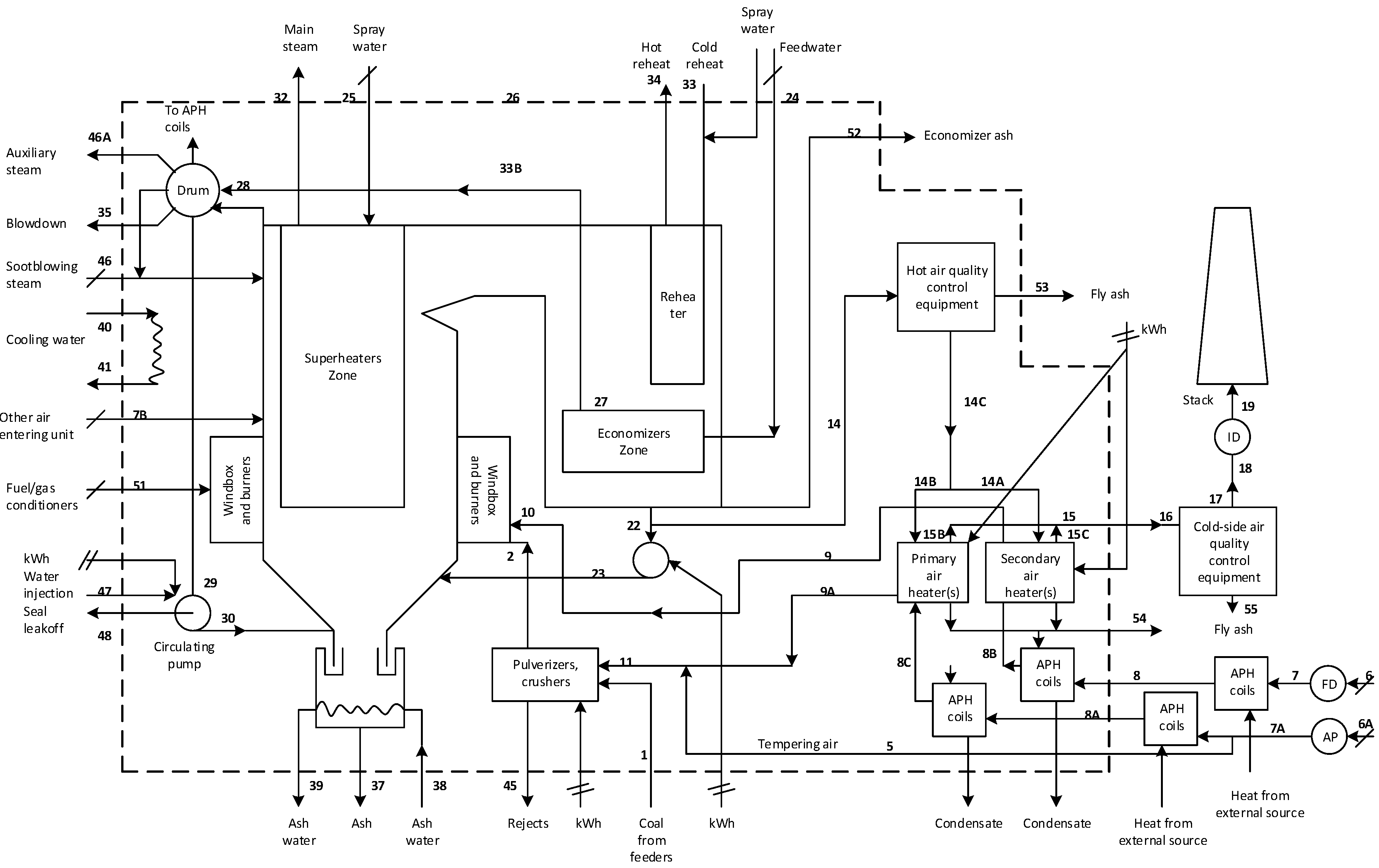
2. Case Study: General Considerations

The unit considered in this study is a 350-MW front-fired, natural circulation, single reheat and balanced draft coal-fired boiler, which forms part of a 1050-MWe conventional power plant located in Spain. Figure 1 depicts the main components and energy flows of the case study boiler. Data from a boiler performance test are used to calculate the state of the boiler, see Table 1. This information is then used in a simulator as variable inputs to calculate all of the thermodynamic properties of the boiler, e.g., energy and exergy flows [12].
For the exergy analysis, the reference temperature is T o = 25 C and the reference pressure is P o = 100 kPa, whereas the chemical composition is that recommended by Szargut [22]. It is noteworthy that thermodynamic simulation of the boiler requires not leaving out the power cycle section; otherwise, data provided by the simulation would not be correct at all. However, in this study, the boiler section is considered only.
Taking into account the complexity of the boiler, an effort is made to simplify it in a collection of components linked to one another and to the environment by means of a set of matter, heat and work flows, also known as physical structure. Therefore, the simplified structure of the boiler is shown in Figure 2. For the sake of simplicity, solid green lines represent air flows; solid light blue and blue lines represent water flows; and finally, solid red lines outline gas flows. Components and flows are identified with a code number, see Table 2. Note that radiation flows can be identified with arrowed-solid lines going to the equipment where radiation is considerable.
It is important to mention that this simplification (or disaggregation level) is defined according to the information available in the plant. It is clear that a high level of disaggregation can be reached, but this requires us to rely more on hypothesis, which may lead to less reliable results and to more computational resources consumption. Therefore, the goal is to find an optimum level of detail that corresponds to the depth of the analysis.

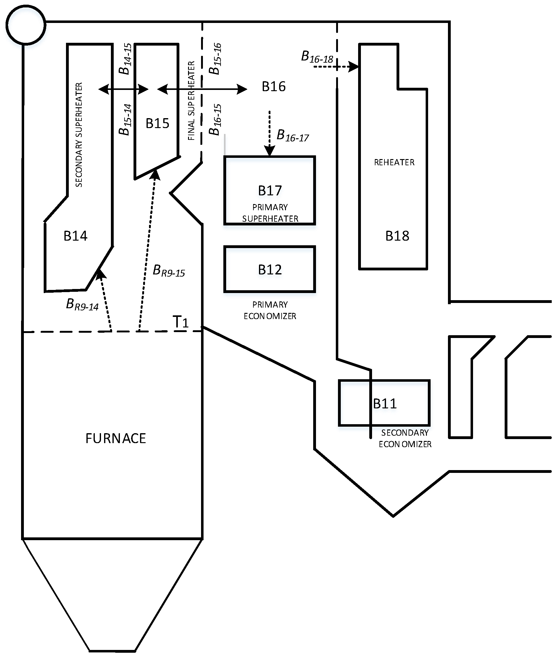
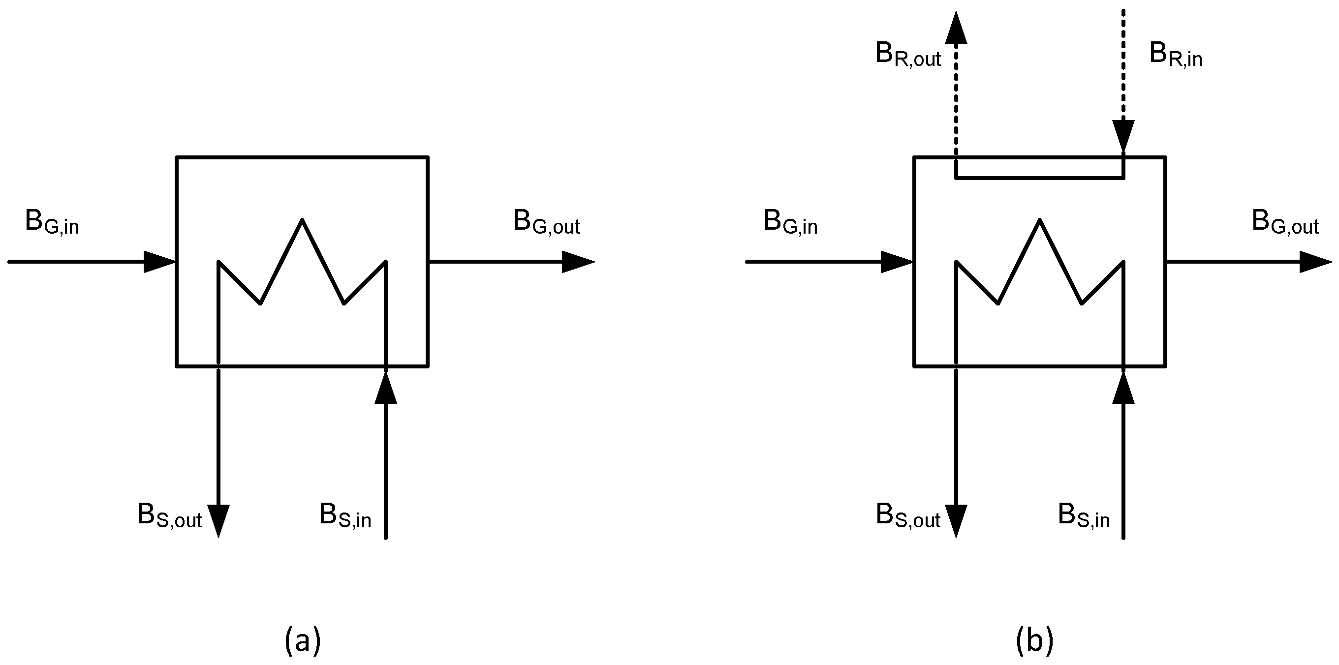
2.1. Radiative Heat Exchangers

In an effort to significantly improve the accuracy of calculations provided by the exergy cost theory, the exergy of radiation is considered in those tube-bundle heat exchangers where the phenomenon of radiation is present.
Taking into account Figure 3, it is possible to categorize three types of tube-bundle heat exchangers according to the heat transfer phenomena present in them: (a) convective tube bundles, which comprise the two economizers in the boiler, B11 and B12; (b) mixed convective-radiative tube bundles, which apply to sections close to the furnace or gas plenum, such as the primary and final superheaters and reheaters, B17, B15 and B18, respectively; and (c) radiative tube bundle, which applies only to the second superheater, B14, since this is located in the furnace enclosure.
For the case-study, directed radiation from the plane at T 1 (top of the furnace) is absorbed by B14 ( B R 9 14 ) and B15 ( B R 9 15 ). To simplify the analysis, T 1 is an average temperature of the top of the furnace. Directed radiation from B14 to B15 and vice versa is also considered ( B 14 15 and B 15 14 ). The plenum considered as a cavity filled with gas is also an emitting source; therefore, it takes radiation to B15 ( B 16 15 ), B17 ( B 16 17 ) and B18 ( B 16 18 ). Finally, B15 also emits radiation to B16 ( B 15 16 ). As regards the simulation, the equations used for the calculation of the exergy flows of radiation are discussed in the following section. Modeling of thermal radiation in large industrial boilers can be consulted in [23,24,25].

Modeling of Exergy Radiation

The term of exergy radiation refers to the maximum work that can be obtained from a flow of thermal radiation in a given environment. Exergy of thermal radiation implies a high degree of idealization and is usually associated with reversible conversion systems. The most accepted models to determine the exergy of thermal radiation are presented by Petela [26], Spanner [27] and Jeter [28].
The models mentioned above differ from each other in the extension of their particular analysis. Surprisingly, reviewing the basic theory, the formulation of Jeter is the one whose efficiency domain coincides closely with the Carnot heat-engine efficiency; besides, it is the most recommended in several references [29,30].
b = 4 3 ρ T 4 1 T 2 T 1
which represents the exergy of thermal radiation per unit surface (kJ/m2). It can be inferred that the exergy of thermal radiation depends on the temperature of the surfaces where radiation is emitted. However, the authors consider that the exergy of thermal radiation depends also on the geometry of the system, so it is proposed to integrate the geometric view factors provided by classical heat transfer. The final expression for the exergy of radiation is as follows,
B = F i j · S · ϵ · 4 3 ρ T i 4 1 T i T 0
where the geometric view factor is:
F i j = R a d i a t i o n e m i t t e d b y A i a n d r e c e i v e d b y A j R a d i a t i o n e m i t t e d b y A i i n a l l d i r e c t i o n s
S is the emitter area surface; ϵ is the emissivity of the surface where the radiative flow has been generated; ρ is the Stefan–Boltzmann constant ( 5.67 × 10 11 kW / m 2 K 4 ) ; and T i corresponds to the average temperature of the surface where radiation is emitted.
Regardless if the significant improvements that this approach may lead to the exergy cost theory, we are aware of its limitations.

3. Thermoeconomics

In this section, the mathematical models needed to determine the exergy costs of the coal-fired boiler under study are explained according to the exergy cost theory [21,31,32].

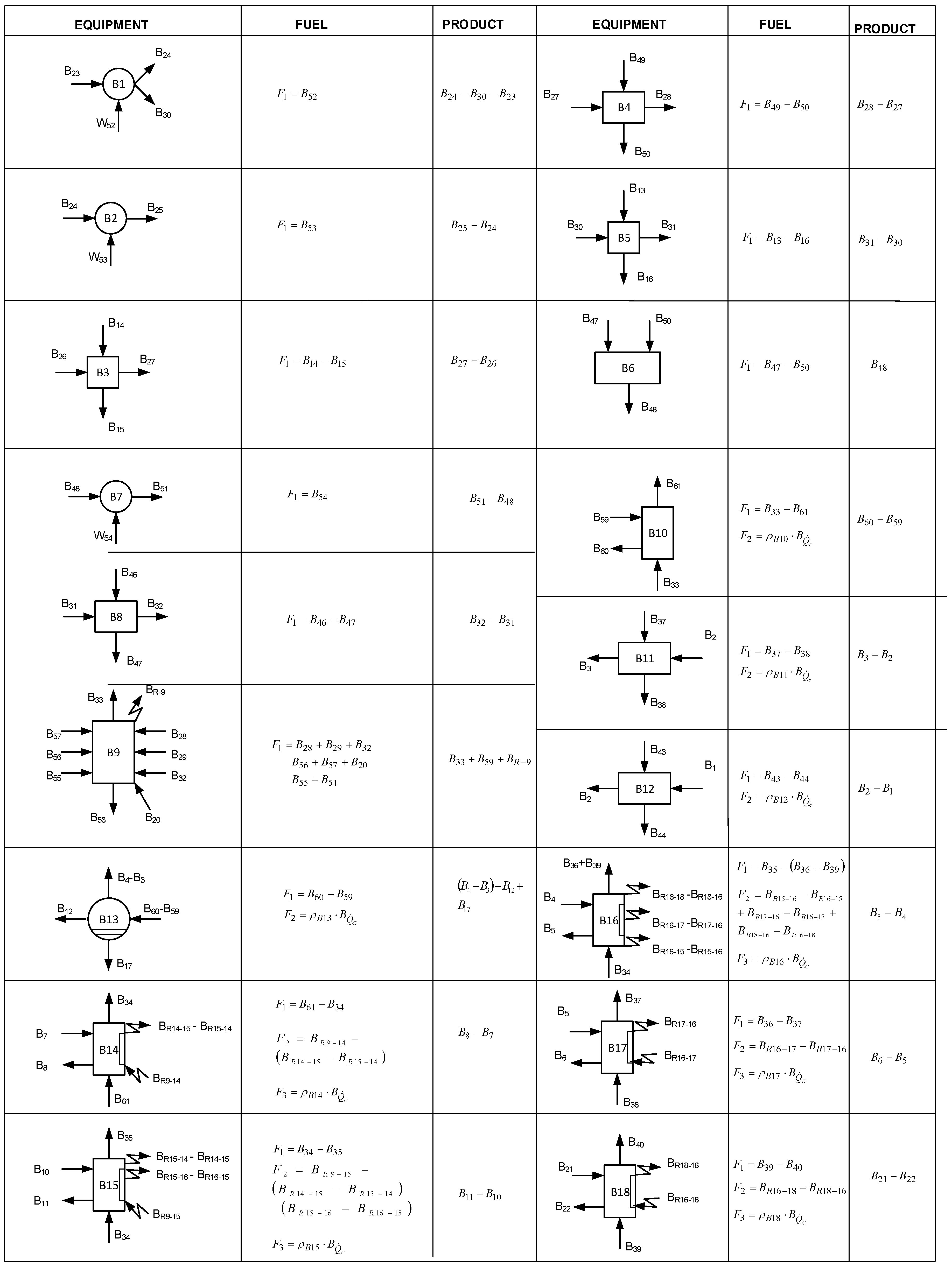
3.1. Fuel-Product Concept

Any system is more than a set of flows (streams) and components (units); it has to do with a series of components having a particular productive function that contribute to the final product. From a practical point of view, it may be said that these systems interact with the environment, consuming some external resources and transforming them into products. In this regard, it is standard practice, in the field of thermoeconomics, to name the flow of resources as fuel (F) and the flow of production as a product (P). Furthermore, it is likely that other flows, whose usefulness is null or simply the use of which in the process is not adequate, leave the process. Such flows are regarded as losses (L). Therefore, the fuel-product definition for productive units holds that,
F P = I 0
where I = T 0 S g in accordance with Gouy–Stodola [33]. Equation (4) is an alternative expression of the exergy balance. Accordingly, the exergy of the product is lower than the exergy of the fuel due to the irreversibilities within the component. Therefore, the efficiency is always lower than one. Therefore, the exergy efficiency is,
ϵ = P F
which can be rewritten in terms of the irreversibilities:
ϵ = 1 I F
from which it follows that efficiency is always lower than unity. In general, it represents a universal ratio for assessing the thermodynamic quality of the processes.
Conversely, the reciprocal of the exergy efficiency is defined as the unit exergy consumption,
k = F P
which may be understood as the fuel exergy required to generate one exergy unit of product. The value of one means that the process can be regarded as reversible, a value greater than one is an irreversible process. As a general rule, the more irreversible the process is, the higher the value of the unit exergy consumption.

3.2. Modeling the Productive Structure

To apply a thermoeconomic analysis, it is necessary to develop a thermoeconomic model that represents how the resources consumed in the plant are distributed among the components [34]. Such a thermoeconomic model is the productive structure and considers the definitions of fuels and products. We depict the productive structure in a diagram constructed of squares, which represent either a productive structure or a dissipative component, and two types of fictitious components: junctions (represented by rhombi) where the products of two or more components are united to form the fuel of another component and branching-points (represented by circles) where an exergy flow is distributed between two or more components. In this regard, a productive component is that which generates an exergy resource that can be used for other components, whereas a dissipative component is the one that purposefully destroys an exergy flow that is no longer useful in the process.
The components are linked to each other by a series of lines representing the exergy-carrying streams referring to either fuels or products. Note that a productive structure depends heavily on the information provided by the power plant. Therefore, different productive structures can be built for a system. Thus, the development of the productive structure is obtained by considering only the information provided by the physical structure explained above.

3.3. The Cost Formation Process

The exergy cost of a product can be defined as the total amount of exergy required to produce an exergy flow [35]. Therefore, the amount of exergy content in the product B is not critical, but its exergy cost B * ; and that is equal to the exergy of the product plus the irreversibility accumulated throughout the process:
B * = B + p r o c e s s I
Therefore, the exergy cost of the fuel needed to produce a unit of exergy of the product is defined as,
k * = B * B
The quest for the irreversibilities that originate the cost of a product leads to a more profound analysis of the process, that is to the process of cost formation. Therefore, a component uses resources to supply its products to another component or to the environment, that is,
F * = P *
where F * is the exergy cost of the resources of the system and P * is the exergy costs of the product. Therefore, it is possible to write the unit exergy costs for the fuel and the product of the system, respectively,
k F * = F * F
k P * = P * P
In a sequential process, the exergy cost of the product is given as:
P i * F T = P i + r = 1 i I r
and:
k P , i * P i * P i = r = 1 i κ r
from which it can be seen that the exergy cost is charged with both the exergy of the product and all of the irreversibilities arising in the components. Equation (14) shows that the unit exergy cost of the product of a component equals the product of the unit exergy consumption of the components taking part in its production.
These equations connect best with the productive structure by conceptualizing the fuel-product representation [31].
P i = B i 0 + j = 1 n κ i j P j
where P i represents the product of the i-th component, B i 0 stands for the final product of the i-th component and κ i j represents the amount of resources provided by the i-th component and necessary to obtain a unit of product from the j-th component, “ P j ”; or in matrix notation,
P = P s + KP P
where KP is defined as a (nxn) matrix containing the unit exergy consumptions of the components, κ i j .

3.4. Exergy Costs of Components

Analysis of the productive structure of a system requires relating the variables of the system (e.g., individual efficiency of the components, recirculations, etc.) to the final product. Such a relationship can be made by means of the fuel-product representation of the exergy cost theory, as seen above. Thus, the thermoeconomic variables can be represented in terms of both the final product and efficiency of each component, as expressed in Equation (16). The total fuel is obtained by:
F T = κ e T P
where κ e T is defined as the vector whose elements are the unit exergy consumptions associated with the environment. Then the product, fuel and irreversibilities of each component can be obtained by means of the following mathematical expressions:
P = | P P s | P = ( U D KP ) 1
F = | F P s | F = K D | P
I = | I P s | I = ( K D U D ) | P
and the unit exergy cost of the product is given as:
k P * = | P T κ e
while the unit exergy cost of the fuel is:
k F * = PF k P *

3.5. Exergy Costs for Radiative Heat Exchangers

In thermoeconomic terms, the allocation of costs in equipment, such as heat exchangers, is simplified when gas and steam (or water) flows are regarded only in the analysis; see Figure 4a. Therefore, the exergy cost balance is given as:
B G , i n * B G , o u t * = B S , o u t * B S , i n * B G , i n * = B G , o u t *
where B G , i n * and B G , o u t * stand for the exergy cost of the gas stream coming in and out of the component, respectively. B S , i n * and B S , o u t * represent the exergy costs of the steam stream flowing in and out of the component, respectively.
Equation (23) meets the rules established by the exergy cost theory. Indeed, this balance holds for equipment located far downstream from the boiler furnace, that is those in which the heat transfer is fundamentally carried out by convection, for example the economizers’ zone.
However, inside a boiler, there are exchangers exposed directly or partly to furnace radiation, which cannot be disregarded [24]. In these cases, the exergy cost balance should be reconsidered in order to allow for the radiative exergy flows. Therefore, in the following, a proposal for the cost allocation of radiative exergy flows is provided.
Taking into account Figure 4b, the exergy cost balance equation takes the form:
B G , i n * B G , o u t * B R , i n * B R , o u t * = B S , o u t * B S , i n *
where B R , i n * and B R , o u t * are the exergy costs of the radiation fluxes coming in and out of the component, respectively.
Additionally, in accordance with the cost allocation rules, it holds,
B G , i n * B G , i n = B G , o u t * B G , o u t
However, we still lack one equation to solve, Equation (24). Therefore, considering the radiative flows as two interdependent streams (or as doublets), which contribute to the heating of the steam, it is possible to write,
B R , i n * B R , i n = B R , o u t * R G , o u t
Finally, the exergy costs of the radiative flows are provided.

4. Thermoeconomic Model

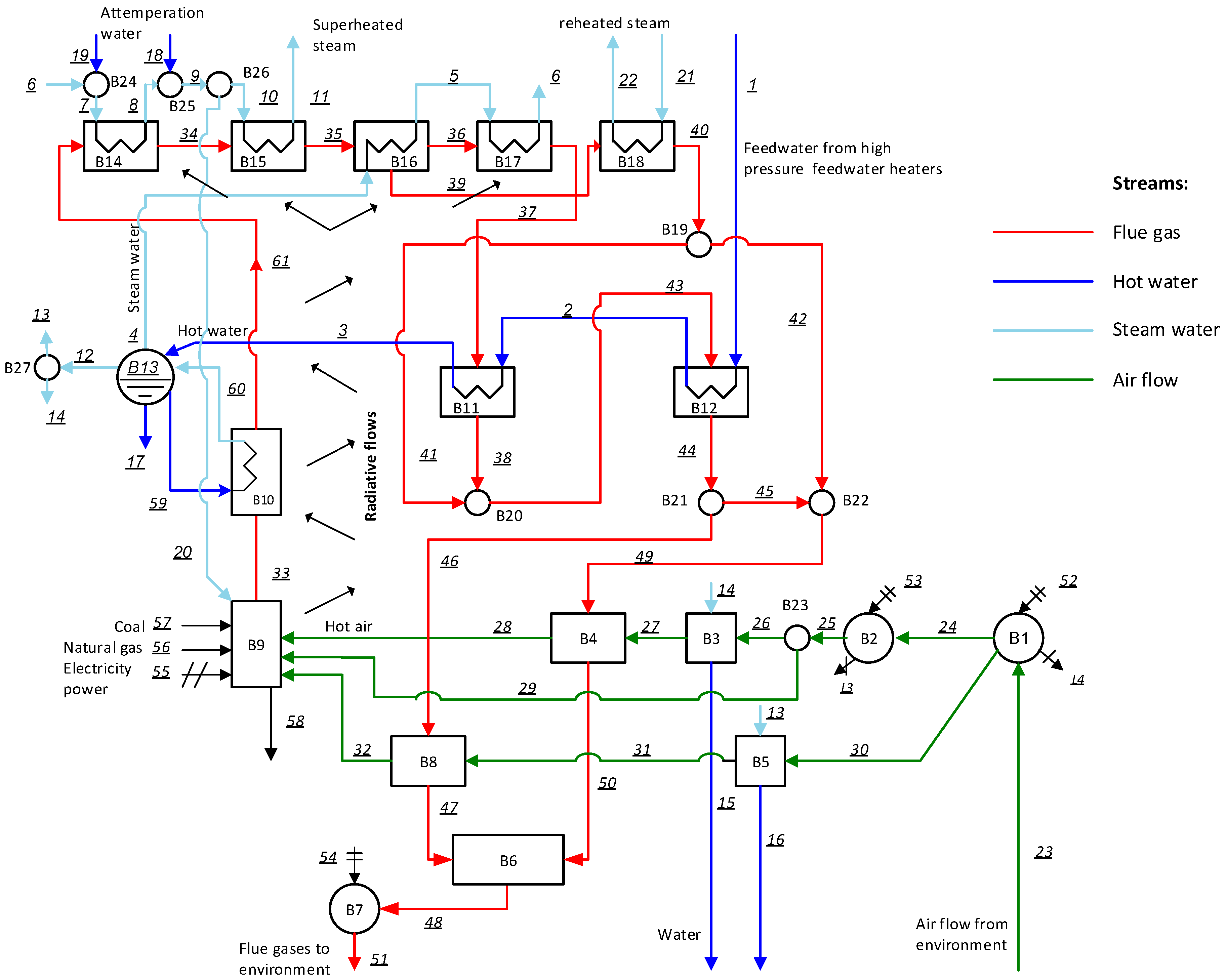
4.1. Fuel-Product Model Definition

The Fuel-Product (F-P) definitions derived in this analysis are based on the exergy cost theory proposed by Valero et al. [21]. It is important to mention that the difference between thermal, mechanical and chemical exergy is not considered, but exergy from radiation is considered as proposed above.

Boiler Section

In reference to Figure 5, the steam coil heaters (B3 and B5) are devices installed to preheat the air streams B 27 B 26 and B 31 B 30 in boilers by means of extracted steam supplied by the steam drum B 14 B 15 and B 13 B 16 , respectively. Likewise, the primary and secondary air-preheaters (B4, B8, respectively) are devices that pre-heat the entering air B 28 B 27 and B 32 B 31 , but unlike the coils, these devices make most of the heat carried by the flue gases B 49 B 50 and B 46 B 47 , respectively. The equipment utilized for taking the air from the environment into the boiler and to increase the pressure of the air B 53 + B 30 B 32 , B 25 B 24 , so as to overcome all of the resistance on its way up to the furnace, are the forced-draft fan (B1) and the primary-air fan (B2), by using a part of the power generated in the power plant B 52 and B 53 , respectively.
The operation of the furnace (B9), on the other hand, transforms the chemical energy of the fuels, coal B 57 and, at times, natural gas B 56 , into thermal energy B 33 . The radiation emitted from the furnace in all directions, B R 9 , is caught by the downstream equipment (e.g., heat exchangers). The air required for the combustion, B 28 + B 29 + B 32 , is supplied by the upstream equipment, namely, forced and primary air fans. It is noteworthy that there appears also a flow of steam B 20 , which refers to the sootblowing steam.
Of further interest are the heat exchangers, which now incorporate a flow of radiation as fuel, as shall be explained below. The function of these devices is to heat the steam in a boiler by means of the heat carried by the flue gases, as well as of the radiation emitted from either the furnace or any other adjacent exchanger. Thus the product of the secondary superheater (B14) is the heating of the steam B 8 B 7 with the heat released by the flue gases B 61 B 34 plus the radiation coming from the furnace B R 9 14 and the one interchanged between this exchanger and the third superheater (B15), B R 14 15 B R 15 14 ; while the product of the third superheater is the heating of the steam B 7 B 8 by means of a fuel composed of two parts: firstly, the heat recovered from the flue gas B 34 B 35 and, secondly, a part of the radiation arriving from the furnace B R 9 15 and the part exchanged with the secondary exchanger (B14) and the plenum (B16) B R 15 14 B R 14 15 + B R 15 16 B R 16 15 . The plenum, on the other hand, uses the heat of the flue gases B 34 B 36 + B 39 past through it and the radiation exchanged between it and the primary (B17), the reheater (B18) and the third (B15) exchangers, as fuel. In Figure 5, it can be readily seen that these flows of radiation are, respectively, B R 16 17 B R 15 17 , B R 16 18 B R 18 16 and B R 16 15 B R 15 16 . It is clear that the product of the plenum is the heated steam B B 5 B B 4 . As to the first superheater (B17), its product is the heating of the steam B 6 B 5 with the heat supplied by the flue gases B 36 B 39 and the radiation exchanged with the plenum B R 16 17 B R 17 16 . Finally, the reheater makes use of a part of the heat released from the flue gas B 39 B 40 on its way down to the economizers and part of the radiation emitted from the plenum B R 16 18 B R 18 16 as fuel, whereas the product is the reheated steam B 21 B 22 running towards the power cycle.
As for the steam drum (B13), the function of this device is to separate water from steam; however, the definition of its fuel and product is complex. Consequently, in this work, it is considered that the product is comprised of two streams: the first is the heating of the water flow B 4 B 3 , and the second is the steam production B 12 . The water flow of the drain is a residue that must be treated downstream in dissipative equipment to quench its harmfulness. The fuel is the product of the evaporator B 60 B 59 . The conversion of water into steam, on the other hand, is carried out in the evaporator (B10). The product is the boiling of the water B 59 B 60 , and the fuel is the heat given off by the flue gases flowing through it B 33 B 61 .
The equipment used to heat the feed water B 2 B 1 and B 3 B 2 is the economizers (B12, B11). The fuel utilized by these pieces of equipment is the heat released by the flue gases on their way out of the boiler B 43 B 44 and B 37 B 38 , respectively. As to the induced-draft fan, its general objective is to pull the flue gases out of the boiler; said differently, it increases the pressure of the gases B 51 B 54 , by using work B 54 , so that they can be subsequently cleaned in an electrostatic precipitator. The electrostatic precipitator has as fuel the entering raw gas B 47 + B 50 , and the product is the cleaned gas B 48 .

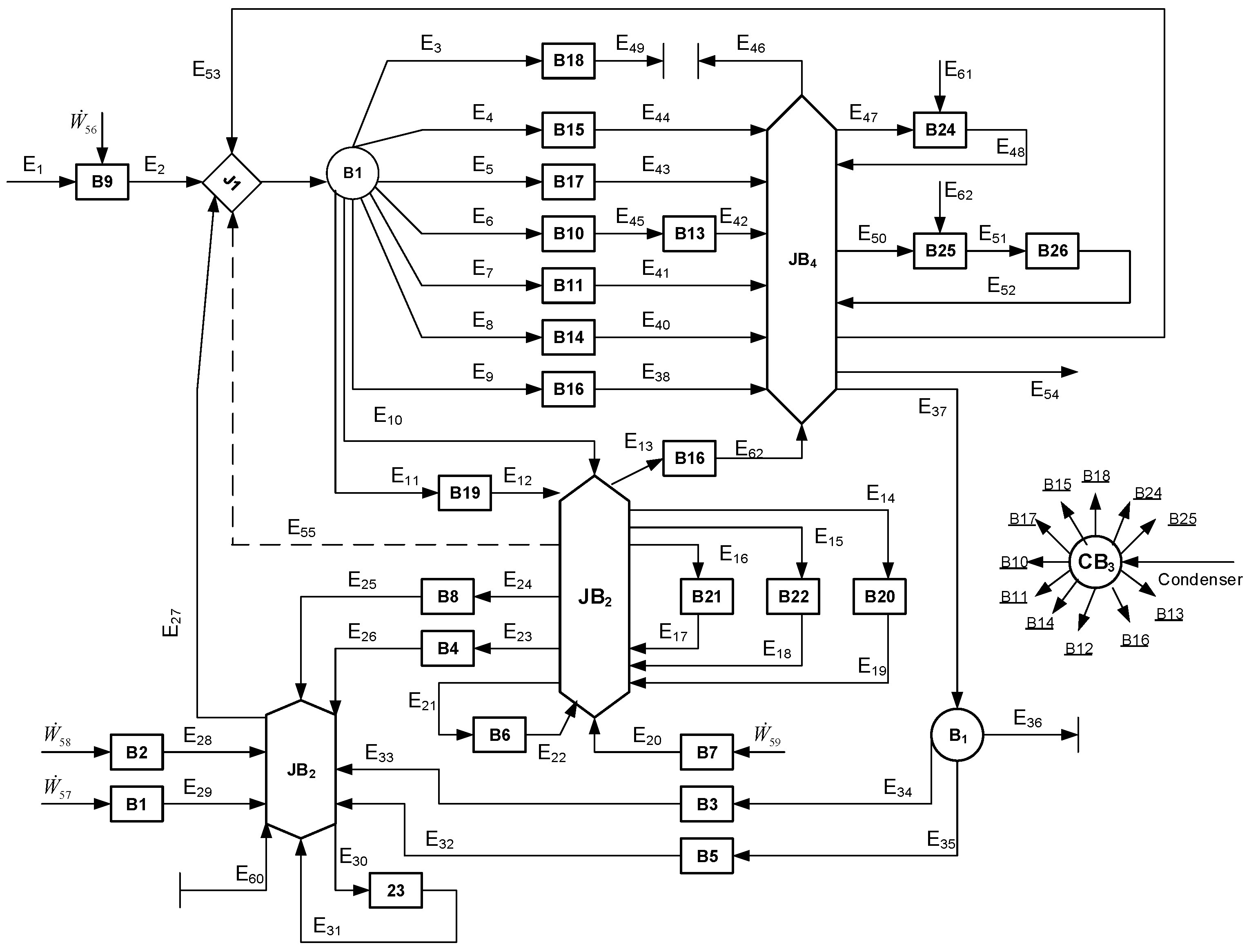
4.2. Construction of the Productive Structure

The productive structure for the boiler (Figure 6) is built by using the F-P models developed above. The definition of the exergy-carrying flows is given in the Appendix. According to the exergy cost theory, both the exergy and exergy cost are conservative for each component located in the productive structure. Note that fictitious components are identified with a particular nomenclature: J (junction point), B (branch point) or JB (junction-branch point).

4.3. Formulation of the Exergy Cost Equations

Table 3 summarizes the equations obtained for the boiler. It is important to comment that all of the exergy costs are conservative.

5. Results of the Exergy Costs

5.1. Exergy Costs for Exergy-Carrying Streams

Table 4 provide the exergy costs of each one of the flows constituting the boiler. For the sake of comparison, we also add a column corresponding to the unit exergy costs without radiation, k n o r a d * .
Note that the unit exergy cost of the superheated steam flow is 2.538 kW/kW, whereas the unit exergy cost of the feeding water is 3.118 kW/kW; the reason is because the feeding water passes through the power cycle before entering the boiler, which indicates that more irreversibilities are added along its path. These values are of considerable significance in the operation of the boiler because if they are compared to the values obtained at different operation states, a deviation will be detected, and a performance improvement is then possible.
Note that it is possible to consider the whole power plant as a unique system; in this case, the unit exergy cost of the fuel (coal) and that of the electricity are 1 kW/kW and 3.160 kW/kW, respectively, which corroborates the fact that exergy costs increases as the final product is reached. It is worth highlighting that these values are similar to those obtained by Lozano et al. [14].
The results of the high values shown by the air stream leaving the induced-draft fan, k 24 * = 6.25 kW/kW, or the primary air fans, k 24 * = 16.036 kW/kW, imply that these types of components are directly powered by electricity, which increases their unit exergy costs by three-fold. In other words, the auxiliary equipment are points where most of the exergy is destroyed, so it is indicative that maintenance and monitoring have to be performed frequently in order to reduce their power consumption.
The unit exergy cost of radiation provided by the analysis, k 24 * = 1.208 kW/kW, can be useful as an index to determine if an efficient combustion in the furnace is at that particular load. An effective air-to-fuel ratio, efficient burners or the quality of the coal can contribute to maintaining the unit exergy cost of radiation in an acceptable range.
For the sake of comparison, it can be seen that unit exergy costs change when radiation is not considered. Of particular interest, the exergy-carrying streams show a lower value in their unit exergy cost when radiation is considered. This reduction comes from the fact that at a higher disaggregation level, the exergy distributes better among the equipment, resulting in a reduction of irreversibilities, thereby assessing more exact and reliable unit exergy costs. The effect of radiation on the unit exergy costs is more significant on the gas side (a reduction of 38%) and on the superheated steam side (a reduction of 31%).
Now, turning to the unit exergy costs of gases, we observe that most of them fall into a range between 1.101 and 1.231 kW/kW; this comes from the fact that they are leaving the furnace (B9) where, as explained previously, the chemical energy of the fuel ( B 57 ) is converted into thermal energy ( B 33 ) and consuming air, but losing an important amount of energy through the walls. More precisely, the furnace is the former component of the process (according to the productive structure); therefore, there is no irreversibility that could be added to the cost formation process. It is important to mention that the unit exergy cost is a key parameter when it comes to determine the causes for the additional consumption of the plant, as evidenced above.

5.2. Exergy Costs for Boiler Components

Using Equations (18) to (22), the thermoeconomics properties of the boiler components are obtained. As expected, the exergy efficiency of the boiler is technically low, 43%, because this efficiency considers intrinsic irreversibilities during the combustion, irreversibilities due to the heat transfer, as well as irreversibilities due to the dissipation of the exergy of the products of combustion (i.e., combustion gases). This value can be compared to the conventional boiler efficiency provided previously by the performance test, 83%. Evidently, conventional efficiency does not take into account all of the types of irreversibilities, but only the energy lost as a product of combustion.
Note that electrically-powered components show higher values in their unit exergy cost of the product; this is due to the fact that most of the exergy in fuel is lost as mechanical irreversibility (i.e., friction) or because the equipment is obsolete and not fitted with energy-efficient motors or variable frequency drivers. In general, the information provided in Table 5 shows us how the resources are being consumed by the components and identifies which can be subject to a general program of energy improvement.

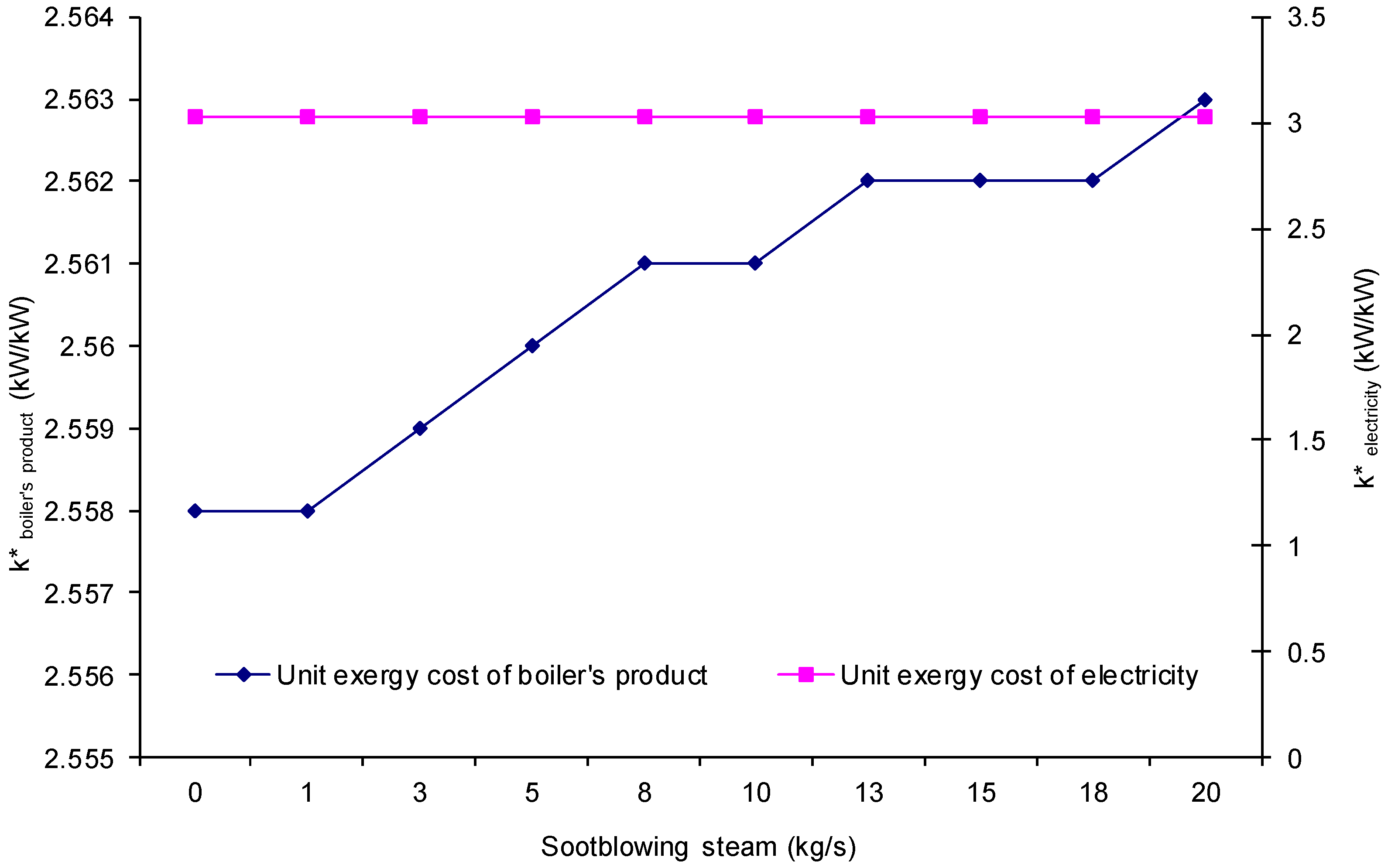
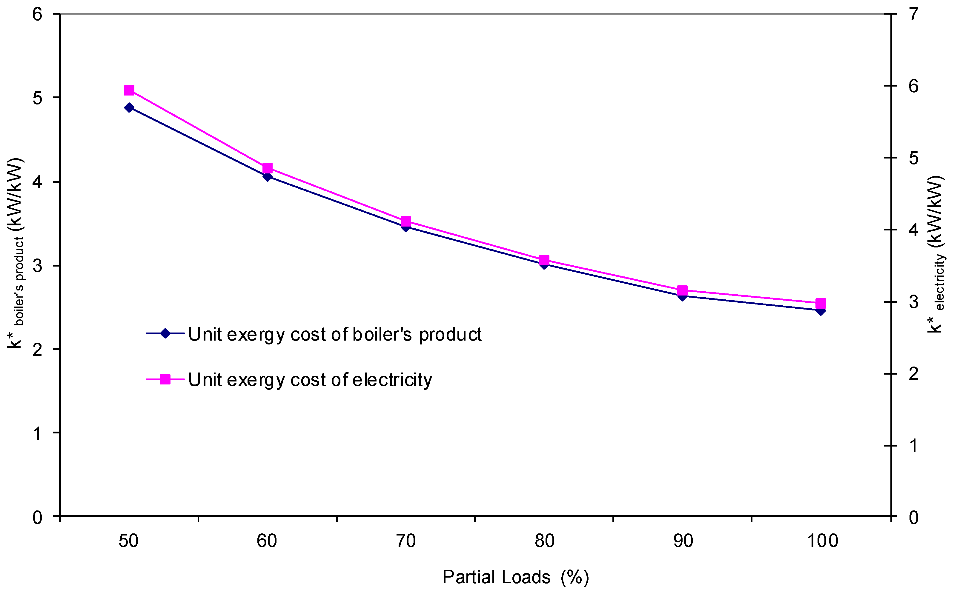
5.3. Effect of Changes in Operating Variables on the Unit Exergy Costs

In this part, we analyze the effect of changes in some operating and ambient variable on the unit exergy costs, in particular the electricity cost, the boiler’s product cost and the radiation cost. From a diagnosis standpoint, this type of analysis is very helpful since it allows one to assess the variation of the unit exergy costs with respect to minor changes in the inlet data. The analysis is performed by setting a reference state (commonly the reference state can be either a design condition, a state of the plant after a major overhaul or the one obtained after an acceptance test). The ranges of operation considered herein are set according to real operating data, which avoid taking ranges of values too conservative, as happens when real data are not available.
From an operational point of view, the boiler can be operated at part loads: from 180 to 350 MWe. However, it can be seen from Figure 7 that operating under its rated capacity has an effect on the unit exergy cost of both the electricity and the product of the boiler. This indicates that operating at partial load is not recommended, since the boiler’s product and the electricity are more expensive in terms of resources and money. Figure 8 shows that changes in the ambient temperature have a significant effect on the unit exergy cost of the boiler’s product (i.e., the superheated steam). In fact, at temperatures below (20 C), the unit exergy cost of the boiler’s product increases rapidly because of the temperature difference between the boiler and the surroundings. As for the electricity, its unit exergy cost does not show any variation, and this is due to the fact that the power output is fixed. As a way of helping to prevent the loss of the availability of the boiler because of erosion in heat transfer tubes, the boiler uses sootblowing steam flows at various superheating zones (in between the final and second superheater; see Figure 1). However, it can be seen from Figure 9 that the use of sootblowing steam increases the unit exergy cost of the superheated steam. This can be explained by considering that the sootblowing steam is extracted from a superheater, which means that its exergy cost is substantially higher than steam extracted from other zones of the boiler. Hence an opportunity area to optimize the use of the sootblowing steam is located. The amount of oxygen in the flue gas indicates how inefficient the combustion in the boiler is. Therefore, with higher percent levels of oxygen in the flue gas, the increase in the unit exergy cost of radiation coming from the furnace is considerable, as evident from Figure 10. Hence, control in the air-to-fuel ratio has to be monitored constantly, since it is key factor in the correct operation of the boiler. Note that the effect of oxygen levels on the unit exergy cost of the boiler’s product is negligible.

6. Conclusions

This paper presents the results of an exergy cost analysis for a real 350-MW pulverized coal-fired boiler. The exergy cost analysis allows one to know the unit exergy costs of flows and components of the boiler. The analysis requires having profound and detailed knowledge of the physical structure of the boiler and its operation in order to facilitate the designing of its productive structure (thermoeconomic model). In particular, the unit exergy cost of superheated steam is 2.538 kW/kW, whereas for the electricity consumed for some of the ancillary components, it is 3.160 kW/kW. This draws attention to the fact that components consuming electrical energy, mainly the ancillary equipment, are those that showed the highest values of unit exergy costs. This is due to the fact that most of these pieces of equipment are obsolete or are not fitted with energy-efficient motors or variable frequency drivers.
The exergetic efficiency of the boiler is 43% for the gross boiler output, whereas its energy efficiency is 83%. The research suggests that low exergetic efficiency is due to the irreversibilities in the combustion process, as well as to the irreversible heat transfer to the surroundings.
Assessment of the radiative thermal exergy permits extending the exergy cost theory to other applications. The unit exergy cost of radiation, 1.208 kW/kW, is of particular importance, as it allows one to determine if an efficient combustion is being performed inside the furnace. For example, a rise in the unit exergy cost implies that the air-to-fuel ratio is not adequate or that the burners are operating incorrectly.
The analysis shows the effect of radiation on the unit exergy costs. Reductions of 38% one the gas side and 31% on the steam side are assessed with a comparison to those obtained without considering radiation exergy flows.
For the operation of the boiler, the results show that operating at partial loads is not recommended, since the unit exergy costs of both boiler’s product and electricity increase considerably. The use of sootblowing steam as a way of preventing erosion in the heat exchangers can be, to a certain limit, adequate as long as this is extracted from zones where exergy costs are low. The effect of oxygen content in the flue gas is also considerable, since a rise in its content means a rise in the cost of the boiler’s product, which means an inefficient combustion.
Overall, a thermoeconomic analysis permits one to know how the resources are consumed through the different components and which flows are the most expensive in terms of exergy, which helps to identify and locate exergy-saving potential areas and, so, perform thermoeconomic diagnosis.

Acknowledgments

The authors wish to thank the Directorate for Research Support and Postgraduate Programs at the University of Guanajuato for their support in the revision of the English language version of this article.

Author Contributions

Victor H. Rangel-Hernandez conceived and designed the thermoeconomic model; Cesar Damian-Ascencio and Juan M. Belman-Flores performed the simulations and sensitivity analysis; Cesar Damian-Ascencio developed the mathematical model; Alejandro Zaleta-Aguilar and Victor H. Rangel-Hernandez analyzed the data and wrote the paper. All authors have read and approved the final manuscript.

Conflicts of Interest

The authors declare no conflict of interest.

Appendix: Definition of the Productive Structure Streams

Table A1. Productive structure exergy flows: boiler.
IDBoiler
E 1 B 57 + B 58
E 2 B 13 + B R 9 B 20 B 28 B 29 B 32
E 3 B 39 B 40 + B R 16 18 B R 18 16 + T o s 22 s 21
E 4 B 34 B 35 + B R 9 15 B R 15 14 B R 14 15 B R 15 16 B R 16 15 + T o s 11 s 10
E 5 B 36 B 37 + B R 16 17 B R 17 16 + T o s 6 s 5
E 6 B 33 B 61 + B R 9 14 + B R 9 15 + T o s 60 s 59
E 7 B 37 B 38 + T o s 3 s 2
E 8 B 61 B 34 + B R 9 14 B R 14 15 B R 15 14
E 9 B 35 B 36 + B 39 B R 16 15 B R 15 16 B R 16 17 B R 17 16 B R 16 18 B R 18 16 + T o s 5 s 4
E 10 B 3 8
E 11 B 4 0
E 12 B 41 + B 42
E 13 B 43 B 44
E 14 B 41 + B 38
E 15 B 42 + B 45
E 16 B 4 4
E 17 B 46 + B 45
E 18 B 4 9
E 19 B 4 3
E 20 B 51 B 48
E 21 B 47 + B 50
E 22 B 4 8
E 23 B 49 B 50
E 24 B 46 B 47
E 25 B 32 B 31
E 26 B 28 B 27
E 27 B 28 + B 29 + B 32
E 28 B 25 B 24
E 29 B 24 + B 30 B 23
E 30 B 2 3
E 31 B 26 + B 29
E 32 B 31 B 30
E 33 B 27 B 26
E 34 B 14 B 15
E 35 B 13 B 16
E 36 B 15 + B 16
E 37 B 1 2
E 38 B 5 B 4
E 39 B 2 B 1
E 40 B 8 B 7
E 41 B 3 B 2
E 42 B 4 B 3 + B 12 + B 17
E 43 B 6 B 5
E 44 B 11 B 10
E 45 B 60 B 59 + T o s 4 + s 12 + s 17 + s 60 s 59 s 3
E 46 B 11 B 1

References

  1. International Energy Statistics. Available online: http://www.eia.gov/cfapps/ipdbproject/IEDIndex3.cfm (accessed on 21 April 2016).
  2. Idehai, O.O.; Waheed, M.A.; Jekayinfa, S.O. Methodology for the physical and chemical exergetic analysis of steam boilers. Energy 2013, 53, 153–164. [Google Scholar]
  3. Stultz, S.C.; Kitto, J.B. (Eds.) Steam: Its Generation and Use, 40th ed.; Babcock & Wilcox: Charlotte, NC, USA, 1992.
  4. Rosen, M.A. Energy and exergy-based comparison of coal-fired and nuclear steam power plants. Exergy Int. J. 2001, 3, 180–192. [Google Scholar] [CrossRef]
  5. Habib, M.A.; Zubair, S.M. 2nd Law-based thermodynamic analysis of regenerative re-heat rankine-cycle power plants. Energy 1992, 17, 295–301. [Google Scholar] [CrossRef]
  6. Sengupta, S.; Datta, A.; Duttagupta, S. Exergy analysis of a coal-based 210 MW thermal power plant. Int. J. Energy Res. 2007, 31, 14–28. [Google Scholar] [CrossRef]
  7. Mohammed, A.; Pouria, A.; Armita, H. Energy, exergy and exergoeconomic analysis of a steam power plant: A case study. Int. J. Energy Res. 2008, 33, 499–512. [Google Scholar]
  8. Goran, D.V.; Mirko, M.S.; Mica, V.V. First and second level of exergy destruction splitting in advanced exergy analysis for an existing boiler. Energy Convers. Manag. 2015, 104, 8–16. [Google Scholar]
  9. Tsatsaronis, G.; Park, M.H. On avoidable and unavoidable exergy destructions and investment costs in thermal systems. Energy Convers. Manag. 2002, 43, 1259–1270. [Google Scholar] [CrossRef]
  10. Regulagadda, P.; Dincer, I.; Naterer, G.F. Exergy analysis of a thermal power plant with measured boiler and turbine losses. Appl. Therm. Eng. 2010, 30, 970–976. [Google Scholar] [CrossRef]
  11. Saidur, R.; Ahamed, J.U.; Masjuki, H.H. Energy, exergy and economic analysis of industrial boilers. Energy Policy 2010, 38, 2188–2197. [Google Scholar] [CrossRef]
  12. Rangel-Hernandez, V.H. Thermoeconomic Diagnosis of Large Industrial Boilers: Microscopic Representation of the Exergy Cost Theory. Ph.D. Thesis, University of Zaragoza, Zaragoza, Spain, 2005. [Google Scholar]
  13. Tsataronis, G. Thermoeconomic analysis and optimization of energy systems. Prog. Energ. Combust. 1993, 19, 227–257. [Google Scholar] [CrossRef]
  14. Valero, A; Lozano, M.A.; Bartolomé, J.L. On-line monitoring of power plant performance, using exergetic cost techniques. Appl. Therm. Eng. 1996, 16, 933–948. [Google Scholar]
  15. Nguyen, C.; Veje, C.T.; Willatzen, M.; Andersen, P. Exergy costing for energy saving in combined heating and cooling applications. Energy Convers. Manag. 2014, 86, 349–355. [Google Scholar] [CrossRef]
  16. Piacentino, A. Application of advanced thermodynamics, thermoeconomics and energy costing to a multiple effect-distillation plant: On-depth analysis of cost formation process. Desalination 2015, 371, 88–103. [Google Scholar] [CrossRef]
  17. Flores-Orrego, D.; Julio, A.M.; Velásquez, H.; de Oliveira, S. Renewable and non-renewable energy costs on CO2 emissions in the production of fuels for brazilian transportation sector. Energy 2015, 88, 18–36. [Google Scholar] [CrossRef]
  18. Acevedo, L.; Uson, S.; Uche, J. Local exergy cost analysis of microwave heating systems. Energy 2015, 80, 437–451. [Google Scholar] [CrossRef]
  19. Valero, A.; Dominguez, A.; Valero, A. Exergy cost allocation of by-products in the mining and metallurgical. Resour. Conserv. Recycl. 2015, 102, 128–142. [Google Scholar] [CrossRef]
  20. Carrasquer, B.; Uche, J.; Martinez-Gracia, A. Exergy costs analysis of groundwater use and water transfers. Energy Convers. Manag. 2016, 110, 419–427. [Google Scholar] [CrossRef]
  21. Lozano, M.A.; Valero, A. Theory of the exergetic cost. Energy 1993, 18, 939–960. [Google Scholar] [CrossRef]
  22. Szargut, J. Exergy Method: Technical and Ecological Applications, 1st ed.; WIT Press: Ashurst, UK, 2005. [Google Scholar]
  23. Diez, L.I.; Cortes, C.; Campo, A. Modeling of pulverized coal boilers: Review and validation of on-line simulation techniques. Appl. Therm. Eng. 2005, 25, 1516–1533. [Google Scholar] [CrossRef]
  24. Diez, P.L. Real-Time Monitoring and Simulation of Pulverized-Coal Utility Boilers. Ph.D. Thesis, University of Zaragoza, Zaragoza, Spain, 2002. [Google Scholar]
  25. Cortes, C.; Valero, A.; Tomas, A.; Abadia, J.; Arnal, N.; Torres, C. A system for slagging control in a coal-fired utility boiler. In Analysis and Design of Energy Systems: Computer-Aided Engineering; ASME: New York City, NY, USA, 2010; pp. 77–84. [Google Scholar]
  26. Petela, R. Exergy of heat radiation. J. Heat Transf. 1964, 86, 187–192. [Google Scholar] [CrossRef]
  27. Petela, R. Exergy of undiluted thermal radiation. Sol. Energy 2003, 74, 469–488. [Google Scholar] [CrossRef]
  28. Jeter, S.J. Maximum conversion efficiency for the utilization of direct solar radiation. Sol. Energy 1981, 26, 231–236. [Google Scholar] [CrossRef]
  29. Badescu, V. Letter to the editor. Sol. Energy 2004, 76, 509–511. [Google Scholar] [CrossRef]
  30. Bejan, A. Advanced Engineering Thermodynamics; John Wiley & Sons: Hoboken, NJ, USA, 1997. [Google Scholar]
  31. Torres, C. Symbolic thermoeconomic analysis of energy systems. In Exergy, Energy System Analysis and Optimization-Volume II: Thermoeconomic Analysis Modeling, Simulation and Optimization in Energy Systems; Eolss Publishers: Oxford, UK, 2009; pp. 61–104. [Google Scholar]
  32. Torres, C.; Valero, A.; Rangel, V.H.; Zaleta, A. On the cost formation process of the residues. Energy 2008, 33, 144–152. [Google Scholar] [CrossRef]
  33. Kotas, T.J. The Exergy Method of Thermal Plant Analysis; Butterworths: London, UK, 1995. [Google Scholar]
  34. Serra, L.; Erlach, B.; Valero, A. Structural theory as standard for thermoeconomics. Energy Convers. Manag. 1999, 40, 1627–1649. [Google Scholar]
  35. Valero, A. The thermodynamic process of cost formation. In Encyclopedia of Life Support Systems; Eolss Publishers: Oxford, UK, 2003. [Google Scholar]
Figure 1. Schematic diagram of the case-study boiler.
Entropy 18 00300 g001
Figure 2. Disaggregation model for the coal-fired boiler under study.
Entropy 18 00300 g002
Figure 3. Directed radiation transfers involved in the exergy modeling of the boiler.
Entropy 18 00300 g003
Figure 4. Exergy cost allocation for radiative equipment. (a) Radiationless model; (b) radiation model.
Entropy 18 00300 g004
Figure 5. Fuel-product (F-P) definition for the main components of the boiler section.
Entropy 18 00300 g005
Figure 6. Productive structure of the boiler according to the F-P model.
Entropy 18 00300 g006
Figure 7. Effect of partial loads’ operation on unit exergy costs.
Entropy 18 00300 g007
Figure 8. Effect of ambient temperature on unit exergy costs.
Entropy 18 00300 g008
Figure 9. Effect of sootblowing steam on unit exergy costs.
Entropy 18 00300 g009
Figure 10. Effect of oxygen content in flue gas on unit exergy costs.
Entropy 18 00300 g010
Table 1. Data from the case-study boiler performance test used as input variables in the simulator.
IDDescription of Boiler SectionValueUnits
1Gross power output332 MW
2Boiler Feeding water flow rate998,880 kg / h
3Make-up water flow rate10,592 kg / h
4Main steam flow rate1,019,620 kg / h
5Main steam pressure15.7 MPa
6Main steam temperature538 C
7Reheat steam flow rate905,378 kg / h
8Inlet reheat steam pressure3.8 MPa
9Inlet reheat steam temperature353 C
10Outlet reheat steam pressure3.5 MPa
11Outlet reheat steam temperature538 C
122nd superheater leaving steam temperature464 C
13Steam drum pressure17.6 MPa
14Dew point7 C
15Atmospheric temperature19 C
16Atmospheric pressure94.7 MPa
17Fuel rate193,456 kg / h
18Forced-draft fan electrical power1235 kW
19Induced-draft fan electrical power2106 kW
20Primary-air fan electrical power981 kW
21Higher heating value of fuel4100 kJ / kg
22Boiler efficiency83.52%
23Natural gas consumption5554 m 3
24Air temperature entering air preheaters32 C
25Flue gas temperature entering air preheaters418 C
26Flue gas temperature leaving air preheaters179 C
27Unit output to cycle768 MW
Table 2. Identification of the boiler components.
IDBoiler Section
B1Forced-draft fan
B2Primary air-fan
B3First steam coil heater
B4Primary air pre-heater
B5Secondary steam coil heater
B6Precipitators
B7Induced draft-fan
B8Secondary air pre-heater
B9Furnace
B10Evaporator
B11Secondary economizer
B12Primary economizer
B13Steam drum
B14Secondary superheater
B15Final superheater
B16Plenum
B17Primary superheater
B18Reheater
Table 3. Exergy cost equations for the boiler section.
ID of the ComponentExergy Cost Equations Equation
B1 B 23 * + B 25 * B 24 * B 30 * =01
B 24 * / B 24 B 30 * / B 30 =02
B 23 * =03
B2 B 53 * + B 24 * B 25 * =04
B3 B 14 * B 15 * B 27 * + B 26 * =05
B 14 * / B 14 B 15 * / B 15 =06
B4 B 49 * B 50 * + B 27 * B 28 * =07
B 50 * / B 50 B 49 * / B 49 =08
B5 B 13 * B 16 * + B 30 * B 31 * =09
B 13 * / B 13 B 16 * / B 16 =010
B6 B 47 * + B 90 * B 48 * =011
B7 B 48 * + B 54 * B 51 * =012
B8 B 46 * B 47 * + B 31 * B 32 * =013
B 46 * / B 46 B 47 * / B 47 =014
B9 B 57 * + B 56 * + B 55 * + B 32 * + B 29 * + B 28 * + B 20 * + B 51 * +
ρ 9 · B N e g * B 33 * B 59 * + B R 9 * =015
B R 9 * / B R 9 B 33 * / B 33 =016
B 59 * / B 59 =017
B10 B 33 * B 61 * + B 59 * B 60 * + ρ 10 · B N e g * =018
B 33 * / B 33 B 61 * / B 61 =019
B11 B 37 * B 38 * + B 2 * B 3 * + ρ 11 · B N e g * =020
B 37 * / B 37 B 38 * / B 38 =021
B12 B 43 * B 44 * + B 1 * B 2 * + ρ 12 · B N e g * = 0 22
B 43 * / B 43 B 44 * / B 44 = 0 23
B13 B 3 * + B 60 * B 4 * B 12 * B 17 * B 59 * =023
B 4 * / B 4 B 17 * / B 17 =024
B 4 * / B 4 B 12 * / B 12 =025
B 4 * / B 4 B 60 * / B 60 =026
B14 B 61 * B 34 * + B R 9 14 * B R 14 15 * + B R 15 14 * + B 7 * B 8 * + ρ 14 · B N e g * =027
B R 9 * / B R 9 B R 9 14 * / B R 9 14 =028
B 34 * / B 34 B 61 * / B 61 =029
B R 9 14 * / B R 9 14 B R 14 15 * / B R 14 15 =030
B15 B 34 * B 35 * + B R 9 15 * + B R 14 15 * B R 15 14 * + B R 16 15 * B R 15 16 *
ρ 15 · B N e g * B 10 * + B 11 * =031
B 34 * / B 34 B 35 * / B 35 =032
B R 9 15 * / B R 9 15 B R 15 14 * / B R 15 14 =033
B R 9 15 * / B R 9 15 B R 15 16 * / B R 15 16 =034
B16 B 35 * B 36 * B 39 * + B R 16 17 * + B R 16 15 * + B R 16 18 * + B 4 * B 5 *
+ ρ 16 · B N e g * =035
B 35 * / B 35 B 36 * / B 36 =036
B 35 * / B 35 B 39 * / B 39 =037
B R 16 17 * / B R 16 17 B R 16 15 * / B R 16 15 =038
B R 16 17 * / B R 16 17 B R 16 18 * / B R 16 18 =039
B17 B 36 * B 37 * + B R 16 17 * + B 5 * B 6 * + ρ 17 · B N e g * =040
B 36 * / B 36 B 37 * / B 37 =041
B18 B 39 * B 40 * + B R 16 18 * + B 21 * B 22 * + ρ 18 · B N e g * =042
B 39 * / B 39 B 40 * / B 40 =043
Table 4. Thermodynamic properties and exergy costs of the flows.
No.Flowṁ (kg/s)P (kg/cm2)T (°C)B (kW)B* (kW)k* (kW/kW) k norad * (kW/kW) Δ k * / k * (%)
1Water289.7018025398,224306,2203.1183.735−19.78
2Water289.70179294128,272356,3062.7783.389−21.99
3Water289.70178321150,973396,4342.6263.240−23.38
4Steam282.90182358313,906798,4832.5443.309−29.56
5Steam282.90175360331,272823,4222.4863.239−30.28
6Steam282.90173424397,879930,8142.3393.062−32.19
7Steam293.70173405398,208934,7522.3473.073−30.93
8Steam293.70169465440,9231,113,0032.5242.998−18.77
9Steam305.60169437440,7081,117,3602.5353.018−19.05
10Steam303.50169437437,7521,109,8642.5353.019−19.09
11Steam303.50161537499,4151,267,7642.5382.848−12.21
12Steam2.04182358226457582.5443.309−29.95
13Steam0.0118235811282.5443.309−29.95
14Steam20.30182358225357302.5543.309−29.95
15Steam20.30121883929982.5543.309−29.95
16Steam0.0112188252.5543.309−29.95
17Steam4.82182358328483552.5543.309−29.95
18Water11.88187170212168463.2284.022−24.59
19Water10.82187170193162353.2284.022−24.59
20Steam2.05169437295774962.5353.019−19.09
21Steam271.0041350351,641892,6402.5382.849−12.25
22Steam271.0038538422,9841,010,0302.3382.746−17.45
23Air378.4011749200.00.00.0
24Air135.5012222413986.2505.29315.31
25Air135.50127281449916.03615.2504.90
26Air113.00127234374916.03615.2404.90
27Air113.00157697848212.17113.950−14.61
28Air113.00139217,61730,0641.7072.241−31.28
29Air22.591274775016.03615.2404.90
30Air242.8012240125046.2505.29315.31
31Air242.8012240125276.3085.36814.90
32Air242.80135632,49451,2221.5762.135−35.47
33Gases434.8012048843,979929,5801.1011.519−37.96
34Gases434.8011253436,208480,4511.1011.519−37.96
35Gases434.8011126376,506414,6931.1011.519−37.96
36Gases249.4011083204,770225,5391.1011.519−37.96
37Gases249.401728118,042130,0151.1011.519−37.96
38Gases249.40157985,95594,6721.1011.519−37.96
39Gases185.4011083152,910167,6261.1011.519−37.96
40Gases185.40153657,42863,2531.1011.519−37.96
41Gases185.40153657,42863,2531.1011.519−37.96
42Gases0.001536000.00.00.0
43Gases434.801561143,333157,9251.1021.520−37.96
44Gases34.801444104,477115,1131.1021.520−37.96
45Gases117.40144428,20831,0791.1021.520−37.96
46Gases317.40144476,26984,0341.1021.520−37.96
47Gases317.40121632,07335,3381.1021.520−37.96
48Gases434.80119840,45244,8351.1081.529−37.96
49Gases117.40144428,20831,0791.1021.520−37.96
50Gases117.401152862094971.1021.520−37.96
51Gases434.80120541,83551,4901.2311.598−29.81
52Elect0.000123539013.1603.1540.18
53Elect0.00098131023.1603.1540.18
54Elect0.000210666543.1603.1540.18
55Elect0.000210666543.1603.1540.18
56Elect0.000252579813.1603.1540.18
57N.G.0.000000.00.00.0
58Coal0.0001,089,0231,089,0231.01.00.0
59Heat0.000106,52300.00.00.0
60Water393.40182358268,051681,8402.5443.309−30.07
61Steam393.40181357437,2991,089,0212.4903.303−32.65
62Gases434.8011375495,193545,4181.1011.519−37.96
R9Rad 280,044338,3131.208
R9-14Rad 97,737118,0731.208
R9-15Rad 76,21392,0711.208
R14-9Rad 2102531.208
R15-9Rad 2102531.208
R16-15Rad 301636431.208
R16-17Rad 172620861.208
R16-18Rad 152418411.208
R14-15Rad 5847051.208
R14-14Rad 7509061.208
R15-16Rad 7308821.208
R17-16Rad 2342821.208
R18-16Rad 2863451.208
Table 5. Thermoeconomic properties of the coal-fired boiler’s components.
No.ComponentF (kW)P (kW)I (kW) k F * k P * η exer (%)
1Induced-draft fan123413211023.16129.47510.73
2Primary-air fan981579243.16154.5065.80
3primary coil heater186046313972.71010.89024.89
4Primary air pre-heater19,58816,92026681.1391.31886.38
5Precipitator40,69240,4522401.1391.14599.41
6Induced-draft fan210513837223.1614.81465.67
7Secondary air pre-heater44,19532,09312,1021.1391.56872.62
8Furnace1,180,0001,140,00036,9001.0011.06892.02
9Evaporator348,786169,247179,5391.1383.10936.61
10Secondary economizer32,08822,70393851.2071.78867.50
11Primary economizer38,85630,04888081.2681.73872.94
12Steam drum588,268587,5037653.1143.18297.88
13Secondary heat exchanger155,92842,714113,2141.1324.21226.86
14Final heat exchanger136,28961,66374,6261.1472.57844.51
15Plenum19,54517,36521801.2241.45584.12
16Primary heat exchanger86,72866,61020,1181.1991.62973.56
17Reheater94,76271,34323,4191.1991.66372.10
18Lower attemperation399,813398,20816052.7132.71999.78
19Higher attemperation443,043440,70823352.7132.72399.65
20Boiler1,126,000472,160653,8401.0132.35243.09

