Article

Control of Self-Organized Criticality through Adaptive Behavior of Nano-Structured Thin Film Coatings

1
McMaster Manufacturing Research Institute (MMRI), McMaster University, 1280 Main Street West, Hamilton, ON L8S 4L7, Canada
2
Department of Engineering, Centro Universitário—Católica de Santa Catarina em Joinville, Joinville 89203-005, Brazil
3
Joint Stock Company “Railway Research Institute”, 3rd Mytischinskaya Street 10, Moscow 129851, Russia
4
Biointerfaces Institute, McMaster University, 1280 Main Street West, Hamilton, ON L8S 4L7, Canada
5
Kobe Steel Ltd., Kobe 651–2271, Japan
*
Author to whom correspondence should be addressed.
Entropy 2016, 18(8), 290; https://doi.org/10.3390/e18080290
Submission received: 21 June 2016 / Revised: 21 July 2016 / Accepted: 2 August 2016 / Published: 9 August 2016
(This article belongs to the Special Issue Entropy Application in Tribology)

Abstract

:
In this paper, we will develop a strategy for controlling the self-organized critical process using the example of extreme tribological conditions caused by intensive build-up edge (BUE) formation that take place during machining of hard-to-cut austentic superduplex stainless steel SDSS UNS32750. From a tribological viewpoint, machining of this material involves intensive seizure and build-up edge formation at the tool/chip interface, which can result in catastrophic tool failure. Built-up edge is considered to be a very damaging process in the system. The periodical breakage of the build-ups may eventually result in tool tip breakage and, thereby, lead to a catastrophe (complete loss of workability) in the system. The dynamic process of build-up edge formation is similar to an avalanche. It is governed by stick-slip phenomenon during friction and associated with the self-organized critical process. Investigation of wear patterns on the frictional surfaces of cutting tools using Scanning Electron Microscope (SEM), combined with chip undersurface characterization and frictional (cutting) force analyses, confirms this hypothesis. The control of self-organized criticality is accomplished through application of a nano-multilayer TiAl60CrSiYN/TiAlCrN thin film Physical Vapor Deposition (PVD) coating containing elevated aluminum content on a cemented carbide tool. The suggested coating enhanced the formation of protective nano-scale tribo-films on the friction surface under operation. Moreover, machining process optimization contributed to further enhancement of this beneficial process, as evidenced by X-ray Photoelectron Spectroscopy (XPS) studies of tribo-films. This resulted in a reduction of the scale of the build ups leading to overall wear performance improvement. A new thermodynamic analysis is proposed concerning entropy production during friction in machining with buildup edge formation. This model is able to predict various phenomena and shows a good agreement with experimental results. In the presented research we demonstrated a novel experimental approach for controlling self-organized criticality using an example of the machining with buildup edge formation, which is similar to avalanches. This was done through enhanced adaptive performance of the surface engineered tribo-system, in the aim of reducing the scale and frequency of the avalanches.

Graphical Abstract

1. Introduction

Machining of hard-to-cut materials with intensive build-up edge formation is a very complex tribological phenomenon. A number of different processes are happening simultaneously within the tribo-system during the cutting process [1,2]. The cutting tool is a critical part of the tribo-system which enables control over the overall machining process. For most widespread cutting tools consisting of cemented carbide with and without ceramic-like thin film Physical Vapor Deposition (PVD) coatings, these processes are:
(1)
material transfer from the chips and workpiece to the tool surface;
(2)
its intensive seizure resulting in buildup (Figure 1);
(3)
frictional heat generation;
(4)
interaction of the adhered fragments of workpiece material with the surface of the tool and;
(5)
the environment;
(6)
phase transformations at the tool/chip/workpiece interfaces.
Metallic chip fragments will interact with different elements coming from the tool and the environment. More importantly, they will react with both oxygen and carbon, formed as a result of phase decomposition (such as WC) at the tool surface, and form a boundary layers of different compounds (such as iron carbides and oxides) [2]. The built-up layer is a structure, which consists of heavily deformed and refined machining material, as well as oxides, carbides and other compounds generated during cutting [2,3,4]. The built-up layer is similar in many ways to a composite material. However, the stability of a built-up layer as a structure under attrition wear conditions is very low. Periodic breakage of the built up layer can cause cracks and damages on the tool surface and eventually yield in a cutting edge break-out (Figure 1).
When machining stainless steels, the essential feature of chip formation is the varying shear strength of the work material at the chip/tool interface: A phenomenon that is similar to stick-slip conditions during friction [5]. It is known that stick-slip phenomenon is associated with self-organized critical processes [6,7] and has a direct relation to metal cutting [8].
To understand this idea in greater detail, we have to consider wear performance of the uncoated cemented carbide cutting tool during machining of one of the most difficult to machine SDSS stainless steel (see Figure 1). Figure 1 demonstrates that machining with buildup edge formation is similar to avalanche-like behavior (see schematic presentation with SEM image of the buildup on the top left corner of the Figure 1). This is confirmed in more detail by progressive SEM studies of the worn surface. It is shown in Figure 1 that during the running-in stage, the buildup forms, accumulates, and eventually breaks off, akin to an avalanche [5,6]. Similar behavior occurs repeatedly during the cutting process. When a large size built up (avalanche) is broken, it can easily tear-off the tool edge and result in a catastrophic failure of the cutting tool (SEM image at the top of Figure 1).
Controlling the self-organized critical processes is of prime importance in tackling these issues. This concept is related to control of a process in which a self-organized system dissipates energy [9,10,11]. The objective of the control is to reduce (a) the probability of occurrence and (b) size of energy dissipation bursts, in other words avalanches (built-ups), of self-organized critical systems [9,10,11]. The dissipation of energy in a self-organized critical system to a lower energy state can be quite damaging when disruption is caused by large avalanches [9,10,11]. When the energy of the system is released through the triggering of smaller scale avalanches, the large avalanches are postponed [9,10,11], or even possibly prevented. One of the most efficient ways to realize such strategy in the tool/chip/workpiece system is through adaptive response of surface engineered tooling. The goal of this paper is to demonstrate how control of self-organized critical performance could be made through the application of PVD thin film coatings combined with optimization of machining conditions to achieve better adaptive response of the surface engineered nano-material. A combination of thermodynamic modeling and detailed investigation of the coated cutting tool’s wear performance was performed to achieve this goal.

2. Thermodynamic Analysis

A general feature typical of the process of cutting of hard to machine materials, such as Ti alloys, Ni-based super alloys and, in particular, the latest generation of super duplex stainless steels, is a very intensive adhesive interaction on the tool/chip interface leading to seizure and formation of built-up edge [2]. This could be characterized as a catastrophic frictional condition [2].
We have to stress that the tool/chip/workpiece tribo-system is a system where different parts (in our case tool, chip, workpiece) are interconnected or “functionally integrated”, so the failure of one part may cause the rest of the structure to fail [6]. To control such complex engineering systems, an integrative approach is of critical need.
To understand a number of very complex and interconnected mechanisms that are taking place within the tool-buildup-workpiece tribo-system during cutting, a thermodynamic analysis of the frictional processes needs to be carried out. In our previous studies, thermodynamic analysis was conducted for one frictional body (cutting tool) [2,12]. In this research, we are analyzing a more complex system consisting of three frictional bodies: cutting tool/buildup/chips (work piece).
A seizure during friction is initiated by two major processes [13]: formation of juvenile surfaces and plastic deformation, in other words, some activation of the surface is critically needed. A seizure leads to a decrease in the free energy of the system, since it decreases the surface energy by reducing the surface area. Hence, this is a spontaneous process with positive entropy production. On the other hand, to initiate a seizure it is necessary to create juvenile surfaces and this is a non-spontaneous process with the increase in surface energy, which is accompanied by a negative entropy production. Furthermore, during the plastic deformation process, localization of deformation and the consequent non-uniform distribution results in entropy decrease in the frictional body.
In this regard, let us try to analyze the entire process of the tool/chip interaction as follows.
The chips of austenitic steel tend to adhere to the surface of the uncoated coating tool. However, the surface layers of the uncoated tool have insufficient adaptability. Therefore, the energy released during cutting may not be enough to initiate self-organization on the tool surface. In this case, the system tends to initiate seizure and stop the friction (this leads to a decrease in entropy production, as there is no friction within the zone of seizure).
For the coated tool, the process looks different. The coating has the ability to adapt to external stimuli, i.e., to self-organize. A part of the cutting energy is spent on self-organization of the coating layer (by forming a nano-layer of thermal barrier/lubricating tribofilms [2,14,15]). Thus, the tribo-system is able to reduce the entropy production by means of self-organization, instead of energy dissipation through surface damage. Thus, the intensity of seizure is much less in the coated tool.
A similar thing happens during the initial acceleration in cutting speed. However, a greater speed leads to a more intense release of energy, and respectively, a greater and more complete self-organization on the coated tool surface. In theory, this fully corresponds to the strategy of running-in on the edge of seizure during external friction [16,17,18].
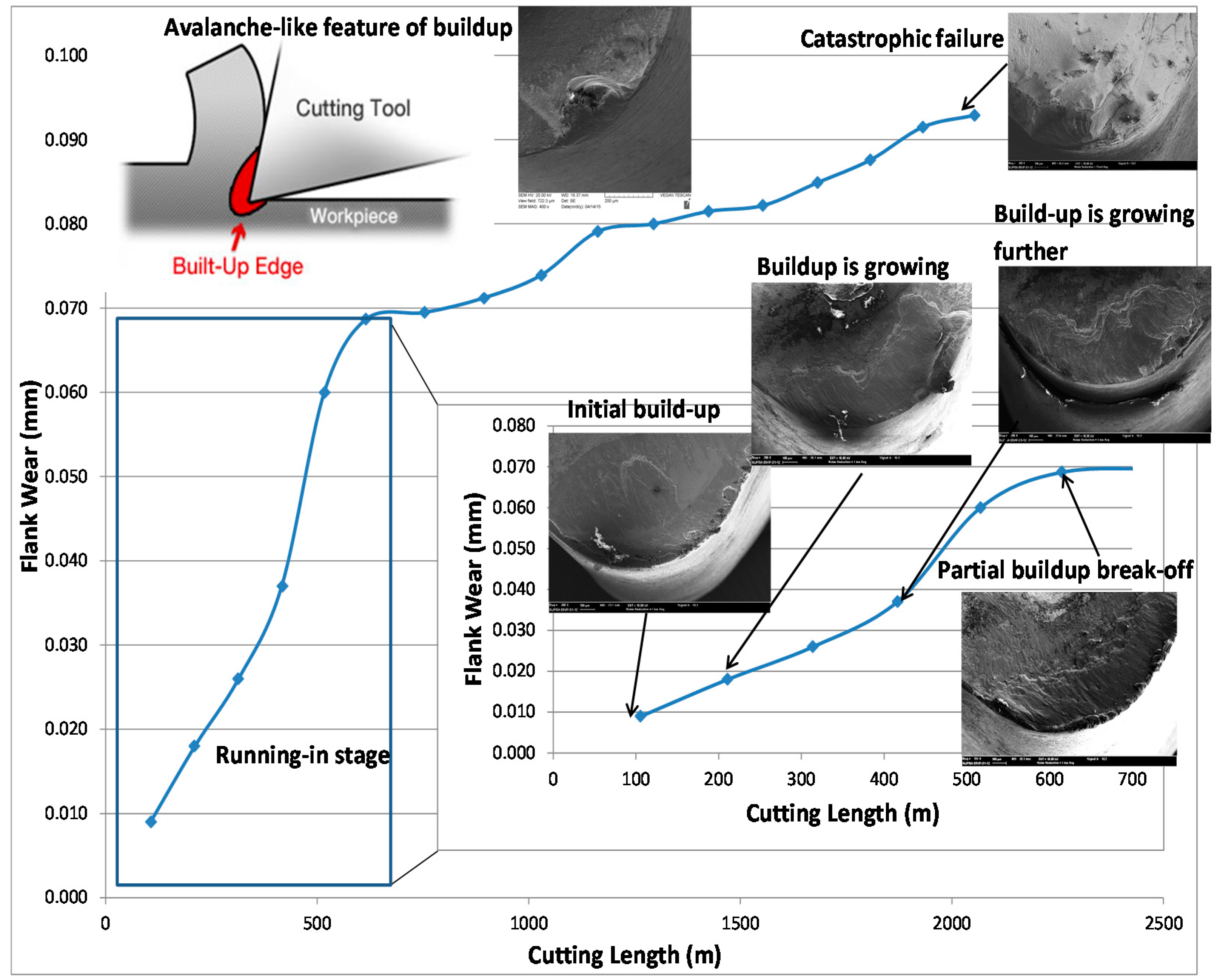
The flow of the material in front of the tool face and the structure of build-ups both resemble the formation of vortices within an impeded flow (Figure 1). The corresponding torque generated by these vortices can tear off the built-ups from the tool. The torque associated with large vortices (built-ups) can even tear off some portions of the tool tip especially under intensive adhesion conditions. This situation was resembled to occurrence of a large avalanche previously. As discussed before, the goal of this study is to replace one big avalanche with several smaller avalanches through an application of adaptive coatings [9,10,11]. Reducing adhesion and seizure, controlling the flow speed and consequently facilitating the material flow, through application of self protective/lubricating tribo-films in the contact zone, we replace large destructive vortices with smaller vortices.
An integrative analysis of the tribo-system, requires consideration of both contacting bodies (the tool and the workpiece material), as well as formed chips and the environment. Therefore, in this model, it is considered that the worn material remains within the system and does not leave the system with its entropy. In this way, the wear can be regarded as the formation of new surfaces.
Let us consider the balance of entropy change in the system:
The entropy change during tool wear (formation of new surfaces) dSw characterizes the tool wear. Due to the additivity of entropy, the greater the absolute value of dSw, the greater the wear of the tool.
The change in entropy during chip formation (and formation of new surfaces) dSch characterizes the intensity of the chip formation. Due to additivity of entropy the more absolute value dSch, the easier the chip formation process, which corresponds to higher chip velocity as well as shear angle and at the same time, smaller chip thickness (higher chip compression ratio, see below in Results).
The part of entropy production dSi1 is inherent in the tool without regard to physical and chemical transformations.
The part of entropy production dSi2 entropy is inherent in the workpiece material without regard to physical and chemical transformations. The part of entropy production dSi11 is associated with the tool, which takes into account the physical-chemical transformations on the surface. The part of entropy production dSi21 is associated with the workpiece material and takes into account the physical and chemical transformations on the surface. The part of the entropy production dSs is associated with build-up formation. The part of entropy production dSa is associated with build-up tearing off.
The entropy flow is associated with the exchange of energy with the environment dSe. The change in entropy of such tribo-system similar to Reference [2] will be as follows:
dS = dSe + (dSi1 + dSi2) − │dSw + dSch│ + (dSi11 + dSi21) + dSs − │dSa
The terms in Equation (1) are combined by an identical type of process. The first term (dSe) is the entropy flux. We will consider it as an independent variable and unchanged, i.e., its intensity is independent of the state of the system and is determined only by the intensity of the friction process (in our case is chiefly related to the increase in cutting speed). The latter two terms united in brackets, (dSi1 + dSi2), represent the entropy production and are positive because they are related to the propagation of heat by frictional bodies. The third pair of terms are combined in absolute terms and have a “minus” sign, because during the formation of new surfaces, the surface energy increases. The fourth pair of terms (dSi11 + dSi21) describe the physical and chemical processes on the surfaces. This sum, as are the single terms, could be either positive or negative. For example, the surface oxidation of the steel chips is a spontaneous process with positive entropy production. The formation of protective surface tribo-films on the surface of the cutting tool is a non-spontaneous process, especially after self-organization, as shown in Reference [2]. The fifth term (dSs) is visibly positive because seizure reduces the surface energy. The sixth term (dSa) is visibly negative, as the build-up tears off, new surfaces form, and, respectively, the surface energy increases. In differentiating Equation (1) with respect to time, and considering the stationary process we get:
d S e d t + ( d S i 1 d t +   d S i 2 d t )   | d S w d t + d S c h d t | + ( d S i 11 d t +   d S i 21 d t ) +   d S s d t   | d S a d t | = 0
or:
| d S w d t + d S c h d t | =   d S e d t + ( d S i 1 d t +   d S i 2 d t )   + ( d S i 11 d t +   d S i 21 d t ) +   d S s d t   | d S a d t |
The amount of the left part of Equation (3) represents the entropy rate change due to tool wear and chip formation. It should be noted that both of the terms in the left part of Equation (3) have the same sign (negative), therefore:
| d S w d t + d S c h d t | = | d S w d t | + | d S c h d t |
The change in this sum could yield simultaneous change in either term or could result in different changes in each term. For example, reduction of this sum could lead to a simultaneous reduction in the both tool wear rate and the intensity of the chip formation (decrease in both terms); reduction in the tool wear rate (a decrease in the first term) and increase in the chip formation rate (increase in the second term); increase in tool wear rate (increase in the first term) and reduction of chip formation rate (reduction of the second term).
Substituting Equation (4) into Equation (3) we obtain:
| d S w d t | =   d S e d t + ( d S i 1 d t +   d S i 2 d t )   + ( d S i 11 d t +   d S i 21 d t ) +   d S s d t   | d S a d t | | d S c h d t |
It follows from Equation (5) that the more intensive the chip formation, the lower the intensity of the tool wear, and vice versa.
With the decrease of tool wear, due to lower friction, chip formation becomes easier. By ease of chip formation, we mean a higher shear angle and consequently thinner chips with higher chip velocities.
From Equations (3) and (4), it follows that with increasing d S e d t and ( d S i 1 d t +   d S i 2 d t ) the wear rate of the cutting tool and/or the intensity of the chip formation will increase. Considering that d S e d t is highly affected by cutting speed, this is quite natural because the sum of these terms describes the intensity of the cutting process in general.
From Equations (3) and (4), it follows that with increasing d S s d t the rate of tool wear and/or intensity of the chip formation will increase. This is due to the fact that, during adhesion, additional energy is released that is associated with the decrease in the surface energy. It is well known that very high seizure and a consequent high built up edge will result in high tool wear. Higher seizure also adversely affects chip formation and reduces its intensity. From Equations (3) and (4), it follows that with the increase of | d S a d t | the tool wear rate and/or the rate of the chip formation will decrease, because the formation of new surface requires energy to form these surfaces. In the following section, it will be shown how, through controlling this term, significant enhancements can be obtained in terms of tool life and chip formation.
The influence of fourth terms (dSi11/dt and dSi21/dt) on the wear rate of the tool and/or the intensity of the chip formation depend on the signs in front of the terms in parentheses. During regular oxidation of the processed material, energy is released, therefore, it is a spontaneous process and d S i 21 d t is positive. For example, if the cutting tool material were to also undergo regular thermal oxidation, without self-organization, then the energy would be released, i.e., it would be a spontaneous process and d S i 11 d t would be positive. Usually, spontaneous processes on surfaces prevail with a relatively small d S e d t , i.e., during cutting at low intensity when the power of cutting is not enough to initiate self-organization. Spontaneous processes at surfaces may prevail when there is no opportunity for self-organization to be initiated, such as a lack of complexity of the cutting material [19], which is possible for an uncoated tool.
Once the self-organization on the surface of the cutting tool is initiated, the value of d S i 11 d t term can be negative or positive, but it is much less than it would be without self-organization. Let us consider the last two terms on the right side of Equation (3). During the formation of a built-up edge, the chips adhere to the cutting tool surface. The formation of build-up takes place due to the progressive, multilayer adherence of the chips to the tool surface, i.e., the first scales of the chips adhere to the tool surface and subsequent scales adhere to the previous scales. Let us suppose the buildup consists of n layers of the scales. In this case:
d S s d t = 2 B τ T d n d t
where B is the average size of a scale and τ is surface energy of scales. At a certain period of a cycle that includes the build-up formation and build-up tearing off, with an increase in the thickness of the build-up (increasing of n), the d S s d t increases as well. After reaching a certain thickness of build-up, the formed build-up will be fractured and torn away, i.e.,
d S a d t = 2 B τ m   d n d t
where τm is surface energy of the material where the tearing has occurred. It is difficult to compare the values of d S s d t and | d S a d t | due to the different time of formation and separation of the build-up. Let us try to compare the integrated value (integrated over time):
Δ S s =   2 B τ n T
Δ S a = 2 B τ m n T
It should be noted that during the formation of build-up:
n ≫ 1
Separation typically occurs on the material with a lower surface energy, therefore, typically:
τ   >   τ m
Using Equations (10) and (11):
Δ S s >   | Δ S a |
The greater the difference, Equation (11), the higher the tool wear rate can be. If, by analogy with avalanches (self-organized critical process [6]), we replace thick built-ups (n layers) with thinner ones (m layers where 1 ≤ mn), then Equations (8) and (9) will become:
Δ S s m = 2 B τ m T
Δ S a m = 2 B τ m m T
Taking into account Equations (13) and (14), ceteris paribus:
Δ S s | Δ S a | > Δ S s m | Δ S a m |
Taking into account that the period duration of adhesion and separation will be close for thin (probably mono-layered or consisting of a few layers) build-ups, it can be assumed that:
d S s d t   | d S a d t | >   d S s m d t   | d S a m d t |
Accordingly, by replacing these terms in Equation (3), the sum of the right side of Equation (3) will be reduced and, therefore, wear rate will likely be lower as well. Thus, through non-spontaneous processes inside tribo-system (self-organization), as well as the formation of thinner layered build-ups, rather than a thick build-up, the value | d S w d t + d S c h d t | decreases. Thus, it can be demonstrated that, by replacing a thick built-up with several smaller ones, the intensity of tool wear will be reduced, whereas the chip formation will be improved. Improvement of chip formation is accompanied by less cutting forces and power consumption. The tribo-films, which are also known in the literature as secondary (i.e., formed during friction) structures [18], are formed on the surface to protect the tooling material from direct interaction with the counter-body (in our case chips and workpiece). The physical and chemical processes of secondary structure formation can be non-spontaneous, and be accompanied by a negative entropy production [2]. In this case, it leads to reduced wear rate and entropy production.
If tribo-materials in contact cannot initiate self-organization and the formation of secondary structures required by friction, (for instance if the tribo-materials do not possess sufficient complexity [19]) then the system tries to reduce the wear rate by terminating the friction process through seizure. Presumably this occurs on the surface of the uncoated tool (see Experimental Section below). The nano-multilayer coating on the surface of cutting tool has a fairly complex structure and a non-equilibrium state [15,19,20,21]. This increases the probability of self-organization initiating along with spontaneous processes of secondary structure formation. Most of the friction energy has been spent on non-spontaneous processes on the coating surface, so less energy is available for adhesive interaction with the workpiece material. With an increase in the initial cutting speed, the intensified non-spontaneous processes are initiated [22], respectively, and even less energy remains on the surface to cause damage to processes. This strategy is somewhat similar to the earlier-developed approach for external friction conditions [16,17].

3. Experimental Section

Two nano-multilayered Ti0.2Al0.55Cr0.2Si0.03Y0.02N/Ti0.25Al0.65Cr0.1N and Ti0.15Al0.6Cr0.2Si0.03Y0.02N/Ti0.25Al0.65Cr0.1N coatings were deposited using Ti0.2Al0.55Cr0.2Si0.03Y0.02, Ti0.15Al0.6Cr0.2Si0.03Y0.02N, and Ti0.25Al0.65Cr0.1 targets fabricated by powder metallurgical process. The cemented carbide K 313 Kennametal inserts (CNGG432FS) were used for cutting tool life studies. Coatings were deposited in an R&D-type hybrid PVD coater (Kobe Steel Ltd., Kobe, Japan) using a plasma-enhanced arc source. Samples were heated up to about 500 °C and cleaned through an Ar ion etching process. Ar-N2 mixture gas was fed to the chamber at a pressure of 2.7 Pa with a N2 partial pressure of 1.3 Pa. The arc source was operated at 100 A for a 100 mm diameter × 16 mm thick target. Other deposition parameters were: Bias voltage 100 V and substrate rotation of 5 rpm. The thickness of the coatings studied was around 3 micrometres for film characterization and cutting test work. The characteristics of the TiAlCrSiYN/TiAlCrN coatings are presented in Table 1 [20].
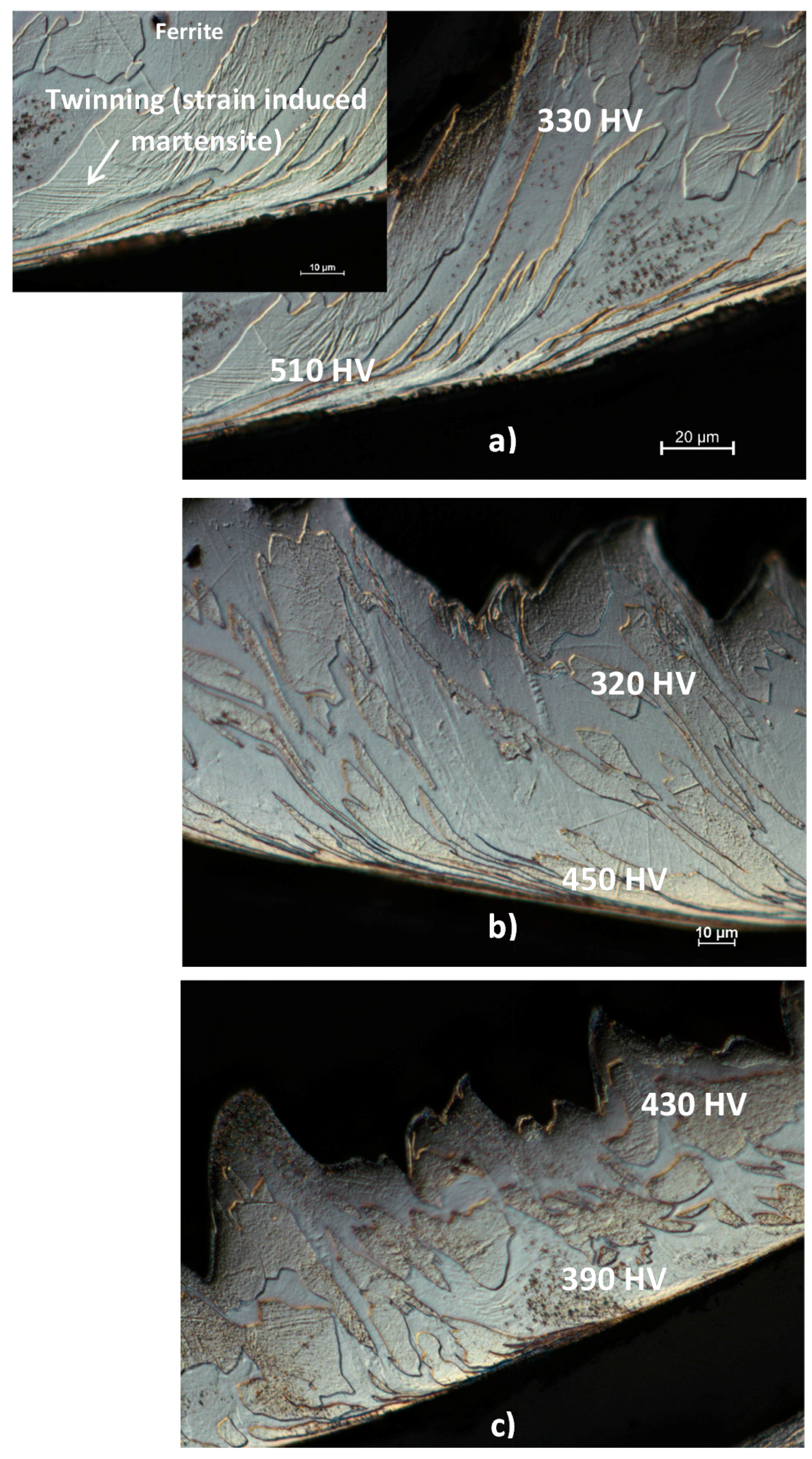
To reveal the microstructure of the SDSSUNS32750 workpiece, samples of this material were metallographic prepared by polishing and etching in Aqua regia 1:3 HNO3:HCl solution. The microstructure of SDSS workpiece and microstructure of chip cross section generated during cutting process, as well as the worn tool surface, were characterized using both an Optical (Olympus BX60 equipped with UC30 camera, Center Valley, PA, USA) and Scanning Electron Microscopy (SEM) facilities (Vega 3-TESCAN, Brno, Czech Republic).
Two sets of turning tests were performed: Semi-roughing tests to accelerate build up formation and perform progressive SEM studies (
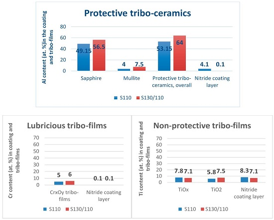
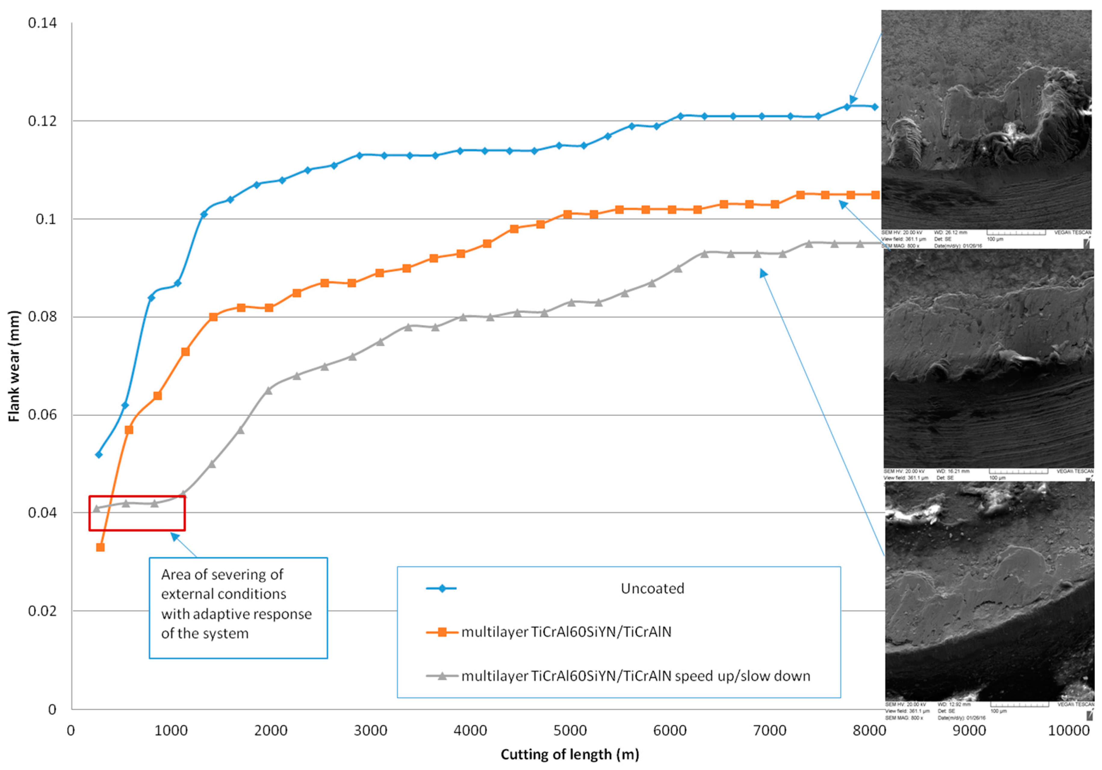
Figure 1). For the semi-roughing operation, cutting conditions were the following: Speed, m/min-60; feed rate, 3.3 mm/rev; depth of cut, 1 mm. For finishing, machining conditions that are widely used in practice were used (
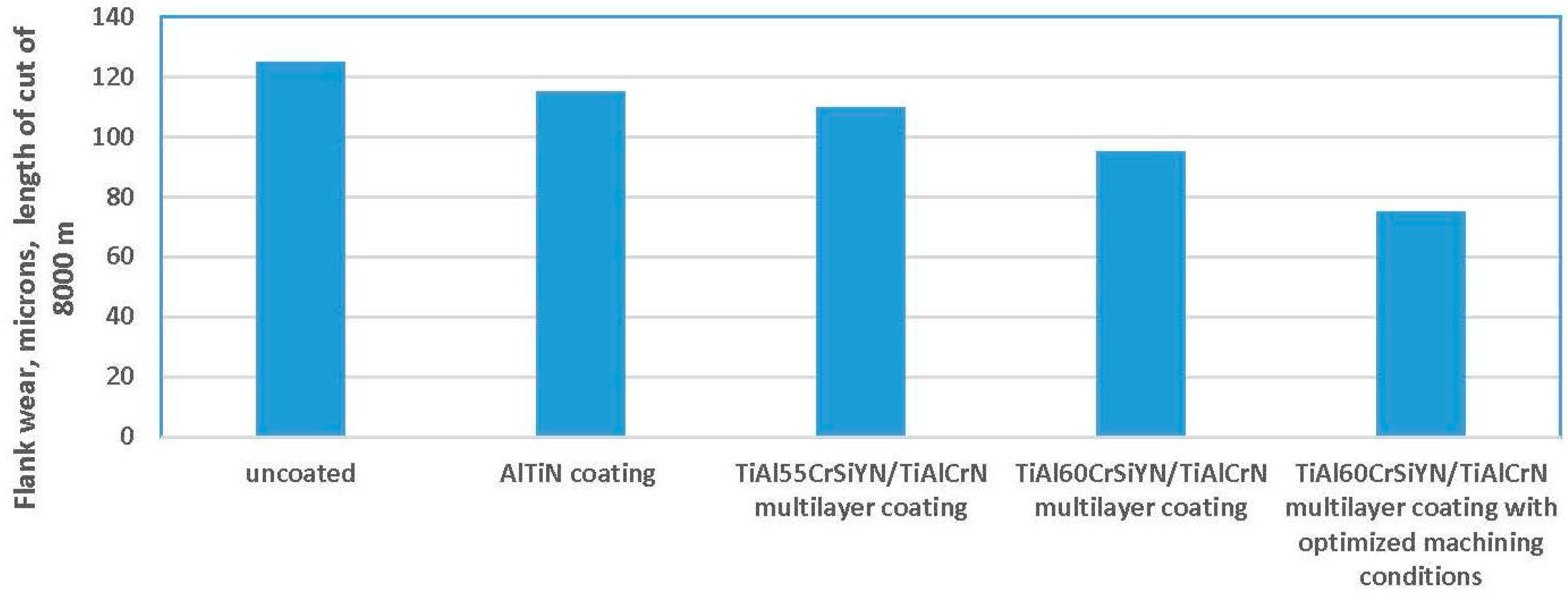
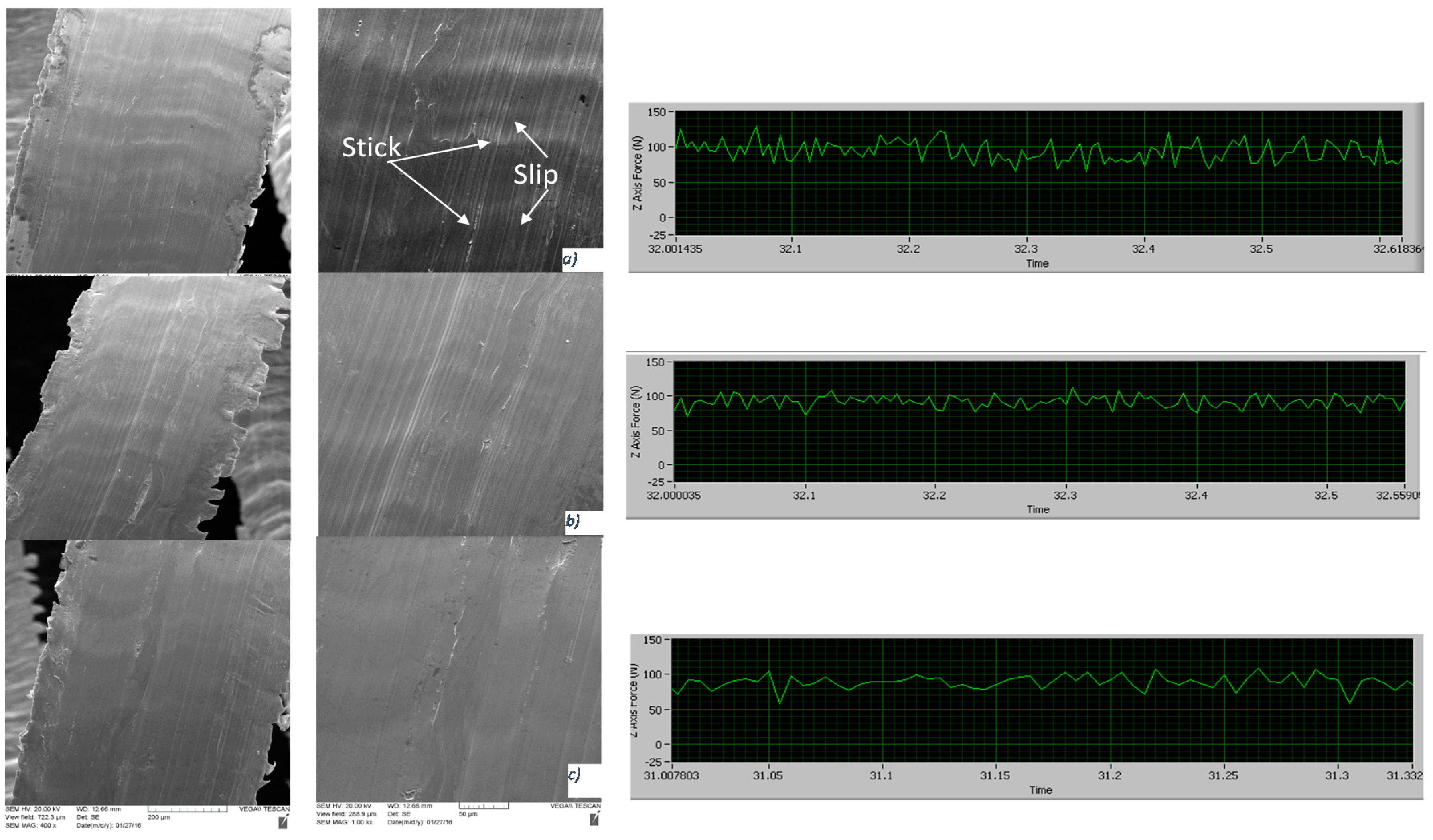
Figure 2). The experiments were performed at speeds of 110 m/min, 130 m/min and on accelerated test conditions (130 m/min at the beginning of machining followed by slowing down to 110 m/min for the remainder of the tool’s life), which were designated as S110, S130 and S130/110 respectively. A cutting speed of 110 m/min can be characterized as usual in industrial practice. Other machining parameters were the following: Feed rate of 0.125 mm/rev and depth of cut of 0.25 mm under wet cutting condition. The tool life criterion was set to flank wear of 0.1 mm. Tool wear rate was characterized by its cutting length. The machining experiments were performed in a Boehringer VDF 180CM turning machining center (FFG Werke GmbH, Uhingen, Germany). The force measurements were performed with a Kistler dynamometer (type 9121, Kistler Instrument Corp., Amherst, NY, USA). The sampling rate was 200 data points per second. Wear resistance data for the schematic presentation of buildup edge avalanche-like behavior (Figure 1) was collected under the following aggressive conditions used in practice: Speed 60 m/min; depth of cut: 1 mm; feed rate of 0.3 mm. At least three tests per sample were performed.
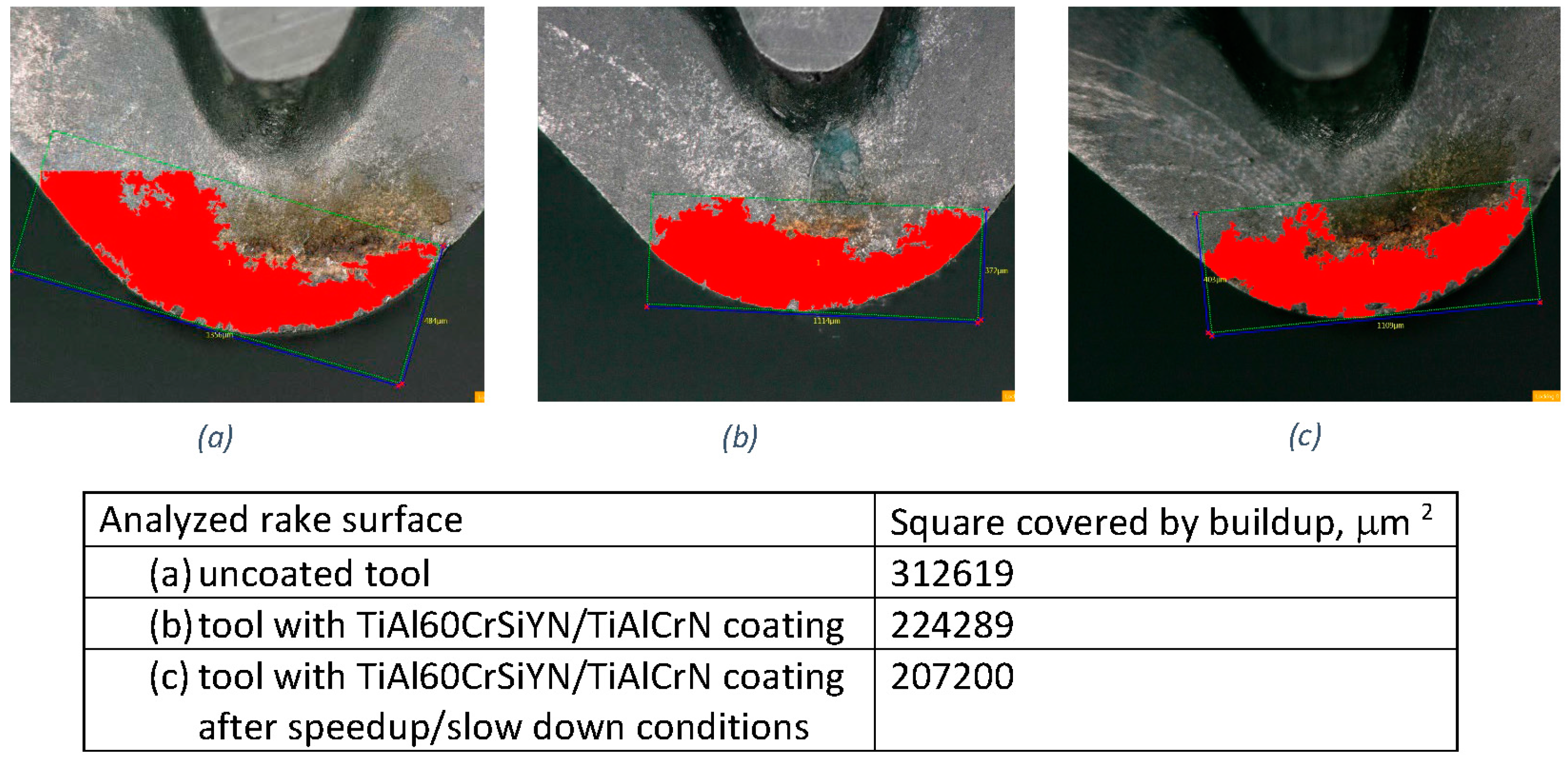
During the cutting test, tool flank wear was measured using an optical microscope (Mitutoyo-model™, Aurora, IL, USA). The covered area (build up) on the tool rake surface was measured at a cutting length of 8000 m. For this analysis the digital microscope model VHX 5000 series by Keyence (Keyence Corp., Osaka, Japan) was employed.
The chip compression ratio was determined according to the standard methods [17]. The shear angle and the cutting force were determined by the conventional methods [17]. In addition, the hardness on the chip cross-section was evaluated using Shimadzu Micro-hardness Tester using Vickers indenter. In these tests the applied load was 0.05 kg for 10 s.
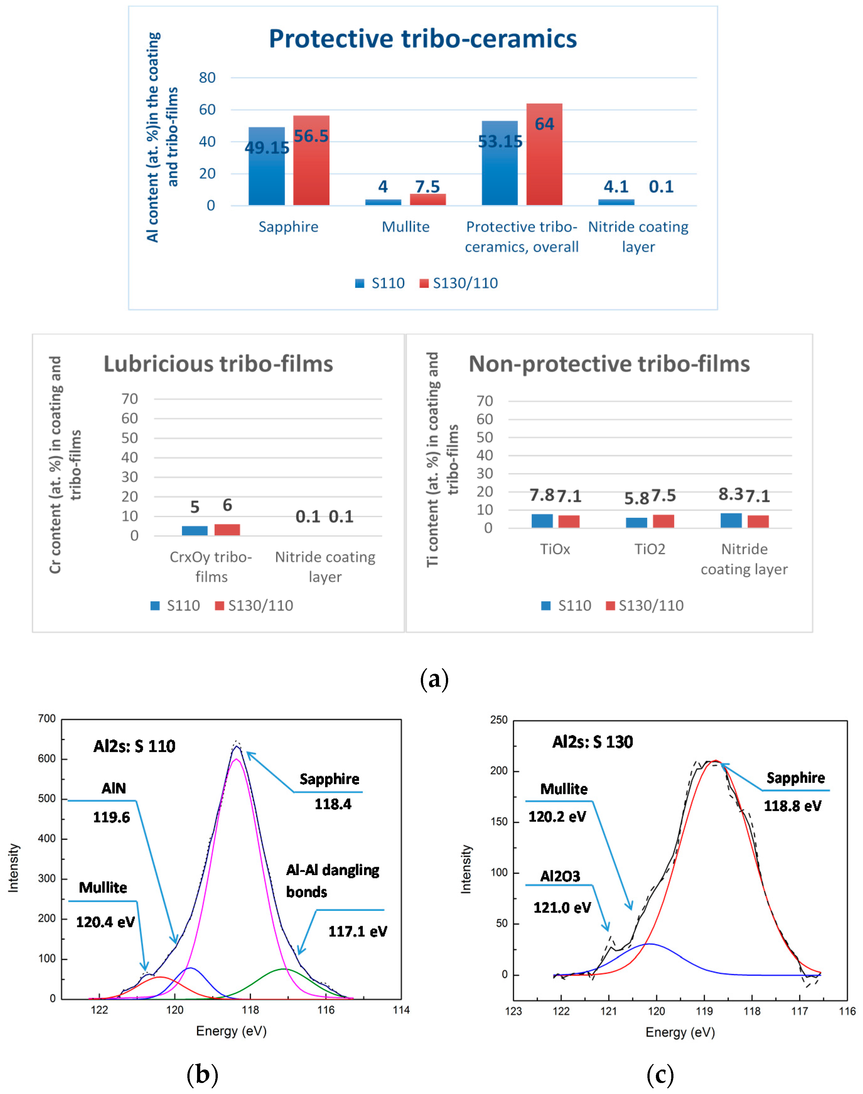
The structural and phase transformation at the cutting tool/workpiece interface, as well as the chemical nature of the tribo-films formed, were determined by X-ray Photoelectron Spectroscopy (XPS) on a Physical Electronics (PHI) Quantera II (Physical Electronics Inc., Chanhassen, MN, USA) equipped with a hemispherical energy analyzer and an Al anode source for X-ray generation and a quartz crystal monochromator for focusing the generated X-rays. A monochromatic Al K-α X-ray (1486.7 eV) source was operated at 50 W–15 kV. The system base pressure was as low as 1.0 × 10⁻⁹ Torr, with an operating pressure that did not exceed 2.0 × 10⁻⁸ Torr. Before any spectra were collected from the samples, the samples were sputter-cleaned for four minutes using a 4 kV Ar+ beam. A pass energy of 280 eV was used to obtain all survey spectra, while a pass energy of 69 eV was used to collect all high-resolution data. All spectra were obtained at a 45° take off angle and utilized a dual beam charge compensation system to ensure the neutralization of all samples. The instrument was calibrated using a freshly cleaned Ag reference foil, where the Ag 3d5/2 peak was set to 368 eV. All data analyses were performed using PHI Multipak version 9.4.0.7 software. Spots for the high resolution (HR) HR analysis were selected based on careful preliminary investigation of general photoelectron spectra of the worn surface close to the buildup edge area.

4. Results

4.1. Investigation of Cutting Tool Wear Performance

Results on wear resistance of uncoated cutting tool and a few coated tools are presented in Figure 2. The coatings tested were as follows: previous art adaptive coatings (AlTiN) [2] used for machining of stainless steels and the next generation of adaptive TiAl55CrSiYN/TiAlCrN coatings [20,22]. It is shown that adaptive coatings can improve tool life, as compared to the uncoated samples, by 32%, and with optimized machining conditions, up to 67%.
The data presented in Figure 3 exhibits flank wear vs. length of cut data for uncoated and coated cutting tools with varying machining conditions. The highest wear rate was observed on the uncoated insert.
SEM image of the cutting edge indicates intensive accumulation of the workpiece material, facilitating intensive buildup edge formation. The literature indicates that the buildup is a composite material, which consists mostly of Fe, and also contains some hard carbides and various oxides [4]. Such a structure, on the one hand, definitely has protective/lubricating properties, but, on the other hand, due to its permanent growth over time, it behaves like an avalanche, leading to deep surface damage and catastrophic failure of the entire tribo-system (Figure 1).
Application of adaptive TiAl60CrSiYN/TiAlCrN nano-multilayer coating [20] noticeably reduces the wear rate and diminishes accumulation of the workpiece material on the friction surface. This leads to formation of smaller and thinner buildup (Figure 3).
It was shown, in our previous studies, that, for machining of difficult-to-cut materials, an initial short-term increase in the cutting speed during the running-in stage noticeably improves the life of a tool with a TiAl55CrSiYN/TiAlCrN nano-multilayer coating [22]. This is because, under initial cutting at a higher speed, enhanced formation of protective/lubricious tribo-ceramic films on the friction surface takes place, with the subsequent slowdown in speed preventing total wearing out of the beneficial tribo-films. In this way, the tribo-film formation can be enhanced at the start of the process of cutting, and the benefits of the formation of these films can be realized over the life of the tool. In current research, this strategy was applied for the machining of SDSS. First of all, to amplify the formation of protective tribo-ceramic films, a higher aluminum content coating TiAl60CrSiYN/TiAlCrN nano-multilayer was chosen [20]. The wear intensity curve shows that this strategy works quite well for the machining of SDSS (Figure 3), as indicated by the following observations: (1) tool life of the coating with increased Al content (60 at.% instead of 55 at.%) was higher, and (2) within the area of intensifying external conditions (speed is 130 m/min instead of 110 m/min), the adaptive response of the surface engineered layer system is enhanced. This leads to a strong drop in wear rate during the initial running-in stage and an overall improvement of tool life (Figure 3). SEM data show that thin, spot-like buildups form (see insert in Figure 3). Therefore, the scale and intensity of the avalanche-like process is strongly reduced. Optical imaging of the rake surface (Figure 4), combined with the quantitative evaluation of the area of worn rake surface covered by the buildup, confirms the data presented in Figure 3.

4.2. Investigation of Tribological Performance through Chip Characteristics Studies

Results presented in Figure 4 are in good agreement with the tribological data evaluated through chip characteristics, as shown in Table 2.
Chip undersurfaces are excellent fingerprints of the surface phenomenon. These data were combined with the collection of frictional (cutting) force data at the very beginning of the cutting process. SEM images of chip undersurfaces are presented in Figure 5. They show that the typical stick-slip phenomenon [1] is taking place on the undersurface of the chips formed by the uncoated tools (Figure 5a), which is directly related to the concept of self-organized criticality [7,8]. Spikes of frictional forces are most intensive for the uncoated cutting tool. This is directly related to stick-slip phenomenon (wave-like patterns on the chip undersurface indicated by arrows in Figure 5a). This phenomenon is strongly diminished for the coated tool: Wave like patterns and spikes in cutting forces are less intensive (Figure 5b) and practically eliminated (no visible wave-like patterns on the chips undersurface); small, rarely occurring spikes of the frictional forces for the coated tools with optimized machining conditions (Figure 5c), and a direct indication of significant improvement in the frictional performance.
Machining of stainless steels is characterised by severe shear stresses, resulting in high plastic deformation and elevated temperatures at the chip formation zone [5]. To evaluate the plastic deformation and microstructural changes during machining, optical metallography characterization was performed on the SDSS chip cross section. It can be observed in Figure 6 that the chip formation in the primary shear zone and chip flow over the rake face of the tool are dynamic processes, which involves slip, stick and cracking of the SDSS in the primary shear zone, resulting in serrated chip formation. During machining of SDSS, once chips slide over the rake face of the cutting tool, curved flow lines are formed due to friction at the secondary shear zone. Hence, a visible metal flow is observed at the chip/tool interface of the uncoated tools coating (Figure 6a), while metal flow is less visible for the tool with the TiAl60CrSiYN/TiAlCrN PVD coating (Figure 6b) tested at 110 m/min (sample S110), and it is further diminished for the coated tool tested at 130 m/min (sample S130), as can be seen in Figure 6c.
To further understand the details of chip flow, micro-hardness distribution measurements were performed along the cross section of the chips. The results show that the hardening takes place at the tool-chip interface for the uncoated and S110 coated tool. This is related to intensive sticking of the workpiece material to the rake tool surface (see corresponding SEM image in the insert in Figure 3). Sticking leads to intensive metal flow at the chip interface (Figure 6a). The metal flow, in turn, causes the formation of heterogeneous regions, which were observed in the microstructure of the chips produced by the uncoated coated tool, and could be identified as strain-induced martensite. It is known that plastic deformation can induce phase transformation, which is typical in superduplex stainless steels [23].
Due to this phase transformation, the hardness of the interface layer grows, resulting in a more difficult-to-machine condition. For the chips obtained from the S110 coated tool, the phenomenon is the same, but, due to the reduced sticking intensity (Figure 3 and Figure 4), martensite formation is diminished and martensite plates cannot be observed in the optical image (Figure 6b). For the S130 coated tool, on the contrary, a softening occurs at the tool/chip interface, and, conversely, a slight hardening takes place far away from the interface (Figure 6c). This favorable behavior of the chips produced by S130 coated tool is related to the enhanced formation of a very large amount of protective tribo-ceramics on the cutting tool rake surface, as shown in Figure 7. In case of the S130 sample, the outer tribo-ceramic layer acts as a thermal barrier, decreasing the heat flow from the cutting zone towards the tool surface [22]. Thus, a greater amount of heat is transferred through the chip, softening the secondary plastic deformation zone (see Figure 6c). In addition, the S130 coated tool shows the best-measured in situ tribological characteristics during cutting [1], such as the highest compression ratio and highest shear angle (Table 2). Since all the cutting parameters are constant in this investigation, a high compression ratio indicates a higher shear angle (Table 2). Higher shear angle leads to lower shear force and lower frictional forces (Table 2) during turning.

4.3. Investigation the Tribo-Films Formation

Tribo-film formation on the friction surface, being the result of tribo-oxidation of the coating layer under operation, plays a critical role in the adaptive response of the surface engineered system, especially under extreme friction conditions [2]. Different types of tribo-films form on the surface of the cutting tools with TiAl60CrSiYN/TiAlCrN multilayer coatings (Figure 7), including, mostly, sapphire and mullite thermal barrier ceramic films [15,20,22,23]; high temperature lubricious Cr oxide films; and non-protective Ti-based tribo-films [15,21,22]. A major feature of the studied adaptive TiAl60CrSiYN/TiAlCrN coatings is their ability to form a nano-scale layer of tribo-ceramics with an extremely high protective ability [15], radically altering the thermal properties on the friction surface [21]. That is why this research mainly focuses on investigating the effects of protective, thermal barrier tribo-ceramics, which predominantly control the adaptive performance of the surface engineered layer [15,21]. They play an unprecedented role when system operates under the catastrophic seizure conditions associated with SDSS machining. XPS studies of the surface layer allow us to determine the chemical and phase compositions of the wear products, which possess the greatest stability, and remain on the surface during the running-in stage (Figure 7). The primary difference in wear behavior of the multilayer nano-materials during varying machining conditions lies in the accelerated beneficial tribo-oxidation on the surface of the multilayer TiAl60CrSiYN/TiAlCrN coating along with initial acceleration (Figure 7). Tribo-film phase compositions at different cutting conditions are shown in Figure 7a. Figure 7b,c presents detailed data on the phase composition of the worn surface of cutting tools with the multilayer TiAl60CrSiYN/TiAlCrN coating during the running-in stage of wear (after 1000 m of turning). Figure 7b,c shows the components of photoelectron lines Al2s, corresponding to the different types of chemical bonds of aluminum in simple and complex oxide films and nitride coatings. Previously, such meta-stable phases have been observed on the worn surface of coated tools [2]. Chemical shifts in the Al2s component regulate the phase composition of aluminum-based compounds on the worn surface. Al-Si-O bonds generate in the composite oxide with the mullite structure. Al-O bonds are typical of the Al2O3 composite and Al-N bonds correspond to the spots of the initial nitride coating, which did not undergo oxidation during cutting. Figure 7b,c exhibits the difference in tribo-chemical behavior of the multilayer coating under varying machining conditions. A large amount of protective tribo-ceramics form on the surface of the coated tool at a lower cutting speed of 110 m/min (Figure 7a,b, S110 sample). However, a certain amount of Al-Al dangling bonds appear, which indicates the anamorphous-like structure of the layer [15]. Some amount of the initial nitride phase is also present (Figure 7a,b). A substantially greater amount of sapphire and, especially, mullite tribo-films, form on the worn surface of the multilayer under intensifying operating conditions (Figure 7a,c). A greater quantity of the mullite phase with a reduced thermal conductivity [24] leads to additional protection of the friction surface. No nitride phase was identified (Figure 7a) in the S130 sample, indicating complete tribo-oxidation of the friction surface. This directly affects the tool life and wear performance, (Figure 3 and Figure 4), demonstrating the efficiency of the selected strategy of self-organized criticality control.

5. Conclusions

A control strategy of self-organized criticality is presented, using an example of extreme tribological conditions which occur under machining of hard to cut austenitic superduplex stainless steel SDSS UNS32750 associated with intensive build-up edge formation. Machining of this material develops under conditions of intensive seizure at the tool/chip/workpiece interface, which represents a catastrophic wear mode. This leads to a highly surface damaging process: a periodical breakage of the build-ups, eventually resulting in catastrophe (complete loss of workability) of the tribo-system. The dynamic process of build-up edge formation is similar to that of avalanches. It is governed by stick-slip phenomenon during friction and associated with the self-organized critical process. Thermodynamic analysis was undertaken with the aim of understanding a number of very complex and interconnected tribological mechanisms that take place within the tool/buildup/workpiece tribo-system during cutting with buildup edge formation. The novelty of thermodynamic modeling is the investigation of entropy production during friction in machining combined with surface energy analysis. The proposed model enables prediction of the majority of complex phenomena observed in the experimental part of the research. SEM studies of the worn surface of the cutting tools combined with investigation of chip undersurface; chip cross-section characterization and frictional (cutting) forces analysis confirm hypothesis of self-organized criticality. A method of control over the self-organized critical process is developed via the application of adaptive TiAl60CrSiYN/TiAlCrN thin film PVD coating onto the carbide tool. This coating possesses elevated aluminum content, enabling protective tribo-film formation on the friction surface under operation. Moreover, the machining process optimization (acceleration in the beginning of the running-in stage of wear, with consequent slowdown to prevent excessive wear rate) allows to even further enhance self-protective tribo-film formation. XPS studies of dynamic nano-scale tribo-films demonstrate that this strategy results in a reduction of the scale of the build ups, leading to wear performance improvement. Obtained results demonstrated a novel approach of control over self-organized criticality processes, presented through the enhanced adaptive performance of a surface engineered tribo-system, which enables reduction of the scale and frequency of buildup edges, which are similar to avalanches.

Acknowledgments

This work was partially supported by the Russian Scientific Foundation No. 15-19-00217 (Thermodynamic analysis) and No. 14-19-01033 (Results).

Author Contributions

German Fox-Rabinovich designed the experiments and wrote the paper, Jose M. Paiva performed the cutting experiments, Iosif Gershman performed theoretical modeling, Myriam Aramesh performed theoretical modeling and experimental studies of tribological performance, Danielle Cavelli performed XPS studies, Kenji Yamamoto performed coatings deposition and structure characterization, Goulnara Dosbaeva performed metallographic and SEM studies and Stephen Veldhuis designed cutting experiments and edited the paper. All authors have read and approved the final manuscript.

Conflicts of Interest

The authors declare no conflict of interest.

References

  1. Trent, E.M.; Wright, P.K. Metal Cutting, 4th ed.; Butterworth–Heinemann: Oxford, UK, 2000; p. 352. [Google Scholar]
  2. Fox-Rabinovich, G.; Totten, G.E. Self-Organization during Friction: Advanced Surface-engineered Materials and Systems Design; CRC Press: Boca Raton, FL, USA, 2006. [Google Scholar]
  3. Kabaldin, Y.G.; Kojevnikov, N.V.; Kravchuk, K.V. HSS cutting tool wear resistance study. J. Frict. Wear 1990, 11, 130–135. [Google Scholar]
  4. Fox-Rabinovich, G.S.; Kovalev, A.I. Self-Organization and Structural Adaptation during Cutting and Stamping Operations. In Self-Organization during Friction: Advance Surface Engineered Materials and Systems Design; Fox-Rabinovich, G.S., Totten, G., Eds.; CRC Press: Boca Raton, FL, USA, 2006; pp. 151–167. [Google Scholar]
  5. Ernst, H. Machining of Metals; American Society for Metals: Geauga County, OH, USA, 1938; p. 177. [Google Scholar]
  6. Bak, P. How Nature Works: The Science of Self-Organized Criticality; Springer: Berlin/Heidelberg, Germany, 1999; p. 155. [Google Scholar]
  7. Feder, H.J.S.; Feder, J. Self-Organized Criticality in a Stick-Slip Process. Phys. Rev. Lett. 1991, 66, 2669–2672. [Google Scholar] [CrossRef] [PubMed]
  8. Wang, Q.; Lu, C.; Ye, G.G.; Dai, L.H. Modeling the tunned criticality in stick-slip friction during metal cutting. Model. Simul. Mater. Sci. Eng. 2015, 23, 055013. [Google Scholar] [CrossRef]
  9. Cajueiro, D.O.; Andrade, R.F.S. Controlling self-organized criticality in sandpile models. Phys. Rev. E 2010, 81, 015102. [Google Scholar] [CrossRef] [PubMed]
  10. Cajueiro, D.O.; Andrade, R.F.S. Controlling self-organized criticality in complex networks. Eur. Phys. J. B 2010, 77, 291–296. [Google Scholar] [CrossRef]
  11. Cajueiro, D.O.; Andrade, R.F.S. Dynamical programming approach for controlling the directed Abelian Dhar-Ramaswamy model. Phys. Rev. E 2010, 82, 031108. [Google Scholar] [CrossRef] [PubMed]
  12. Fox-Rabinovich, G.S.; Gershman, I.; El Hakim, M.A.; Shalaby, M.A.; Krzanowski, J.E.; Veldhuis, S.C. Tribofilm Formation as a Result of Complex Interaction at the Tool/Chip Interface during Cutting. Lubricants 2014, 2, 113–123. [Google Scholar] [CrossRef]
  13. Semenov, A.P. Friction and Adhesive Interaction of Refractory Materials at High Temperatures; Nauka: Moscow, Russia, 1972; p. 160. [Google Scholar]
  14. Jacobson, S.; Hogmark, S. Tribofilms-On the crucial importance of tribologically induced surface modification. In Recent Developments in Wear Prevention, Friction and Lubrication; Nikas, G.K., Ed.; Research Signpost: Kerala, India, 2010; p. 19. [Google Scholar]
  15. Fox-Rabinovich, G.; Kovalev, A.; Veldhuis, S.; Yamamoto, K.; Endrino, J.L.; Gershman, I.S.; Rashkovskiy, A.; Aguirre, M.H.; Wainstein, D.L. Spatio-Temporal Behaviour of Atomic-Scale Tribo-Ceramic Films in Adaptive Surface Engineered Nano-Materials. Sci. Rep. 2015, 5, 8780. [Google Scholar] [CrossRef] [PubMed]
  16. Bershadski, L.I. Boris Ivanovich Kostetski and general conception in tribology. J. Frict. Wear 1993, 14, 6–19. (In Russian) [Google Scholar]
  17. Bershadsky, L.I. On self-organizing and concept of tribosystem self-organizing. J. Frict. Wear 1992, 13, 101–114. [Google Scholar]
  18. Kostetsky, B.I. Evolution of structural and phase state and mechanism of self-organization in materials at external friction. J. Frict. Wear 1993, 14, 120–129. [Google Scholar]
  19. Fox-Rabinovich, G.S.; Gershman, I.S.; Yamamoto, K.; Biksa, A.; Veldhuis, S.C.; Beake, B.D.; Aguirre, M.H.; Kovalev, A.I. Self-organization during friction in complex surface engineered tribosystems. Entropy 2010, 12, 275–288. [Google Scholar] [CrossRef]
  20. Fox-Rabinovich, G.S.; Beake, B.D.; Yamamoto, K.; Aguirre, M.H.; Veldhuis, S.C.; Dosbaeva, G.; Elfizy, A.; Biksa, A.; Shuster, L.S. Structure, properties and wear performance of nano-multilayered TiAlCrSiYN/TiAlCrN coatings during machining of Ni-based aerospace superalloys. Surf. Coat. Technol. 2010, 204, 3698–3706. [Google Scholar] [CrossRef]
  21. Fox-Rabinovich, G.S.; Endrino, J.L.; Agguire, M.H.; Beake, B.D.; Veldhuis, S.C.; Kovalev, A.I.; Gershman, I.S.; Yamamoto, K.; Losset, Y.; Wainstein, D.L.; et al. Mechanism of adaptability for the nano-structured TiAlCrSiYN-based hard PVD coatings under extreme frictional conditions. J. Appl. Phys. 2012, 111, 064306. [Google Scholar] [CrossRef]
  22. Yuan, J.; Yamamoto, K.; Covelli, D.; Tauhiduzzaman, M.; Arif, T.; Gershman, I.S.; Veldhuis, S.C.; Fox-Rabinovich, G.S. Tribo-films control in adaptive TiAlCrSiYN/TiAlCrN multilayer PVD coating by accelerating the initial machining conditions. Surf. Coat. Technol. 2016, 294, 54–61. [Google Scholar] [CrossRef]
  23. Chiu, P.K.; Weng, K.L.; Wang, S.H.; Yang, J.R.; Huanga, Y.S.; Fang, J. Low-cycle fatigue-induced martensitic transformation in SAF 2205 duplex stainless steel. Mater. Sci. Eng. A 2005, 398, 349–359. [Google Scholar] [CrossRef]
  24. Mah, T.I.; Mazdiyasni, K.S. Mechanical Properties of Mullite. J. Am. Ceram. Soc. 1983, 66, 699–703. [Google Scholar] [CrossRef]
Figure 1. Schematic presentation of superduplex stainless steel (SDSS) machining with buildup edge formation using an uncoated cemented carbide cutting tool. Wear resistance data with progressive Scanning Electron Microscope (SEM) studies of avalanche-like phenomena on the friction surface are presented.
Entropy 18 00290 g001
Figure 2. Tool life data of SDSS machining (provided by SANDVIK Group, San Paulo, Brazil) for uncoated and various coated cutting tools.
Entropy 18 00290 g002
Figure 3. Wear resistance data (flank wear vs. length of cut) of SDSS machining for uncoated and coated cutting tools with varying machining conditions.
Entropy 18 00290 g003
Figure 4. Intensity of buildup formation on the rake surface during machining of SDSS using uncoated and coated cutting tools with varying machining conditions: (a) uncoated tool; (b) tool with TiAl60CrSiYN/TiAlCrN coating; (c) tool with TiAl60CrSiYN/TiAlCrN multilayer coating, optimized machining conditions (initial speed up/slow down strategy, see Experimental Section).
Entropy 18 00290 g004
Figure 5. Chip undersurface at different magnifications (400× and 1000×) and cutting forces data: (a) uncoated tool; (b) tool with TiAl60CrSiYN/TiAlCrN multilayer coating; (c) tool with TiAl60CrSiYN/TiAlCrN multilayer coating, optimized machining conditions (initial speed up/slow down strategy, see Experimental Section).
Entropy 18 00290 g005
Figure 6. Chip cross-sections: (a) uncoated insert; (b) insert with TiAl60CrSiYN/TiAlCrN multilayer coating, speed 110 m/min; (c) insert with TiAl60CrSiYN/TiAlCrN multilayer coating, speed 130 m/min.
Entropy 18 00290 g006
Figure 7. XPS data for tribo-films formed on the worn surface of multilayer TiAl60CrSiYN/TiAlCrN thin film coating during running-in stage (after turning of 1000 m): (a) comparison of tribo-film phase composition at different cutting conditions; (b,c) HR Photoelectron Al2s spectra on the rake surface of the worn coated tool tested at 110 m/min (b) and 130 m/min (c).
Entropy 18 00290 g007
Table 1. The characteristics of the TiAlCrSiYN/TiAlCrN coatings.
Coatings CharacteristicsValues
Crystal StructureFCC nano-crystalline
Grain size (nm)20–40
Coating thickness (µm)3
Nano-layer thickness (nm)20–40
Micro hardness at RT (GPa)30
Table 2. Tribological performance of analyzed tools evaluated through chips characteristics.
Tool/Cutting ConditionsTribological Characteristics
ToolV Speed (m/min)r (Chip Compression Ratio)Φ (Shear Angle)Fp (Cutting Force, Average)µ (Coefficient of Friction)
Uncoated1100.72485207139.8559651995.430.409887 ± 0.02
Coated1100.79545454542.9919289679.920.28705 ± 0.014
Coated1300.86267605645.7980430633.510.183605 ± 0.09

