
Experimental Study of Single Phase Flow in a Closed-Loop Cooling System with Integrated Mini-Channel Heat Sink


Abstract
:1. Introduction
2. Experimental Apparatus
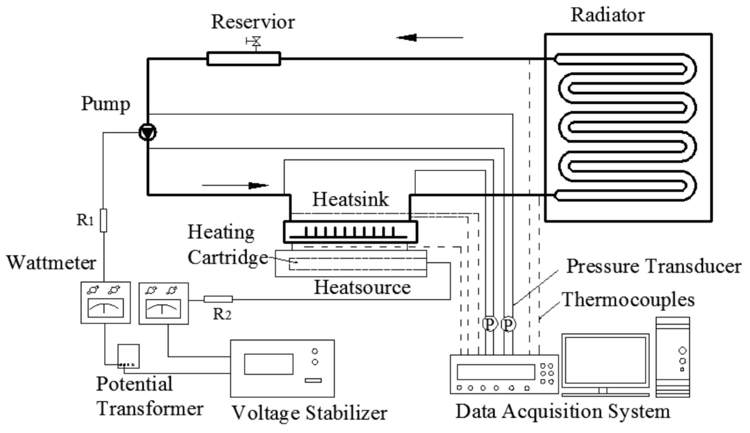
2.1. Experimental System
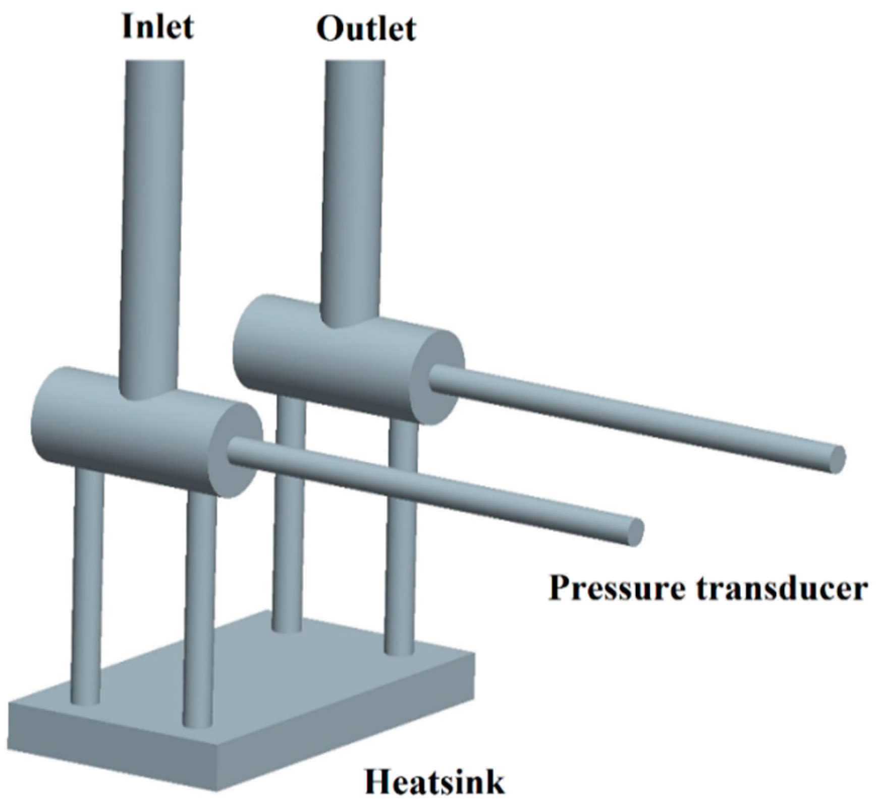
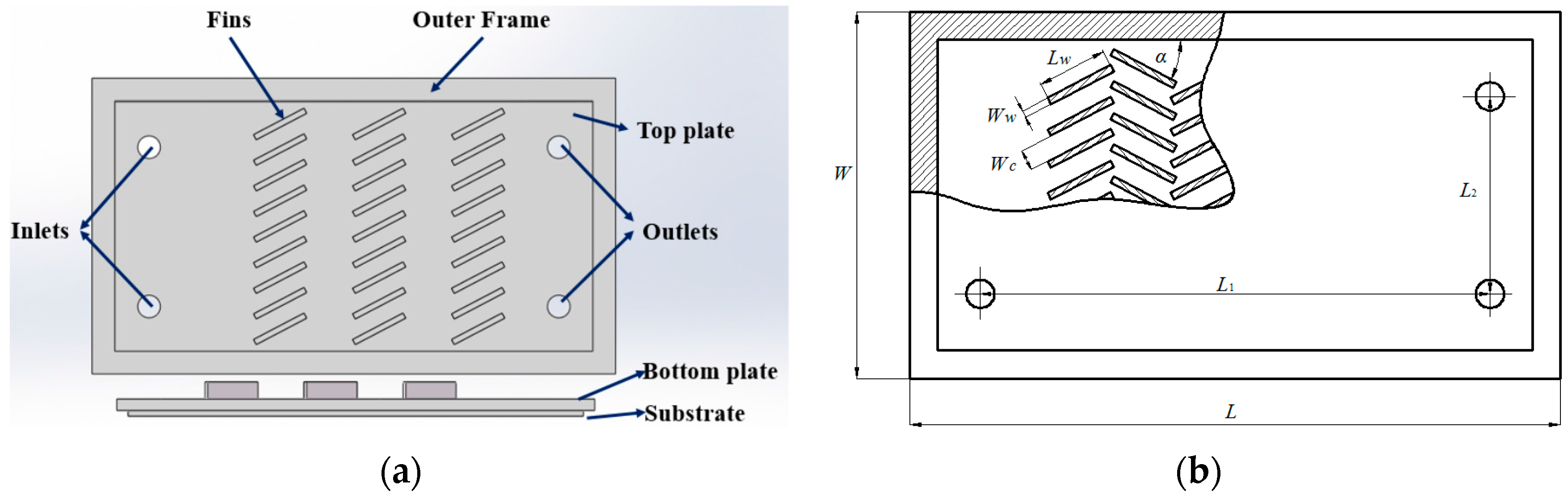
2.2. Design of the Mini-Channel Heat Sink
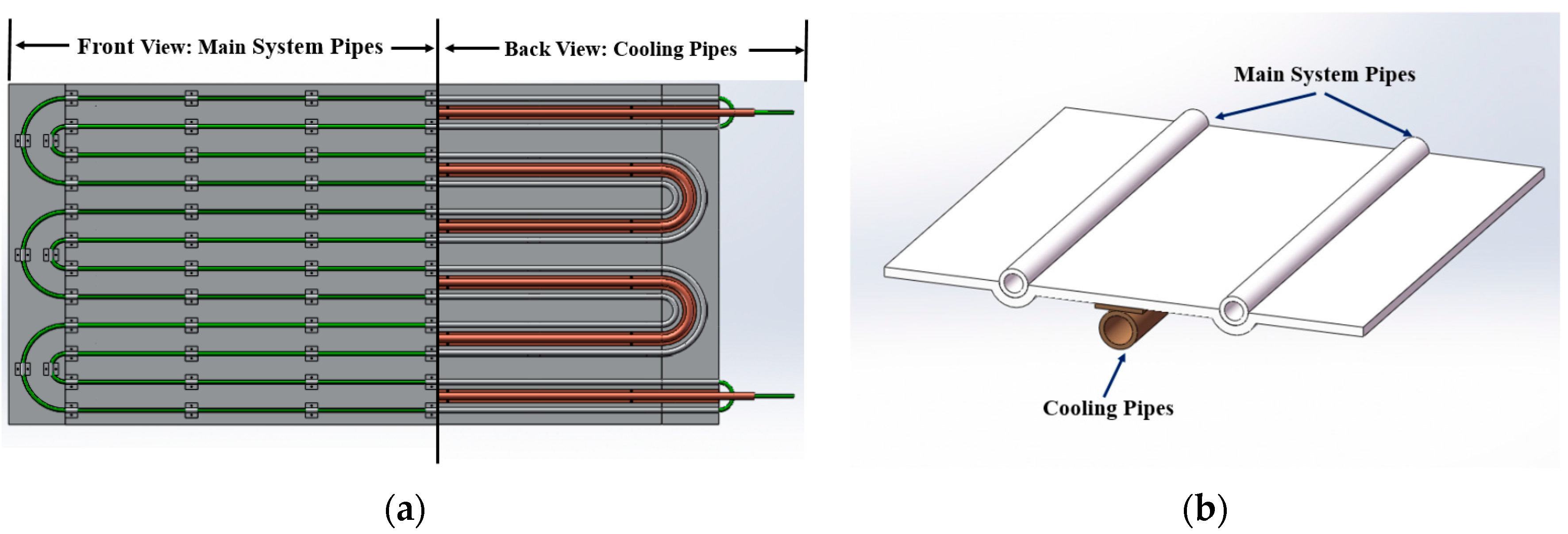
2.3. Design of Radiator
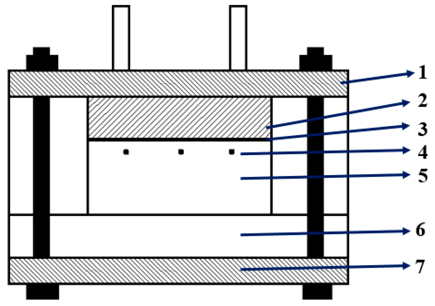
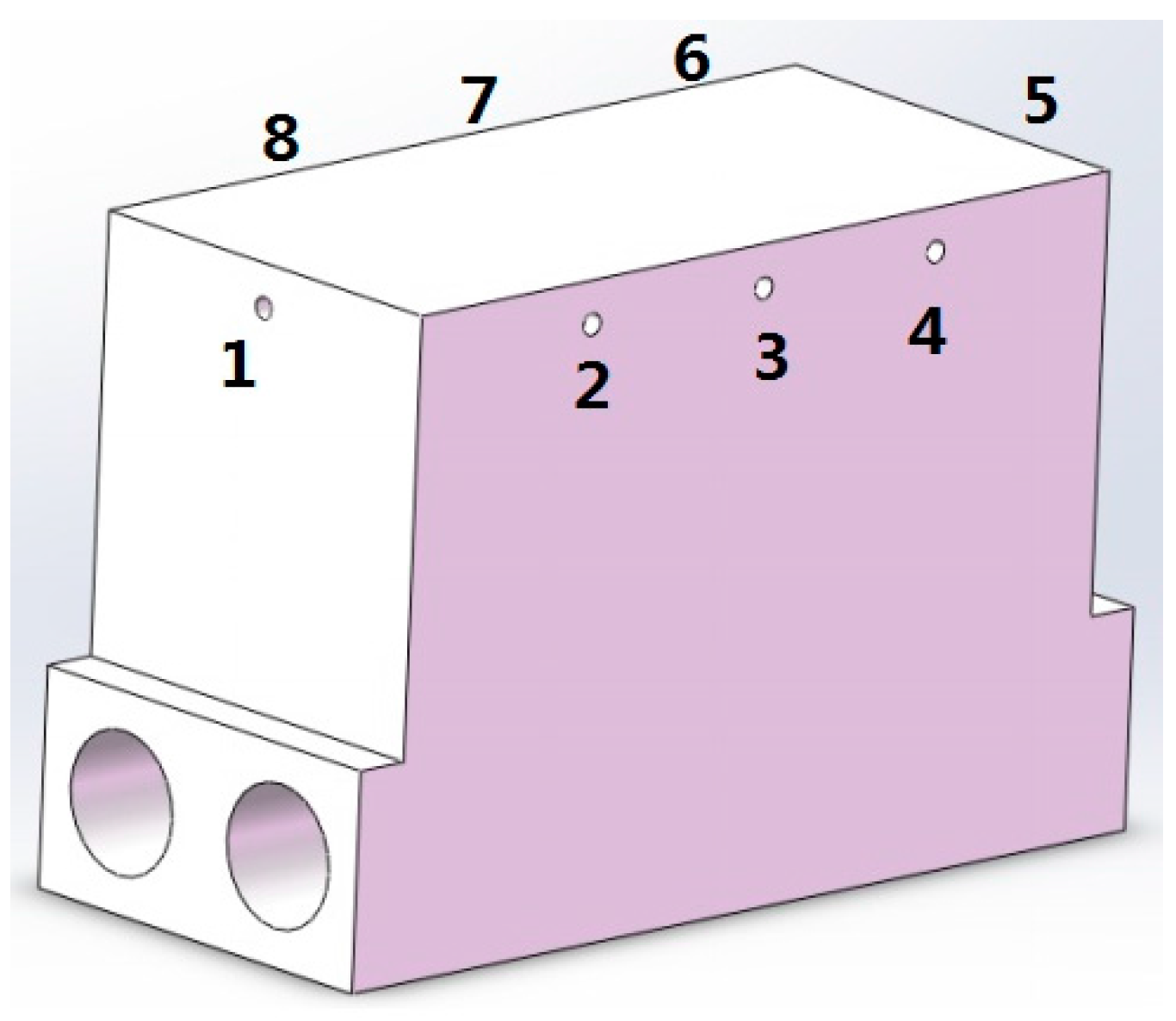
2.4. Design of the Heat Source
2.5. Temperature and Pressure Testing
2.6. Data Reduction
2.7. Uncertainty in Experimental Data
3. Results and Discussions
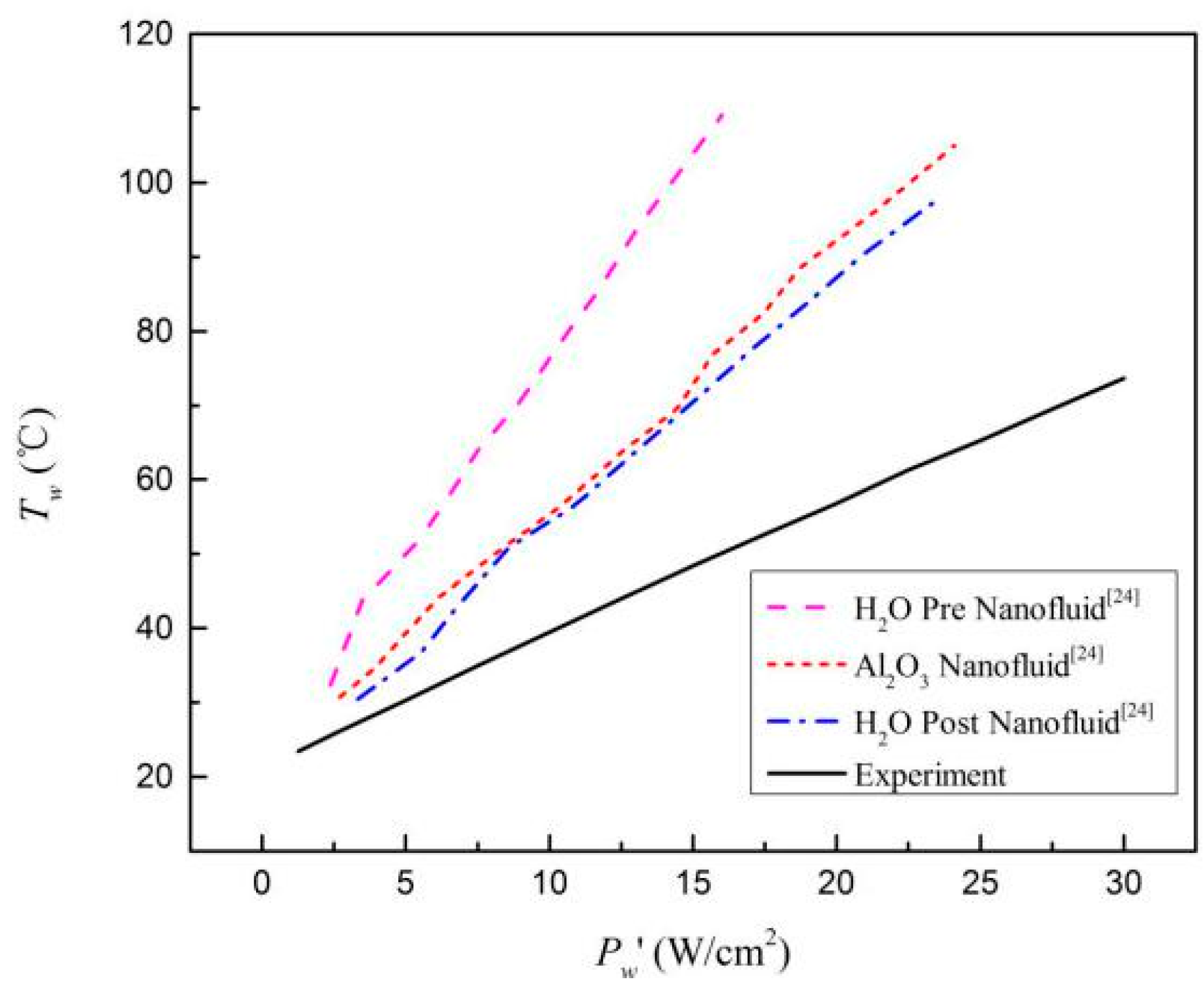
3.1. Heat Sink Performance
3.2. The Closed-Loop System Performance
4. Conclusions
- (a)
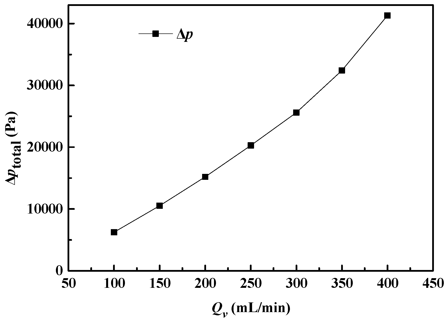
- The system has a transportation distance of more than 5 m with the system pressure drop about 41.31 kPa when the system volume flow rate is 400 mL/min.
- (b)
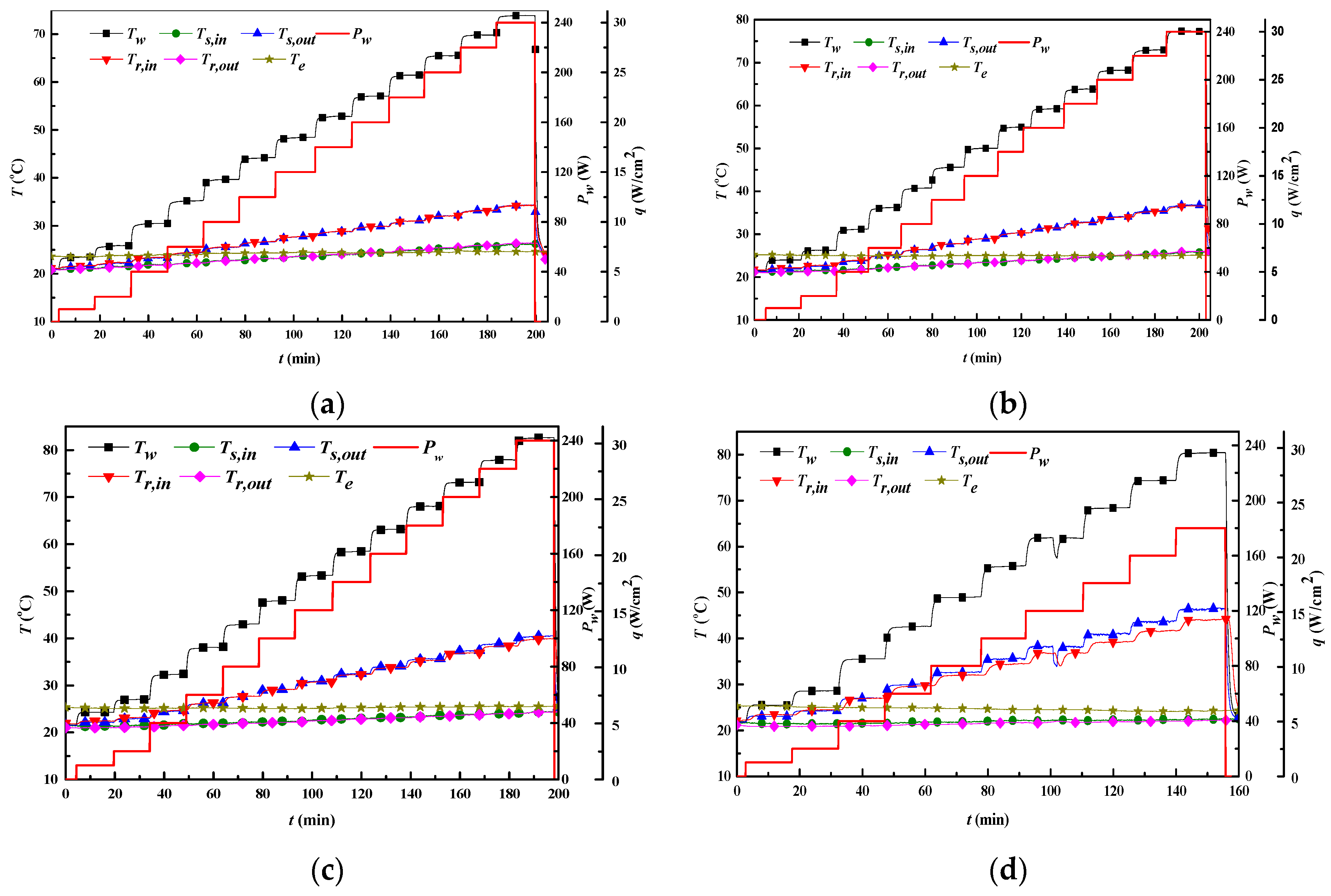
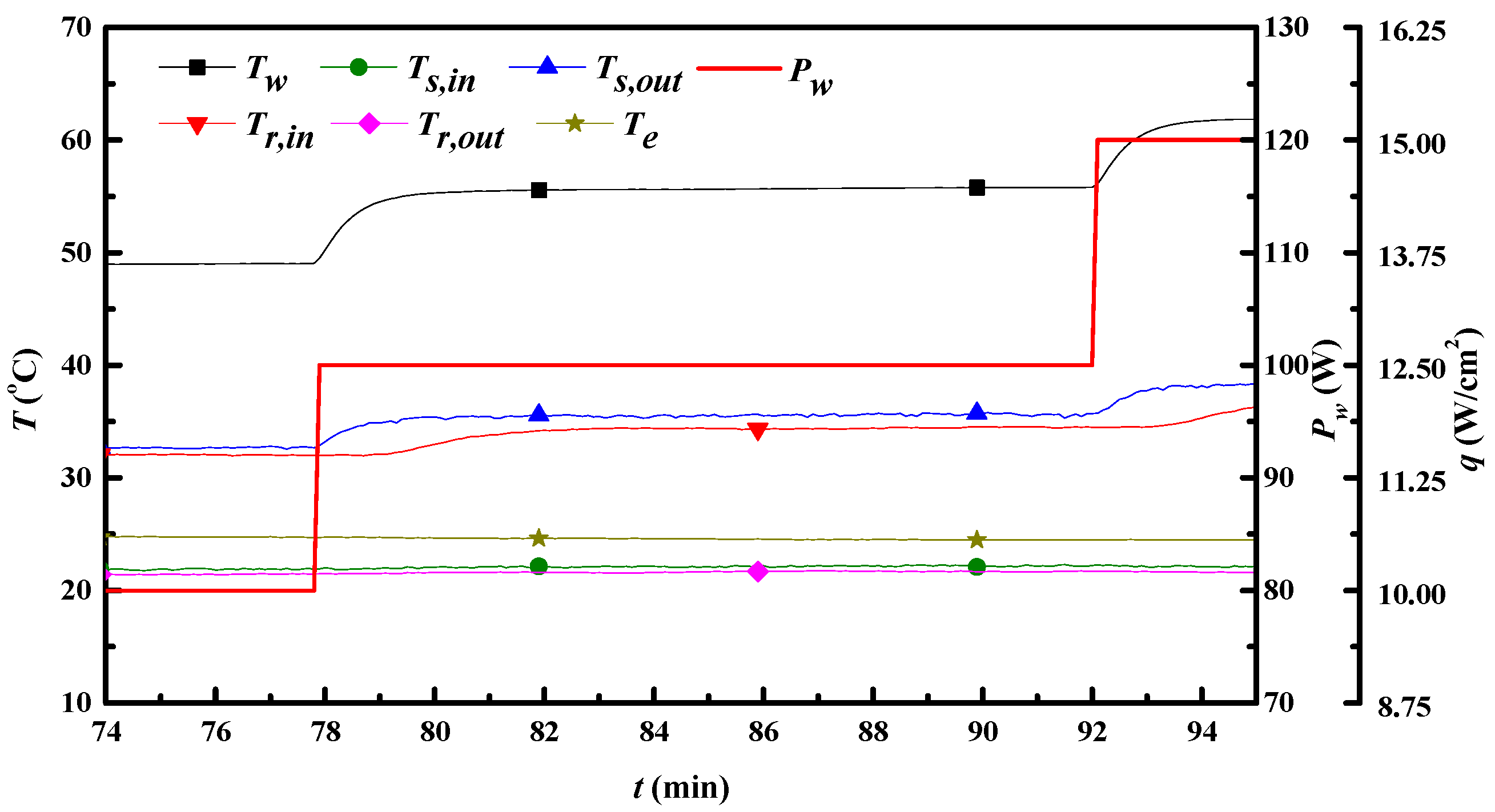
- The system has a cooling capability of 240 W when the base temperature is below 80 °C.
- (b)
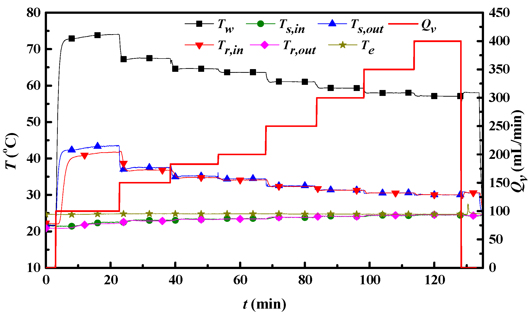
- When the base temperature is 77.3 °C and the heat source power is 240 W (corresponding to a heat flux of 30 W/cm2), the volume flow rate can be controlled as low as 300 mL/min.
Acknowledgments
Author Contributions
Conflicts of Interest
Abbreviations
| h | heat transfer coefficient (W/m2·K) |
| L | length of the outer frame (mm) |
| L1 | distance between inlet and outlet (mm) |
| L2 | distance between two outlets (or inlets) (mm)) |
| Lw | length of the fins (mm) |
| Δpsink | pressure drop between inlet and outlet of the heat sink (Pa) |
| Δptotal | pressure drop in whole system pipes (Pa) |
| Pw | input heating power (W) |
| q | heat flux at the substrate (W/cm2) |
| Qv | volume flow rate (mL/min) |
| t | time (min) |
| T | temperature (°C) |
| Te | ambient temperature (°C) |
| Tl | average liquid temperature (°C) |
| Tr,in | temperature at the inlet of the radiator (°C) |
| Tr,out | temperature at the outlet of the radiator (°C) |
| Ts,in | temperature at the inlet of the heat sink (°C) |
| Ts,out | temperature at the outlet of the heat sink (°C) |
| Tw | base temperature (°C) |
| W | width of the outer frame (mm) |
| Wc | distance between two fins, the width of the channel (mm) |
| Ww | width of the fins (mm) |
Greek Symbol
| α | the arrangement angel between fins and heat sink side (°) |
References
- Hu, Y.; Zeng, L.; Minnich, A.J.; Dresselhaus, M.S.; Chen, G. Spectral Mapping of Thermal Conductivity through Nanoscale Ballistic Transport. Nat. Nanotechnol. 2015, 10, 701–706. [Google Scholar] [CrossRef] [PubMed]
- Zeng, L.; Collins, K.C.; Hu, Y.; Luckyanova, M.N.; Maznev, A.A.; Huberman, S.; Chiloyan, V.; Zhou, J.; Huang, X.; Nelson, K.A.; Chen, G. Measuring phonon mean free path distributions by probing quasiballistic phonon transport in grating nanostructures. Sci. Rep. 2015, 5. [Google Scholar] [CrossRef] [PubMed]
- Zeng, L.; Chen, G. Disparate quasiballistic heat conduction regimes from periodic heat sources on a substrate. J. Appl. Phys. 2014, 116, 064307. [Google Scholar] [CrossRef]
- Zeng, L.; Chiloyan, V.; Huberman, S.; Maznev, A.A.; Peraud, J.-P.M.; Hadjiconstantinou, N.G.; Nelson, K.A.; Chen, G. Monte Carlo study of non-diffusive relaxation of a transient thermal grating in thin membranes. Appl. Phys. Lett. 2016, 108, 063107. [Google Scholar] [CrossRef]
- Chiloyan, V.; Zeng, L.; Huberman, S.; Maznev, A.A.; Nelson, K.A.; Chen, G. A variational approach to extracting the phonon mean free path distribution from the spectral Boltzmann transport equation. 2015. arXiv:1511.08989. [Google Scholar] [CrossRef]
- Tuckerman, D.B.; Pease, R. High-performance heat sinking for VLSI. IEEE Electron Device Lett. 1981, 2, 126–129. [Google Scholar] [CrossRef]
- Vafai, K.; Zhu, L. Analysis of two-layered micro-channel heat sink concept in electronic cooling. Int. J. Heat Mass Transf. 1999, 42, 2287–2297. [Google Scholar] [CrossRef]
- Colgan, E.G.; Furman, B.; Gaynes, M.; Graham, W.S.; LaBianca, N.C.; Magerlein, J.H.; Polastre, R.J.; Rothwell, M.B.; Bezama, R.; Choudhary, R. A practical implementation of silicon microchannel coolers for high power chips. IEEE Trans. Compon. Packag. Technol. 2007, 30, 218–225. [Google Scholar] [CrossRef]
- Peng, X.; Peterson, G. Convective heat transfer and flow friction for water flow in microchannel structures. Int. J. Heat Mass Transf. 1996, 39, 2599–2608. [Google Scholar] [CrossRef]
- Kandlikar, S.G.; Grande, W.J. Evaluation of single phase flow in microchannels for high heat flux chip cooling—Thermohydraulic performance enhancement and fabrication technology. Heat Transf. Eng. 2004, 25, 5–16. [Google Scholar] [CrossRef]
- Steinke, M.E.; Kandlikar, S.G. Single-phase heat transfer enhancement techniques in microchannel and minichannel flows. In Proceedings of the Second International Conference on Microchannels and Minichannels, Rochester, NY, USA, 17–19 June 2004; pp. 17–19.
- Steinke, M.E.; Kandlikar, S.G. Single-phase liquid friction factors in microchannels. Int. J. Therm. Sci. 2006, 45, 1073–1083. [Google Scholar] [CrossRef]
- Li, J.; Peterson, G.P.; Cheng, P. Three-dimensional analysis of heat transfer in a micro-heat sink with single phase flow. Int. J. Heat Mass Transf. 2004, 47, 4215–4231. [Google Scholar] [CrossRef]
- Sung, M.K.; Mudawar, I. Experimental and numerical investigation of single-phase heat transfer using a hybrid jet-impingement/micro-channel cooling scheme. Int. J. Heat Mass Transf. 2006, 49, 682–694. [Google Scholar] [CrossRef]
- Liu, C.; Teng, J.-T.; Chu, J.-C.; Chiu, Y.-L.; Huang, S.; Jin, S.; Dang, T.; Greif, R.; Pan, H.-H. Experimental investigations on liquid flow and heat transfer in rectangular microchannel with longitudinal vortex generators. Int. J. Heat Mass Transf. 2011, 54, 3069–3080. [Google Scholar] [CrossRef]
- Bower, C.; Ortega, A.; Skandakumaran, P.; Vaidyanathan, R.; Phillips, T. Heat transfer in water-cooled silicon carbide milli-channel heat sinks for high power electronic applications. Trans. ASME C J. Heat Transf. 2005, 127, 59–65. [Google Scholar] [CrossRef]
- Lee, P.-S.; Garimella, S.V.; Liu, D. Investigation of heat transfer in rectangular microchannels. Int. J. Heat Mass Transf. 2005, 48, 1688–1704. [Google Scholar] [CrossRef]
- Qu, W.; Mudawar, I. Experimental and numerical study of pressure drop and heat transfer in a single-phase micro-channel heat sink. Int. J. Heat Mass Transf. 2002, 45, 2549–2565. [Google Scholar] [CrossRef]
- Qu, W.; Mudawar, I. Analysis of three-dimensional heat transfer in micro-channel heat sinks. Int. J. Heat Mass Transf. 2002, 45, 3973–3985. [Google Scholar] [CrossRef]
- Morini, G.L. Single-phase convective heat transfer in microchannels: A review of experimental results. Int. J. Therm. Sci. 2004, 43, 631–651. [Google Scholar] [CrossRef]
- Hawkins-Reynolds, E.; Le, H.; Stephan, R. Development, fabrication, and testing of a liquid/liquid microchannel heat exchanger for constellation spacecrafts. In Proceedings of the International Conference on Environmental Systems, Barcelona, Spain, 11–15 July 2010.
- Birur, G.C.; Sur, T.W.; Paris, A.D.; Shakkottai, P.; Green, A.A.; Haapanen, S.I. Micro/nano spacecraft thermal control using a MEMS-based pumped liquid cooling system. In Proceedings of the International Society for Optical Engineering (SPIE) International Symposium on Micromachining and Microfabrication, San Francisco, CA, USA, 22–25 October 2001; pp. 196–206.
- Paris, A.D.; Birur, G.C.; Green, A.A. Development of MEMS microchannel heat sinks for micro/nano spacecraft thermal control. In Proceedings of the ASME 2002 International Mechanical Engineering Congress and Exposition Microelectromechanical Systems, New Orleans, LA, USA, 17–22 November 2002.
- Bintoro, J.S.; Akbarzadeh, A.; Mochizuki, M. A closed-loop electronics cooling by implementing single phase impinging jet and mini channels heat exchanger. Appl. Therm. Eng. 2005, 25, 2740–2753. [Google Scholar] [CrossRef]
- Chein, R.; Chen, J. Numerical study of the inlet/outlet arrangement effect on microchannel heat sink performance. Int. J. Therm. Sci. 2009, 48, 1627–1638. [Google Scholar] [CrossRef]
- Kraus, A.D.; Aziz, A.; Welty, J. Extended Surface Heat Transfer; Wiley: Hoboken, NJ, USA, 2002. [Google Scholar]
- Wheeler, A.J.; Ganji, A.R. Introduction to Engineering Experimentation, 2nd ed.; Pearson Prentice Hall: Upper Saddle River, NJ, USA, 2004. [Google Scholar]
- Sohel, M.R.; Khaleduzzaman, S.S.; Saidur, R.; Hepbasli, A.; Sabri, M.F.M.; Mahbubul, I.M. An experiment investigation of heat transfer enhancement of a minichannel heat sink using Al2O3-H2O nanofluid. Int. J. Heat Mass Transf. 2014, 74, 164–172. [Google Scholar] [CrossRef]
- Tullius, J.F.; Bayazitoglu, Y. Effect of Al2O3/H2O nanofluid on MWNT circular fin structures in a minichannel. Int. J. Heat Mass Transf. 2013, 60, 523–530. [Google Scholar] [CrossRef]


| Instruments | Range | Accuracy |
|---|---|---|
| T-type thermocouples | −40 to 100 °C | 0.5 °C |
| Pressure drop transducer for heat sink | 7500 Pa | 25 Pa |
| Pressure drop transducer for total system | 130,000 Pa | 100 Pa |
| Objects | Uncertainty |
|---|---|
| Temperature | ± (0.62%–2.34%) |
| Pressure drop | ± (0.24%–4.10%) |
| Heat transfer coefficient | ± (1.41%–8.22%) |
© 2016 by the authors; licensee MDPI, Basel, Switzerland. This article is an open access article distributed under the terms and conditions of the Creative Commons by Attribution (CC-BY) license (http://creativecommons.org/licenses/by/4.0/).
Share and Cite
Ma, L.; Zhao, X.; Sun, H.; Wu, Q.; Liu, W. Experimental Study of Single Phase Flow in a Closed-Loop Cooling System with Integrated Mini-Channel Heat Sink. Entropy 2016, 18, 128. https://doi.org/10.3390/e18060128
Ma L, Zhao X, Sun H, Wu Q, Liu W. Experimental Study of Single Phase Flow in a Closed-Loop Cooling System with Integrated Mini-Channel Heat Sink. Entropy. 2016; 18(6):128. https://doi.org/10.3390/e18060128
Chicago/Turabian StyleMa, Lei, Xuxin Zhao, Hongyuan Sun, Qixing Wu, and Wei Liu. 2016. "Experimental Study of Single Phase Flow in a Closed-Loop Cooling System with Integrated Mini-Channel Heat Sink" Entropy 18, no. 6: 128. https://doi.org/10.3390/e18060128