1. Introduction
Since the National Institute of Standards and Technology (NIST) announced that Rijndael was proclaimed the winner of the Advanced Encryption Standard (AES) competition, no critical security weaknesses have been demonstrated for this algorithm until now [
1]. In addition, it has been reported that its performance implemented in software and hardware seems to be excellent across a wide range of computing environments [
2,
3]. Especially, AES in counter (CTR) or output feedback (OFB) mode can meet most requirements for stream cipher systems, so that there has been an unavoidable long-term decline for stream ciphers.
At the State of the Art in Stream Ciphers (SASC) 2004 and Asiacrypt 2004, A. shamir presented an invited lecture titled “Stream Ciphers: Dead or Alive?” [
4]. In this lecture, he pointed out that stream ciphers would survive only in some niche applications. These applications are as follows:
software-oriented applications with exceptionally high speed (e.g., routers)
hardware-oriented applications with an exceptionally small footprint (e.g., RFID, smart cards)
Stream ciphers for hardware-oriented applications with restricted resources are often designed using a linear feedback shift register (LFSR) [
5]. LFSRs are well suited for hardware implementation. They can produce sequences with large periods and good statistical properties. To generate keystreams with good statistical properties, designers usually used LFSR output sequences as follows [
6]:
use multiple LFSRs and a nonlinear combining function
use a single LFSR and nonlinear filter function
use irregular clocking of the LFSRs (clock-controlled generators)
However, these generators with LFSRs are potentially very vulnerable to algebraic attacks and side channel attacks.
An algebraic attack that uses over-defined systems of multivariate equations to recover the secret key has gained much attention. These equations are derived relating the output bits to the internal state bits for the generators. Let the size of the internal state be
l and the low degree of the equations be
d; then, the time complexity of the algebraic attack is
O(
ld)
ω, where
ω is the exponent of Gaussian reduction (
ω < 3). In the paper [
7], the value of
ω is log
27. Various algebraic attacks were first applied to block ciphers and public key cryptosystems [
8–
10]. Thereafter, these attacks have been effectively applied to LFSR-based systems [
11–
14]. In particular, Al-Hinai
et al. showed that algebraic attacks were effective against the irregularly-clocked LFSR systems in 2006 [
15]. To be secure against the algebraic attack, Kanso presented the generalized clock-controlled alternating step generator in 2009 [
16]. However, Hassanzadeh and Helleseth described an algebraic attack against this generator [
17].
Irregularly-clock-controlled shift registers are highly vulnerable against side channel attacks, such as simple power analysis and timing attacks [
18] (Chapter 7). In particular, this attack could be strongly applied to the shrinking generator and cascade generator, which had resistance to an algebraic attack. To overcome these attacks, new clock-controlled generators were proposed in the European ECRYPT eSTREAM project, such as cascade the jump-controlled generator (named Pomaranch) and the mutual clock-controlled generator (named Mickey) [
19]. However, the algebraic attack could be applied on these generators [
20].
In this paper, we present a new clock-controlled generator: the switching generator. This generator can be resistant to algebraic attack by maintaining both secure properties and the efficiency of traditional clock-controlled generators. Especially, we can protect this generator against side channel attacks by choosing some parameters easily.
2. Clock-Controlled Generators
LFSRs are known to allow fast implementation on hardware and produce sequences with large periods and good statistical properties. However, the inherent linearity of these sequences results in susceptibility to algebraic attacks. That is the fundamental reason why LFSRs are not used directly for keystream generation. A well-known method for increasing the linear complexity with preserving the same properties as those sequences is a nonlinear transformation, such as a filter generator and a combination generator. An alternative method to achieve the same goal is to control LFSR clocks, that is a clock-controlled generator.
The components of the clock-controlled generator can be grouped into two subsystems based on functions: a clock generation and a data generation. In general, each component consists of maximum-length LFSRs (m-LFSRs) that produce an output sequence with a maximum possible period. The generator works in the following way:
A clock-controlling LFSR is clocked regularly. Output bits of the controlling LFSR are used to determine the clocking. By determining the clocking, a data-generating LFSR is clocked.
|
In order to describe this process in detail, we label registers
A and
B with length
m and
n. The
i-th bit of register
A at time
t is denoted by
. Suppose that the
i-th bit of
A controls the clocking of
B in such a way that if it is “0”,
B is not clocked, and if it is “1”,
B is clocked
j times. In this case, we can express the change to the
k-th position of
B as
Equation (1):
Let
fA and
fB be a characteristic polynomial and
MA and
MB be a companion matrix for each register, A and B; the above equation can be represented as
Equation (2):
In this section, we describe existing clock-controlled generators and summarize an algebraic attack approach to these generators.
2.1. Description of Clock-Controlled Generators
Clock-controlled generators are described in this subsection. These generators produce sequences of large periods, large linear complexity and good statistical properties.
2.1.1. Stop and Go Generator
The stop and go generator, proposed by Beth and Piper in 1984, has two LFSRs
A and
B of length
m and
n, respectively [
21]. The output sequences
zt are generated as follows:
Register A is clocked. If the output of A is “0”, then register B is not clocked. If the output of A is “1”, then register B is clocked. The most significant bit of B forms part of the output sequence.
|
In [
22], Gollmann and Chambers proposed the Step 1/Step 2 generator, which may be seen as a generalization of the stop and go generator. Register
A of this generator controls the clocking of register
B on the principle that if the output is “0”, then
B clocks
d times before producing the output sequence, and if the output is “1”,
B clocks
k times before doing so. This process is represented as
Equation (4).
2.1.2. Self-Decimated Generator
The self-decimated generator consists of a single LFSR
A of length
m [
23]. LFSR
A controls the shifting of itself in the following way:
Register A is clocked. If the output of A is “0”, then register A is clocked d times. If the output of A is “1”, then register A is clocked k times. The most significant bit of A forms part of the output sequence.
|
This process is called the (
d,
k) self-decimated generator and represented as
Equation (5).
2.1.3. Alternating Step Generator
The alternating step generator employs three LFSRs
A,
B and
C of length
m,
n and
l, respectively [
24]. The output bits are generated as follows:
Register A is clocked. If the output of A is “0”, then register B is clocked. If the output of A is “1”, then register C is clocked. The output bit is the XOR of the most significant bit of registers B and C.
|
In 2009, Kanso presented the generalized alternating step generator [
16]. This generator is similar to the original alternating step generator, except that it is clocked in a variable number of steps. He used the values of
WB and
WC and the sets
and
to compute a various clocking number. In this generator, these values and sets are considered as a part of the key to be secure against the algebraic attack. The output bits are generated as follows:
Register A is clocked. If the output of A is “0”, then register B is clocked r(t) times, where
, WB < m If the output of A is “1”, then register C is clocked s(t) times, where
, WC < l. The output bit is the XOR of the most significant bit of registers B and C.
|
2.1.4. Cascade Generator
The cascade generator consists of
N LFSRs and works in the same way as the stop and go generator [
25]. To explain the process of the cascade generator, we describe the cascade generator of three stages. This generator has three LFSRs
A,
B and
C of length
m,
n and
l, respectively, and works in the following way:
Register A is clocked. If the output of A is “0”, then register B is not clocked; else B is clocked. If the output of the XOR of the most significant bit of registers A and B is “0”, then register C is not clocked; else C is clocked. The output sequence is the XOR of the most significant bit of A, B and C.
|
The above process is represented as
Equation (7) and can be expanded into the cascade generator of
N stages easily.
2.1.5. (Self-)Shrinking Generator
The shrinking generator [
26], proposed by Coppersmith
et al. in 1993, employs two LFSRs
A and
B of length
m and
n, respectively. The output sequences are generated as follows:
Registers A and B are clocked. If the output of A is “0”, then the output of B is discarded. If the output of A is “1”, then the output of B forms part of the output sequence.
|
By modifying this generator, Meier and Staffelbach proposed the self-shrinking generator in 1994 [
27]. This generator consist of a single LFSR
A and works in the following way:
Register A is clocked two times. If the first output of A is “0”, then the second output is discarded. If the first output of A is “1”, then the second output forms part of the output sequence.
|
In 2010, Kanso presented the modified self-shrinking generator [
28]. The output sequences are generated as follows:
Generate the bit-triple
through three times clocking of register A. If
, then the third output is discarded. If
, then the third output forms part of the output sequence.
|
The output bit of these generators cannot be represented as a determinate equation.
2.2. Algebraic Attacks on Clock-Controlled Generators
In paper [
15,
20], the authors described an algebraic attack against clock-controlled generators with the following properties:
For each register, the transitions from one state to the next must be described by a matrix product of some copies of the given companion matrix.
For each bit “0” and “1” of the controlling LFSR, the number of copies is fixed. For example, if the control bit is “0”, then the number of copy is zero, otherwise the number of copies is one in the stop and go generator.
Using these properties, they produced a family of equations relating the output bits to the internal state bits for generators. The degree of this family of equations could be bounded by two. Therefore, they could obtain the initial state of the generators within a significantly faster time than any other known attack. Since the stop and go generator, self-decimated generator and alternating step generator had the above properties, the algebraic attacks were applied to these generators easily.
As an example, they produced equations for two consecutive output bits of the stop and go generator as follows:
Therefore, the time complexity of this generator for the algebraic attack was O(n2·ω).
By the same method, equations bounded by degree two of the self-decimated generator and alternating step generator could be produced easily. In 2010, the generalized alternating step generator, designed for having resistance against the algebraic attack, was analyzed by Hassanzadeh and Helleseth [
17]. They used the algebraic attack technique. However, these attacks could not be applied to the (self-)shrinking generator and cascade generator, which did not have the above properties.
3. Switching Generator
In this section, we present a new clock-controlled generator: the switching generator with resistance to an algebraic attack and side channel attack.
3.1. Switching Generator Specification
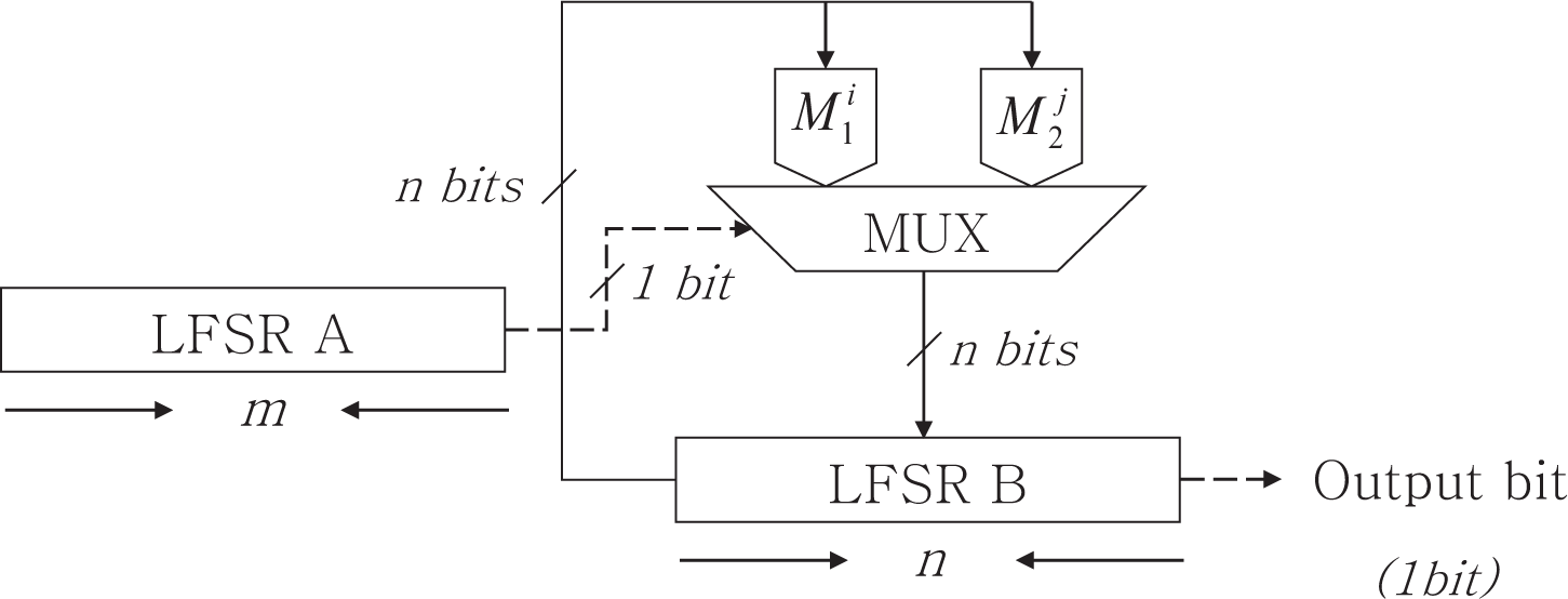
The switching generator, shown in
Figure 1, has two LFSRs
A and
B of length
m and
n, respectively. In
Figure 1, a MUX (multiplexer) is a logic that selects one of several inputs [
29]. The data-generating LFSR
B works as
Equation (11) using two companion matrices
M1 and
M2. These matrices are companion matrices of two primitive polynomials.
The data-generating LFSR B is updated by bits of the controlling LFSR A and two companion matrices M1 and M2. We describe the generating method for output sequences as follows:
Register A is clocked. If the output of A is “0”, then the register B is clocked by using (M1)i, then the output bit is the most significant bit of this register. If the output of A is “1”, then the register B is clocked by using (M2)j, then the output bit is the most significant bit of this register.
|
The period of the output sequences generated by this generator can be up to a maximum (2m − 1) · (2n − 1) if the matrix M2 is applied repetitively in the clocking process.
We define the ordered pair (i, j) of repetition as the switching index. Through using two distinct companion matrices and a carefully chosen switching index in this generator, we can guarantee that this generator can generate the maximum length sequence. For having resistance to the algebraic attack, this switching index is considered as a part of the key. If we choose this index carefully, this generator can be also resistant to the side channel attack.
3.2. Switching Index
The switching index (SI) (i, j) is determined by bits of the controlling register A, where 1 ≤ i ≤ ord(M1) − 1 and 1 ≤ j ≤ ord(M2) − 1. We define the smallest multiplication order of a given matrices M1 and M2 as ord(M1) and ord(M2), when
, where I is the identity matrix. This index can be found through following steps:
In these steps, we call the switching matrix (SM) the multiplications of two companion matrices in Step 2 (a) and the detailed process is shown in Example 1.
Example 1. Let f
c be a characteristic polynomial of degree two for the clock-controlling LFSR and fg1,
fg2 be two distinct polynomials of the same degree three for the data generating LFSR. For each polynomial, companion matrices are as follows: Suppose that an initial state of the clock-controlling LFSR is (0,1); the output sequences are the three-periodic sequences with cycle (0,1,1). Using these sequences, the switching matrix SM is computed as follows: In the case of (
i,
j) = (1, 6),
SM is represented as the below matrix. The characteristic polynomial of this matrix is x3 +
x2 + 1
and is primitive. Therefore, (1, 6)
is the switching index. We can also find other indexes, such as (2, 3), (3, 2), (4, 5), (5, 4)
and (6, 1).
To obtain the switching index for given sizes m and n, we have to compute many operations as follows:
If the size m and n is large, then the time complexity is very high. Therefore, we expressed this situation as a hard problem.
3.3. Application of Switching Generator
To provide strong robustness, stream ciphers generally use many LFSRs or generators based on LFSR. There are two methods for designing stream ciphers: a combination generator and a filter generator [
6]. A5 (GSM) [
30] and E0 (Bluetooth) [
31] were constructed with a combination generator, and Sober (Nessie project) [
32] and Grain eStream project) [
33] were designed with a filter generator. It is not good for security that our generator uses many LFSRs with the controlling LFSR because of the guess-and-determine attacks. We can suggest that a stream cipher use many of our generators to meet a design goal, such as 128-bit security and resistance against side channel attacks and algebraic attacks.
4. The Switching Generator’s Properties
In this section, we present the switching generator’s properties. The generator has resistance to algebraic attacks with maintaining a large period, linear complexity and good randomness.
4.1. Existence of the Switching Index
For given initial states of length
m and
n, the existence proof of the switching index is a hard problem. Therefore, we consider the probabilistic existence of the switching index, where this probability is the chance that the characteristic polynomial of the switching matrix computed by clock control bits and index (
i,
j) is primitive. To compute this probability, we use the following facts:
Let Pr
f,n, shown in
Equation (12), be the probability that a polynomial
f of degree
n in GF(2
n) is primitive. These values for given degrees
n are listed in
Table 1.
From
Equation (12) and the bounds of index (
i,
j), we can compute the expectation Exp
f,i,n of the existence of the switching index for degree
n and a fixed
i as
Equation (13). These expectation values for given degrees
n are listed in
Table 2.
By
Equation (13), we can compute the expectation for degree
n = 3 (see Example 1). The expectation is 3.5. Therefore, there are at least three candidates from a theoretical standpoint. However, there are six candidates, such as (1, 6), (6, 1), (2, 3), (3, 2), (4, 5) and (5, 4), in Example 1.
4.2. Properties of the Switching Index
Since the matrix multiplication is not commutative, switching matrices would be changed depending on the output bits of the clock-controlling LFSR. This property means that the period of the output sequence generated by the switching generator would be changed depending on the initial state for the clock controlling LFSR. However, the below Theorem 1 indicates that the period of the switching generator is constant, independent of the initial state for the clock controlling LFSR [
35].
Theorem 1. For two square matrices M1,
M2,
the characteristic polynomial CP
has a property as follows: Proof. If λ is a root of
, then it is an eigenvalue of
M1 ·
M2. Therefore, there is a non-zero vector
v, such that
M1 ·
M2 ·
v = λ ·
v. We can multiply
M1 ·
M2 ·
v = λ ·
v by
M2 on both sides, then obtain the below equation:
Since M2 · v is non-zero, it is an eigenvector of M2 · M1 with the same eigenvalue that M1 · M2 had. In this case, λ would also be a root of M2 · M1’s characteristic polynomial. Conversely, if λ is a root of
, then it also is a root of M1 · M2’s characteristic polynomial by the same method. Therefore, two characteristic polynomials are the same. □
This theorem means that the characteristic polynomials of a circular multiplication for given matrices are the same. Hence, if the clock-controlling LFSR and switching index is fixed, then the switching generator has the maximum period independent of the initial vector for the clock-controlling LFSR.
4.3. Choice of the Switching Index
There are many candidates for the switching index. If we can choose this index considering the same number of XOR operations on two matrices (
Mi)
i and (
M2)
j, the switching generator has resistance to the side channel attack. By using Example 1, we describe this process of choosing a good switching index. We already found indexes, such as (1, 6), (6, 1), (2, 3), (3, 2), (4, 5) and (5, 4). For each index, we compare the number of XOR operations. The comparison results are listed in
Table 3.
Using the comparison results in this table, we can choose the good switching index as (1, 6) or (6, 1) from six candidates.
4.4. Period and Linear Complexity [36]
By the definition of switching index, the period of the switching generator is (2m − 1) · (2n − 1). The generator’s linear complexity LC is shown in Theorem 2.
Theorem 2. For the given switching generator consisting of two LFSRs of length m and n, if m divides n, then this generator has the linear complexity as follows: Proof. In paper [
37], Chambers
et al. have considered a type of BRM (binary rate multiplier) whose control and generating registers, A and B, are primitive LFSRs of periods 2
m − 1 and 2
n − 1. They have shown that its output sequence has linear complexity
n · (2
m − 1) under two conditions as follows:
every prime factor of 2m − 1 divides 2n − 1.
GCD(αBRM, 2n −1) = 1, where αBRM is the number of clocks applied to Register B after clocking A 2m − 1 times.
This result is able to be applied into a switching generator directly. If
m divides
n, then every prime factor of 2
m − 1 divides 2
n − 1 [
38]. Since the characteristic polynomial of the switching matrix (SM) is a primitive polynomial for a given switching index (
i,
j), the integers
αS.G and 2
n − 1 are relatively prime, where
αS.G is the number of clocks applied to Register B after clocking A 2
m − 1 times for the switching generator. Therefore, the linear complexity of this generator is
n · (2
m − 1).□
Additionally, the minimal polynomial of the output sequence of the switching generator is exactly
. In Example 1, since
, the minimal polynomial of the output sequence is
4.5. Algebraic Properties
At clock t, the internal state Bt of the data-generating LFSR is updated according to the bit information of the clock-controlling LFSR and two companion matrices M1 and M2. This process is represented as Example 2 in detail.
Example 2. We use characteristic polynomials for clock-controlling and data-generating LFSRs, defined in Example 1. Then, the switching index is “(1,6)”, and the switching matrix SM is as follows: Let the initial state of the data generating LFSR be (0,0,1). the internal states Bt are as follows:
We can represent the update process for these internal states as the matrix product of some copies of the matrix M
1 or M
2. The number of copies is defined as exponents. The exponents for each matrix
M1 or
M2 are listed in
Table 4. In this table, we can notice that the exponents are not constant for each bit “0” or “1” of the clock controlling LFSR. This is due to the following mathematical property: for two companion matrix
M1 and
M2 of two distinct primitive polynomials, the matrix M
1 cannot be represented as the matrix product of some copy of the matrix
M2. This explains that the switching generator cannot be implemented as the stop and go generator. Thus, the algebraic attack applied to the stop and go generator cannot be applied to the switching generator.
In Section 3.2, we presented that there are many candidates for the switching index. Additionally, we described that this switching index is considered as a part of the key. This condition is used to guarantee that the switching generator has resistance against the algebraic attack. Even though attackers assume the clock-controlling LFSR, they cannot find the exact switching index among many candidates. Therefore, they cannot construct algebraic equations for the target generator easily.
Attackers have to be able to construct algebraic equations for the target algorithm to attack this algorithm with the basic algebraic attack. If they can attack, then they can apply other advanced algebraic attacks, such as fast algebraic attacks [
13] and higher order algebraic attacks [
39]. However, they cannot construct any algebraic equations in our generator.
4.6. Other Security Evaluation
In clock-controlled generators, the basic idea of guess-and-determine attacks is to guess
m bits of the clock-controlling LFSR state and derive other
n bits through the relationship between the keystream bits and the internal state bits. The time complexity is (2
m − 1) ×
O(
n3), where
O(
n3) is the complexity of the Gaussian elimination method for
n ×
n matrix [
40].
When the keystream bits in the given generator have a significant correlation with the output bits of some LFSRs, we can apply the correlation attacks. Our generator is derived from the alternating step generator. The best time complexity of a correlation attack against the alternating step generator is
O(
n2 × 2
n) [
41]. The switching generator is more robust than the alternating step generator, because attackers cannot know the exact switching index, even though they can know all primitive polynomial for all LFSRs. Therefore, we can argue the complexity for being dominated by the time complexity of the alternating step generator. If we can choose the two parameters
m and
n, such that (2
m − 1) ×
n ≤
n2 × 2
n, namely
n ≤
m ≤
n × (
log2n), then the complexity against these attacks is more than the linear complexity. Therefore, the time complexity against all basic attacks is dominated by the time complexity of the linear complexity.
5. Conclusions
The appearance of fast and efficient block ciphers has caused a diminishing of the importance of stream ciphers due to the convenience of the use of block ciphers in various applications. Therefore, researchers of stream ciphers reviewed some area where stream ciphers would survive: very high speeds in communication links or compact in constrained devices. In the area of constrained devices, LFSRs are used to construct stream ciphers. It has, however, been well known that LFSR-based systems, well suited to low-end hardware implementations, are very vulnerable to algebraic attacks. Furthermore, irregular clock-controlled generators were highly vulnerable against side channel attacks.
In this paper, we proposed a new clock-controlled generator: the switching generator. This generator preserved both the security and efficiency of existing clock-controlled generators. In addition, this system could be resistant to algebraic attacks, because determinate equations for this generator, relating the output bits to the internal state bits for this generator, could not be produced. Especially, we could guarantee the resistance against side channel attacks by choosing a good switching index.
Acknowledgments
This research was supported by the MSIP (Ministry of Science, ICT and Future Planning), Korea, under the ITRC (Information Technology Research Center) support program (NIPA-2014-H0301-14-1004) supervised by the NIPA (National IT Industry Promotion Agency) for Dukjae Moon and Seokhie Hong. Furthermore, this work was supported by the 2014 Research Fund of the University of Seoul for Jaechul Sung.
Author Contributions
All authors have contributed to the study and preparation of the article. The 1st author conceived the idea and wrote the paper. The 2nd author did the security analysis and proved theorems. The 3rd author reviewed and advised for the paper. The corresponding author participated in the security analysis and reviewed for the paper. All authors have read and approved the final manuscript.
Conflicts of Interest
The authors declare no conflict of interest.
References
- Daemen, J.; Rijmen, V. The Design of Rijndael; Springer: Berlin/Heidelberg, Germany, 2001. [Google Scholar]
- Good, T.; Benaissa, M. AES on FPGA : From the Fastest to the Smallest. In Cryptographic Hardware and Embedded Systems—CHES 2005, Proceedings of 7th International Workshop on Cryptographic Hardware and Embedded Systems, Edinburgh, UK, 29 August–1 September 2005; Rao, J.R., Sunar, B., Eds.; Springer: Berlin/Heidelberg, Germany, 2005; 3659, pp. 427–440. [Google Scholar]
- Könighofer, R. A Fast and Cache-Timing Resistant Implementation of the AES. In Topics in Cryptology—CT-RSA 2008, Proceedings of The Cryptograhers’ Track at the RSA Conference 2008, San Francisco, CA, USA, 8–11 April 2008; Malkin, T., Ed.; Springer: Berlin/Heidelberg, Germany, 2008; 4964, pp. 187–202. [Google Scholar]
- Shamir, A. Stream Ciphers: Dead or Alive? Proceedings of ASIACRYPT 2004, Jeju Island, Korea, 5–9 December 2004; Lee, P.J., Ed.; Springer: Berlin/Heidelberg, Germany, 2004; 3329, p. 78. [Google Scholar]
- Ronse, C. Feedback Shift Registers; Lecture Notes in Computer Science; Volume 169, Springer: Berlin/Heidelberg, Germany, 1984. [Google Scholar]
- Menezes, A.J.; van Oorschot, P.C.; Vanstone, S.A. Handbook of Applied Cryptography; CRC Press: Boca Raton, FL, USA, 1996. [Google Scholar]
- David, H.; Bailey, K.L.; Simon, H.D. Using Strassen’s Algorithm to Accelerate the Solution of Linear Systems. J. Supercomput. 1990, 4, 357–371. [Google Scholar]
- Courtois, N.T. The Security of Hidden Field Equations (HFE). In Topics in Cryptology—CT-RSA 2001, Proceedings of The Cryptographers’ Track at RSA Conference, San Francisco, CA, USA, 8–12 April 2001; Naccache, D., Ed.; Springer: Berlin/Heidelberg, Germany, 2001; 2020, pp. 266–281. [Google Scholar]
- Courtois, N.; Pieprzyk, J. Cryptanalysis of Block Ciphers with overdefined Systems of Equations. In Advances in Cryptology—ASIACRYPT 2002, Proceedings of 8th International Conference on the Theory and Application of Cryptology and Information Security, Queenstown, New Zealand, 1–5 December 2002; Zheng, Y., Ed.; Springer: Berlin/Heidelberg, Germany, 2002; 2501, pp. 267–287. [Google Scholar]
- Kipnis, A.; Shamir, A. Cryptanalysis of the HFE Public Key Cryptosystem by Relinearization. In Advances in Cryptology—CRYPTO 1999, Proceedings of 19th Annual International Cryptology Conference, Santa Barbara, CA, USA, 15–19 August 1999; Wiener, M.J., Ed.; Springer: Berlin/Heidelberg, Germany, 1999; 1666, pp. 19–30. [Google Scholar]
- Armknecht, F.; Krause, M. Algebraic Attacks on Combiners with Memory. In Advances in Cryptology—CRYPTO 2003, Proceedings of 23rd Annual International Cryptology Conference, Santa Barbara, CA, USA, 17–21 August 2003; Boneh, D., Ed.; Springer: Berlin/Heidelberg, Germany, 2003; 2729, pp. 162–175. [Google Scholar]
- Courtois, N.T.; Meier, W. Algebraic Attacks on Stream Ciphers with Linear Feedback. In Advances in Cryptology—EUROCRYPT 2003, Proceedings of International Conference on the Theory and Applications of Cryptographic Techniques, Warsaw, Poland, 4–8 May 2003; Biham, E., Ed.; Springer: Berlin/Heidelberg, Germany, 2003; 2656, pp. 345–359. [Google Scholar]
- Courtois, N.T. Fast Algebraic Attacks on Stream Ciphers with Linear Feedback. In Advances in Cryptology—CRYPTO 2003, Proceedings of 23rd Annual International Cryptology Conference, Santa Barbara, CA, USA, 17–21 August 2003; Boneh, D., Ed.; Springer: Berlin/Heidelberg, Germany, 2003; 2729, pp. 176–194. [Google Scholar]
- Lee, D.H.; Kim, J.; Hong, J.; Han, J.W.; Moon, D. Algebraic Attacks on Summation Generators. In Fast Software Encryption—FSE 2004, Proceedings of 11th International Workshop, Delhi, India, 5–7 February 2004; Roy, B.K., Meier, W., Eds.; Springer: Berlin/Heidelberg, Germany, 2004; 3017, pp. 34–48. [Google Scholar]
- Al-Hinai, S.; Batten, L.M.; Colbert, B.D.; Wong, K.K.H. Algebraic Attacks on Clock-Controlled Stream Ciphers. In Information Security and Privacy—ACISP 2006, Proceedings of 11th Australasian Conference, Melbourne, Australia, 3–5 July 2006; Batten, L.M., Safavi-Naini, R., Eds.; Springer: Berlin/Heidelberg, Germany, 2006; 4058, pp. 1–16. [Google Scholar]
- Kanso, A.A. Modified clock-controlled alternating step generators. Comput. Commun. 2009, 32, 787–799. [Google Scholar]
- Hassanzadeh, M.M.; Helleseth, T. Algebraic attack on the More Generalized Clock-Controlled Alternating Step Generator. In. Proceedings of the IEEE 2010 International Conference on Signal Processing and Communications (SPCOM), Bangalore, India, 18–21 July 2010; pp. 1–5.
- Klein, A. Stream Ciphers; Springer: Berlin/Heidelberg, Germany, 2013. [Google Scholar]
- Robshaw, M.J.B.; Billet, O. New Stream Cipher Designs—The eSTREAM Finalists; Springer: Berlin/Heidelberg, Germany, 2008. [Google Scholar]
- Al-Hinai, S.Z.M. Algebraic Attacks on Clock-Controlled Steam Ciphers. Ph.D. Thesis, Doctoral Dissertation, Queensland University of Technology, Queensland, Australia, 2007. [Google Scholar]
- Beth, T.; Piper, F. The Stop-and-Go Generator. In Advances in Cryptology—EUROCRYPT 1984, Proceedings of Workshop on the Theory and Application of Cryptographic Techniques, Paris, France, 9–11 April 1984; Beth, T., Cot, N., Ingemarsson, I., Eds.; Springer: Berlin/Heidelberg, Germany, 1985; 209, pp. 88–92. [Google Scholar]
- Gollmann, D.; Chambers, W.G. Clock-controlled shift registers: A review. IEEE J. Sel. Areas Commun. 1989, 7, 525–533. [Google Scholar]
- Rueppel, R.A. When Shift Registers Clock Themselves. In Advances in Cryptology—EUROCRYPT 1987, Proceedings of Workshop on the Theory and Application of Cryptographic Techniques, Amsterdam, The Netherlands, 13–15 April 1987; Chaum, D., Price, W.L., Eds.; Springer: Berlin/Heidelberg, Germany, 1988; 304, pp. 53–56. [Google Scholar]
- Günther, C.G. Alternating step generators controlled by deBruijn sequences. In Advances in Cryptology—EUROCRYPT 1987, Proceedings of Workshop on the Theory and Application of Cryptographic Techniques, Amsterdam, The Netherlands, 13–15 April 1987; Chaum, D., Price, W.L., Eds.; Springer: Berlin/Heidelberg, Germany, 1988; 304, pp. 5–14. [Google Scholar]
- Chambers, W.G.; Gollmann, D. Lock-in Effect in Cascades of Clock-Controlled Shift-Registers. In Advances in Cryptology—EUROCRYPT 1988, Proceedings of Workshop on the Theory and Application of Cryptographic Techniques, Davos, Switzerland, 25–27 May 1988; Barstow, D., Brauer, W., Brinch Hansen, P., Gries, D., Luckham, D., Moler, C., Pnueli, A., Seegmuller, G., Stoer, J., Wirth, N., Gunther, C.G., Eds.; Springer: Berlin/Heidelberg, Germany, 1988; 330, pp. 331–344. [Google Scholar]
- Coppersmith, D.; Krawczyk, H.; Mansour, Y. The Shrinking Generator. In Advances in Cryptology—CRYPTO 1993, Proceedings of 13th Annual International Cryptology Conference, Santa Barbara, CA, USA, 22–26 August 1993; Stinson, D.R., Ed.; Springer: Berlin/Heidelberg, Germany, 1994; 773, pp. 22–39. [Google Scholar]
- Meier, W.; Staffelbach, O. The Self-Shrinking Generator. In Advances in Cryptology—EUROCRYPT 1994, Proceedings of Workshop on the Theory and Application of Cryptographic Techniques, Perugia, Italy, 9–12 May 1994; Santis, A.D., Ed.; Springer: Berlin/Heidelberg, Germany, 1995; 905, pp. 205–214. [Google Scholar]
- Kanso, A.A. Modified self-shrinking generator. Comput. Electr. Eng. 2010, 36, 993–1001. [Google Scholar]
- Liptak, B. Instrument Engineers’ Handbook: Process Software and Digital Networks; CRC Press: Boca Raton, FL, USA, 2002. [Google Scholar]
- Schneier, B. Applied Cryptography; Wiley: Hoboken, NJ, USA, 1996. [Google Scholar]
- Vainio, J.T. Bluetooth Security; Helsinki University of Techinology: Espoo, Finland, 2000. [Google Scholar]
- Hawkes, P.; Rose, G.G. Primitive Specification and Supporting Documentation for SOBER-t32. Proceedings of the First Open NESSIE (New European Schemes for Signature, Integrity, and Encryption) Workshop, Leuven, Belgium, 13–14 November 2000.
- Hell, M.; Johansson, T.; Meier, W. Grain: A Stream Cipher for Constrained Environments. Int. J. Wirel. Mob. Comput. 2007, 2, 86–93. [Google Scholar]
- Lidl, R.; Niederreiter, H. Introduction to Finite Fields and Their Applications; Cambridge University Press: Cambridge, UK, 1986. [Google Scholar]
- Lay, D.C. Linear Algebra and Its Applications; Addison Wesley: Boston, MA, USA, 2005. [Google Scholar]
- Rueppel, R.A. Analysis and Design of Stream Ciphers; Springer: Berlin/Heidelberg, Germany, 1986. [Google Scholar]
- Chambers, W.G.; Jennings, S.M. Linear Equivalence of Certain BRM Shift Register Sequences. Electr. Lett. 1984, 20, 1018–1019. [Google Scholar]
- Rosen, K.H. Elementary Number Theory and Its Applications; Addison-Wesley: Boston, MA, USA, 2000. [Google Scholar]
- Wang, Q.; Johansson, T.; Kan, H. Some results on fast algebraic attacks and higher-order nonlinearities. Inf. Sec. IET 2012, 6, 41–46. [Google Scholar]
- Atkinson, K. A. An Introduction to Numerical Analysis; Wiley: Hoboken, NJ, USA, 1989. [Google Scholar]
- Khazaei, S.; Fischer, S.; Meier, W. Reduced Complexity Attacks on the Alternating Step Generator. In selected Areas in Cryptography—SAC 2007, Proceeding of 14th International Workshop, Ottawa, Canada, 16–17 August 2007; Adams, C., Miri, A., Wiener, M., Eds.; Springer: Berlin Heidelberg, Germany, 2007; 4876, pp. 1–16. [Google Scholar]
© 2015 by the authors; licensee MDPI, Basel, Switzerland This article is an open access article distributed under the terms and conditions of the Creative Commons Attribution license (http://creativecommons.org/licenses/by/4.0/).


