1. Introduction
Converting heat into electricity is now considered as a way for the recovery of wasted energy in various processes [
1,
2], such as natural gas combustion, oil industry, automobile exhausts, heat treatment furnaces for metal and heat generated by domestic heaters and stoves. Thermoelectric technology represents a significant opportunity for harnessing the available thermal energy. Although thermoelectric devices have been applied since 1940 [
3], for example in laser systems, aerospace vehicles, watches, small portable heaters and sensors [
4,
5], the goal is to get more efficient adaptive devices to new sizes covering many applications for everyday life, not only for industry.
This work has been motivated by the necessity to develop new perspectives for improving these devices. A way to develop new designs is to link them to thermodynamics and heat transfer.
A thermoelectric module (TEM) operates on the basis of the energy transport, entropy and charge carriers in a semiconductor material, which are involved in the Seebeck and Peltier effects [
6]. These effects can be analyzed by the reciprocal relations of Onsager [
7], which express a certain symmetry in the mutual interference of two or more irreversible processes occurring simultaneously in a system (electric conduction and heat conduction are the irreversible processes that appear when an electric field is applied to a TEM) [
7].
The important parameters of the Onsager’s approach are the kinetic coefficients
, that for the particular case of the thermoelectric effects are given by,
where
S is the entropy per carrier,
e is the electron charge,
ρ is the electrical resistance,
κ is the thermal conductivity and
T is the temperature.
The heat and current flows can be written in terms of kinetic coefficients, which are related to thermoelectric properties, such as thermal and electrical conductivity [
7]. From Equations (
1), it is possible to define the thermoelectric coefficients,
One of the most relevant parameters of a thermoelectric system, which combines the coefficients (2) and gives a measure of the efficiency of the TEM, is the thermoelectric figure of merit
Z [
8],
The Seebeck coefficient
α is the generated voltage per unit of temperature. This coefficient is a main property of the material, and it is related to the carrier charge transport. It should be noted that
α is directly proportional to the entropy transported by the flux of carriers
S, which is given by the following relationship,
Diverse strategies have been developed for improving the figure of merit through optimization of the materials and the thermoelectric devices [
9,
10,
11,
12,
13]. One of them is the combination of segments of different materials to form the legs of a thermocouple, but with the condition that these materials satisfy the criterion of compatibility, proposed by Snyder [
14,
15]. This approach combines a thermodynamic analysis with the study of thermoelectric properties (
α,
ρ,
κ). In this approach, the main quantity is the compatibility factor
s,
where
Z is the figure of merit,
T is the average temperature and
α is the Seebeck coefficient.
According to the information mentioned above, it is important to analyze the impact of the Seebeck coefficient on the system’s performance to understand the behavior of a thermoelectric system under different configurations. On the physics of the Seebeck coefficient, we briefly mention that when a metal is submitted to a temperature difference,
, in the ends with (
), there exists a net diffusion of electrons from the hot end towards the cold end, due to the energetic difference between electrons in the hot end at
and the cold end at
. This fact leaves behind exposed positive metal ions in the hot region and accumulates electrons in the cold region. This situation prevails until the electric field development between the positive ions in the hot region and the excess electrons in the cold region prevents further electron motion from the hot to cold side [
16]. A voltage
is therefore developed between the hot and cold ends with the hot end at the positive potential. Both quantities
and
are related by the next equation,
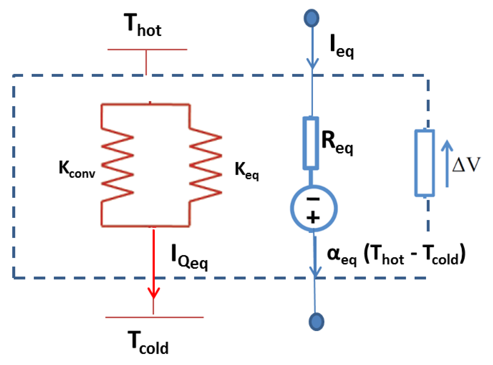
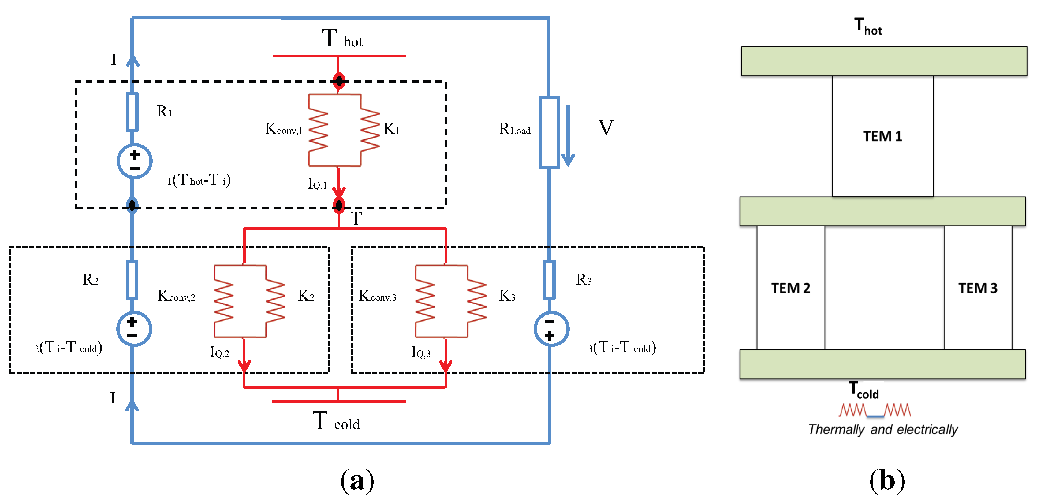
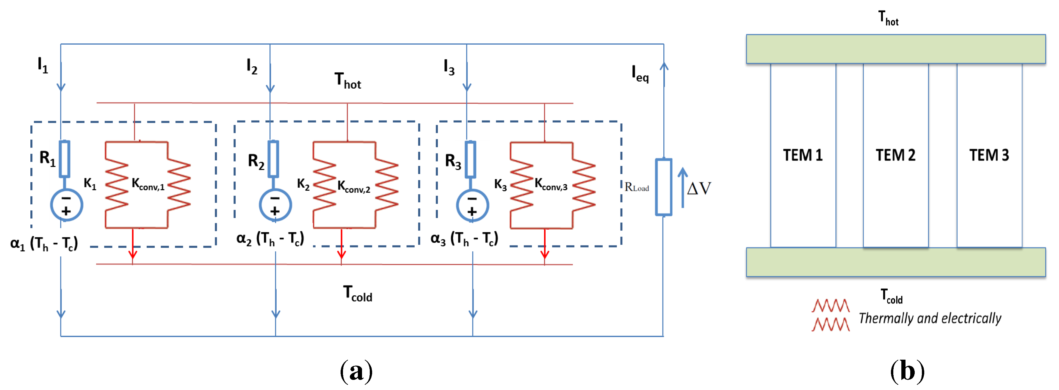
In this work, we consider a thermoelectric system composed of conventional and segmented TEMs connected in different ways. To achieve this goal, we use the new approach proposed by Goupil and Apertet [
17,
18], in which a thermoelectric module is considered as an equivalent thermal-electrical circuit (see
Figure 1). Following these methods, we derive the figure of merit of these systems.
In the following sections, we show the obtained results by applying this new approach.
Figure 1.
Thermoelectric generator and its representation as a thermal-electrical circuit.
Figure 1.
Thermoelectric generator and its representation as a thermal-electrical circuit.
3. Arrangements for Thermoelectric Materials in TEGS
We study the role of the thermoelectric properties in the CTEG. Firstly, we consider the configuration effect, and secondly, we study the role of the thermoelectric properties in the composite CTEG.
3.1. Case I: Homogeneous Thermoelectric Properties, Configuration Effect
In this case, we consider each configuration of the TEMs with the same thermoelectric material, ;
Homogeneous TEP TEGS:
where
i = (BiTe, PbTe or SiGe).
3.2. Case II: Heterogeneous Thermoelectric Properties, Arrangements of Thermoelectric Materials
For this case, we consider the three configurations described above, but with two equal materials and the other one different. Thus, two TEMs have the same semiconductor material and the other one a different semiconductor material.
4. Results and Discussion
Now, we show our results for the two cases mentioned above: the first is analyzed by applying Equations (
10)–(
12) matching the three modules to the same material; the second case is studied by applying Equations (
13)–(
15) using different arrangements of thermoelectric material when
;
;
where
can be any of the thermoelectric materials (BiTe, PbTe, SiGe).
4.1. Homogeneous TEGS: Effect of the Configuration
In this first case, we are interested in the effect of the configuration of the CTEG on the equivalent figure of merit,
. We consider the case when the three TEMs have the same thermoelectric material,
i.e.,
or, equivalently,
.
Table 1 shows our numerical values obtained for the equivalent figure of merit
of the considered configurations.
Table 1.
Numerical values of , for each of the three configurations using different materials.
Table 1.
Numerical values of , for each of the three configurations using different materials.
| Material | | | |
|---|
| BiTe | 0.00212133 | 0.00305269 | 0.00195898 |
| PbTe | 0.00055109 | 0.000657238 | 0.000586714 |
| SiGe | 0.000287562 | 0.00033337 | 0.000314212 |
Notice that different values of the figure of merit for each configuration are obtained when the three thermoelectric modules are made with the same thermoelectric material, i.e., . The highest value of in each configuration is reached when we use BiTe; the most efficient configuration corresponds to when the TEMs are connected thermally and electrically in parallel , while the least efficient configuration corresponds when we use SiGe as the thermoelectric material and the TEMs is connected electrically and thermally in series.
4.2. Heterogeneous TEGS: Different Arrangements of Thermoelectric Materials
In this section, we analyze the effect of thermoelectric materials arrangements on the equivalent figure of merit,
, for each configuration. For this case, we consider that
,
i.e., two TEMs are made of the same thermoelectric material and the third
is made of a different thermoelectric material. Thus, we have three possibilities (
,
,
) for each configuration. Notice that each arrangement has six different combinations if the cyclical order of the material is taken into account. Thus, for each system, SC, PSC and TEP, we have eighteen possible combinations.
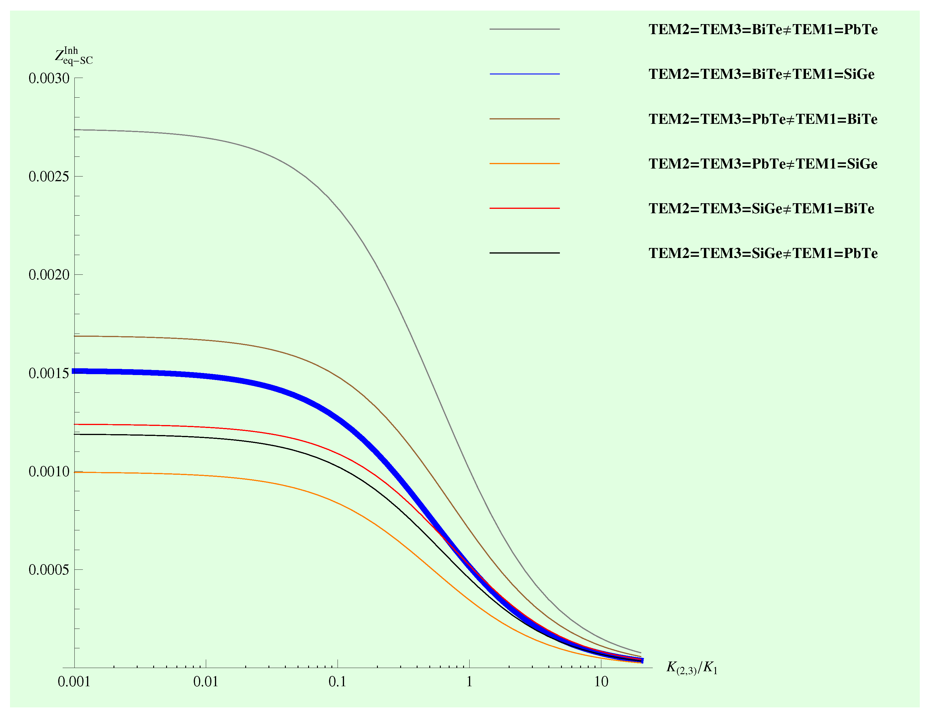
Figure 5,
Figure 6 and
Figure 7 show the behavior of
in terms of the intrinsic thermal conductances ratio
for the optimal cases of each configuration, and
Table 2,
Table 3 and
Table 4 show the maximum values of the figure of merit
, respectively.
From
Table 2,
Table 3 and
Table 4, it must be noted that for each of the three configurations of the CTEG, there are most efficient material arrangements in each configuration when
.
Table 5 shows each configuration with the most efficient material arrangements for each TEM.
Figure 5.
The equivalent figure of merit corresponding to heterogeneous SC CTEG, under the condition . The highest numerical value corresponding to .
Figure 5.
The equivalent figure of merit corresponding to heterogeneous SC CTEG, under the condition . The highest numerical value corresponding to .
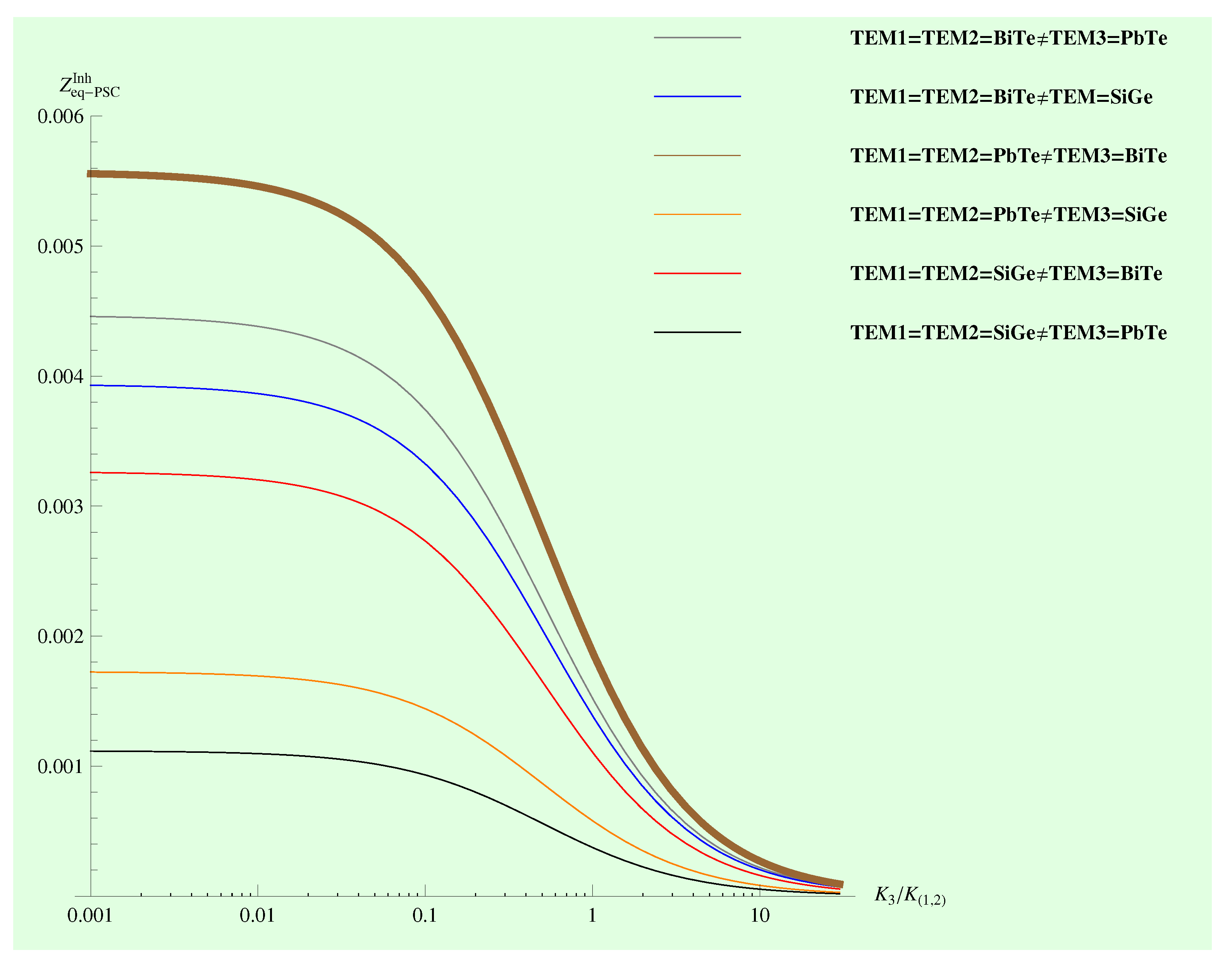
Figure 6.
The equivalent figure of merit corresponding to heterogeneous PSC TEGS under the condition . The highest numerical value corresponding to .
Figure 6.
The equivalent figure of merit corresponding to heterogeneous PSC TEGS under the condition . The highest numerical value corresponding to .
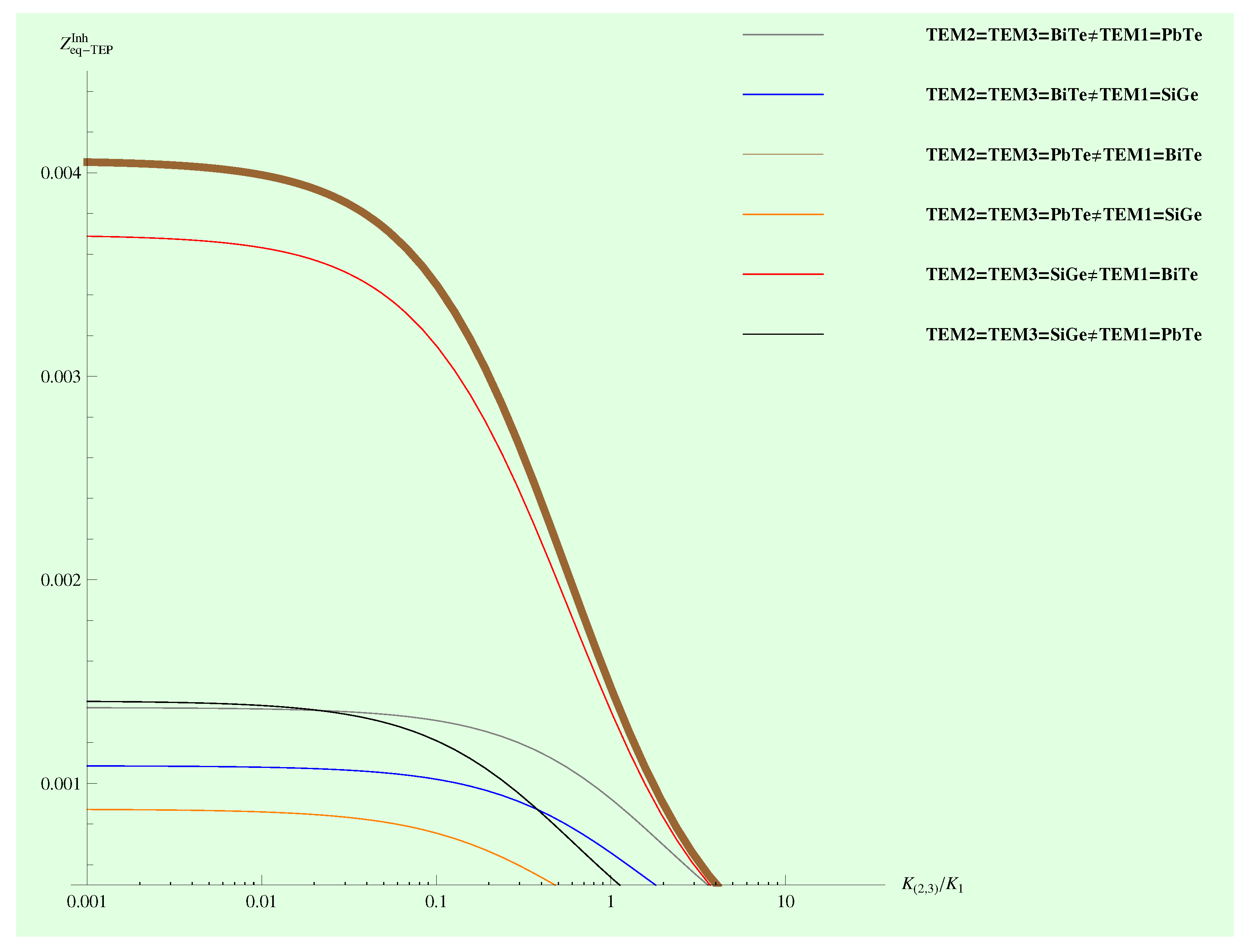
Figure 7.
The equivalent figure of merit corresponding to the TEP TEGS under the condition . The highest numerical value corresponding to .
Figure 7.
The equivalent figure of merit corresponding to the TEP TEGS under the condition . The highest numerical value corresponding to .
Table 2.
Numerical values of for SC TEGS with the arrangement .
Table 2.
Numerical values of for SC TEGS with the arrangement .
| | |
|---|
| BiTe | PbTe | 0.00168734 |
| SiGe | 0.0012388 |
| PbTe | BiTe | 0.00273649 |
| SiGe | 0.00118802 |
| SiGe | BiTe | 0.00150947 |
| PbTe | 0.000994534 |
Table 3.
Numerical values of for PSC TEGS with the arrangement .
Table 3.
Numerical values of for PSC TEGS with the arrangement .
| | |
|---|
| BiTe | PbTe | 0.0055567 |
| SiGe | 0.00325841 |
| PbTe | BiTe | 0.00445846 |
| SiGe | 0.0011157 |
| SiGe | BiTe | 0.00392902 |
| PbTe | 0.00172358 |
Table 4.
Numerical values of from the TEP arrangement under condition .
Table 4.
Numerical values of from the TEP arrangement under condition .
| | |
|---|
| BiTe | PbTe | 0.00405227 |
| SiGe | 0.00108556 |
| PbTe | BiTe | 0.00137141 |
| SiGe | 0.000871679 |
| SiGe | BiTe | 0.00368808 |
| PbTe | 0.00140252 |
Table 5.
Most efficient arrangements in each case .
Table 5.
Most efficient arrangements in each case .
| |
|---|
| SC | |
| PSC | |
| TEP | |
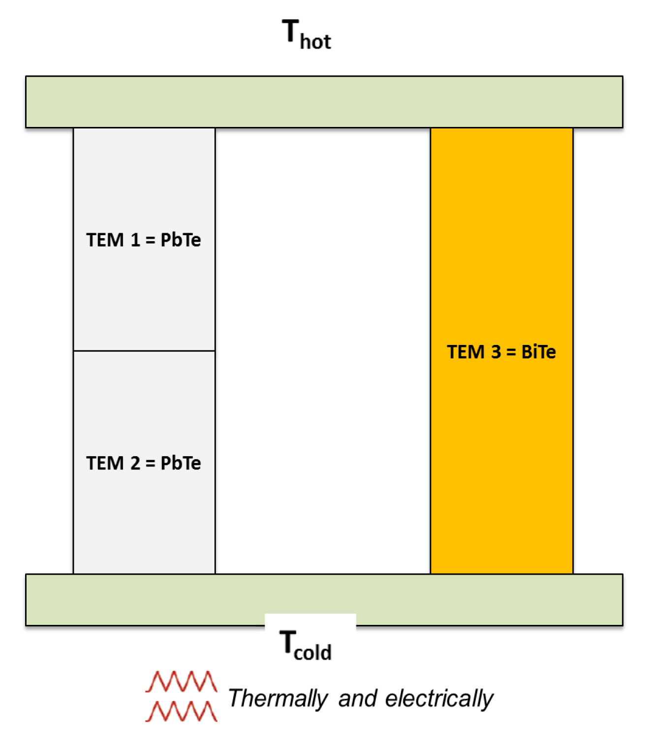
Our results also show that the most efficient system of the three configurations is the PSC configuration with the corresponding material arrangement, namely
; see
Figure 8.
Figure 8.
The optimal configuration corresponds to the PSC TEGS under the condition .
Figure 8.
The optimal configuration corresponds to the PSC TEGS under the condition .
Furthermore, notice the effect of the position of the thermoelectric material in the CTEG through the TEMs on the equivalent thermoelectric figure of merit of the system. It suggests that the CTEG works more efficiently depending on the position of a thermoelectric material in conjunction with other materials.
4.3. Maximum Power and Efficiency
The performance of a TEG is characterized by its thermal efficiency, such as a heat engine, and the generated electric power (from the point of view of energy conversion); both of them are functions of the figure of merit. In this section, we analyze the generated maximum power and the efficiency of the PSC system. We assumed that the maximum value of can be reached.
4.3.1. Maximum Power
For the ideal model of a TEM, which does not take into account the effect of the heat sinks, the maximum electrical power delivered to the load is given by,
However, when a TEM has coupled heat exchangers, it is necessary to consider a thermal contact conductance,
. We calculate the electrical power produced by the PSC system taking into account the thermal contact conductance and thermal conductance at zero electrical current. Thus, the maximum output power, using the corresponding maximum value of the equivalent figure of merit
, is given by [
20],
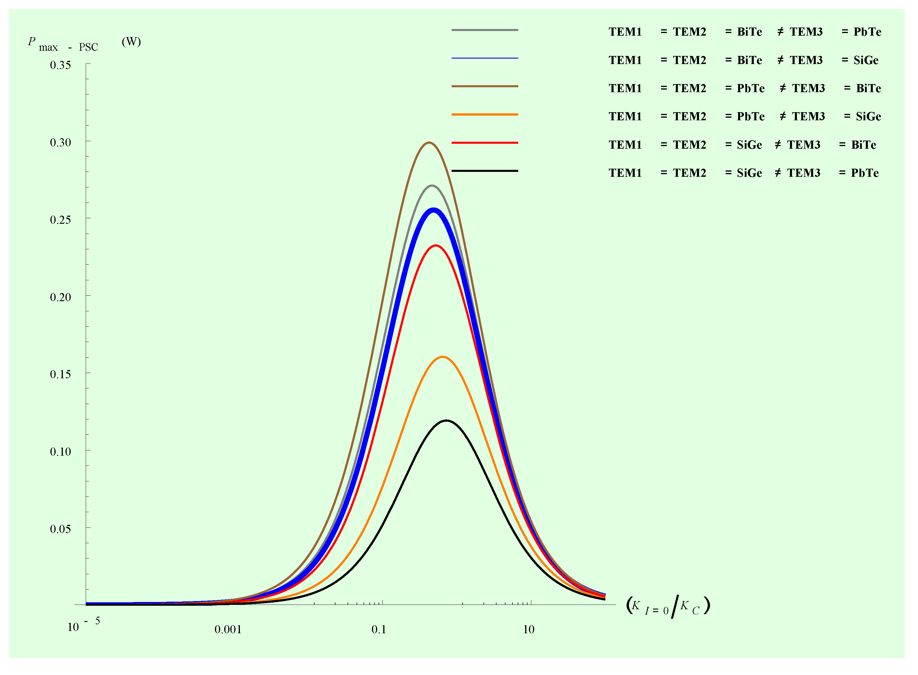
Figure 9 shows maximum power values for the PSC system as a function of the ratio
,
i.e., in terms of internal thermal conductance
and the contact thermal conductance
, with the condition
.
Figure 9.
Maximum power of the system PSC under the condition , the highest numerical value corresponding to case .
Figure 9.
Maximum power of the system PSC under the condition , the highest numerical value corresponding to case .
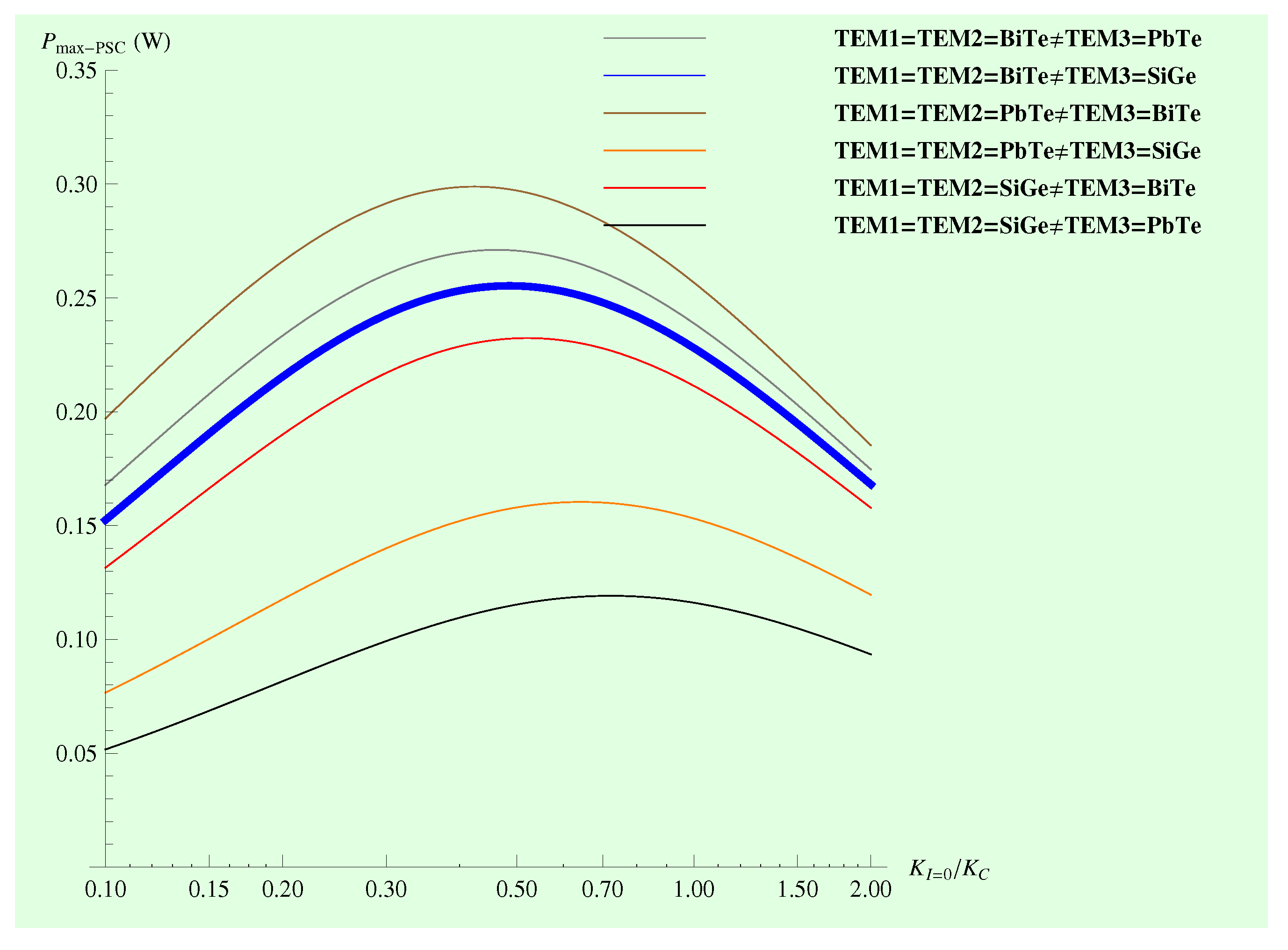
Figure 10 shows clearly the interval of values for the ratio
, where the maximum output power reaches its maximum values.
Figure 10.
The output power of the system PSC reaches the maximum values.
Figure 10.
The output power of the system PSC reaches the maximum values.
We note from
Figure 10 that each of the material arrangements has a characteristic value of
in which the electrical power reaches maximum values. For example, when
, the maximum value for the electrical power is between
and
. In fact, the PSC system reaches the maximum value of the electrical power at small values of the ratio
, compared to other systems, e.g.,
, which reaches maximum values between
and
.
4.3.2. Efficiency
The efficiency of a thermoelectric generator as a function of
Z is given by,
For the PSC system with the
arrangement, we replace
Z by
,
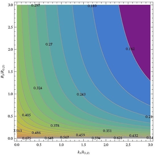
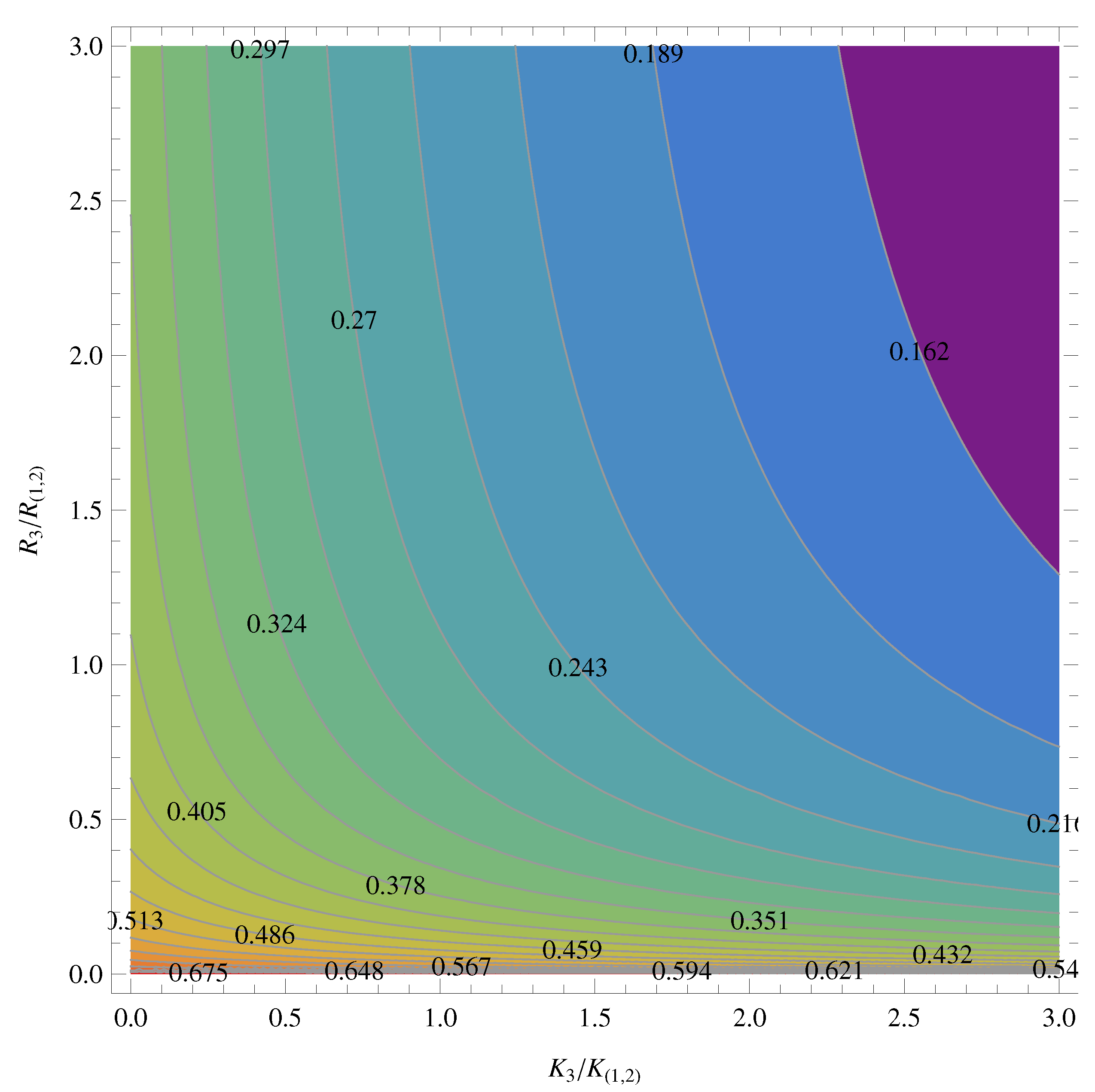
Finally, for an ideal TEG, i.e., without taking into account the heat exchangers, we can analyze the performance of the TEG considering (1) the intrinsic thermal conductances ratio () and (2) the electrical resistances ratio ().
Figure 11 shows a contour plot for different values of
as a function of the ratios,
and
.
Figure 11.
Contour plot: efficiency for the PSC-system assuming the condition , assuming the maximum value of ().
Figure 11.
Contour plot: efficiency for the PSC-system assuming the condition , assuming the maximum value of ().
In
Figure 11, we can observe that the range of optimal values for the best performance of a PSC composite TEG is between
and
for
and
, respectively. It is remarkable that the thermal conductances ratio shows a wider range of good values in comparison with the electrical resistances ratio, which shows a more restricted range.
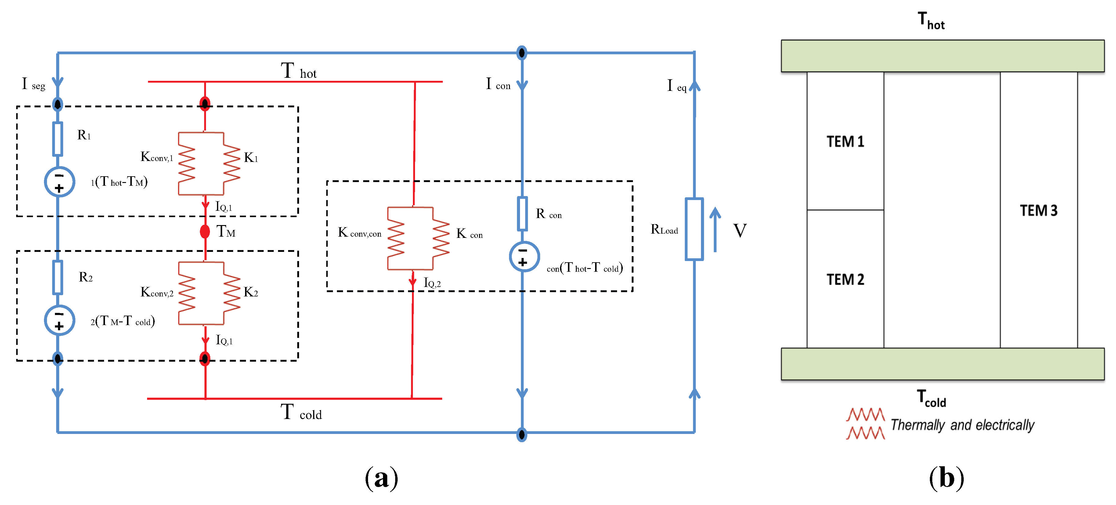
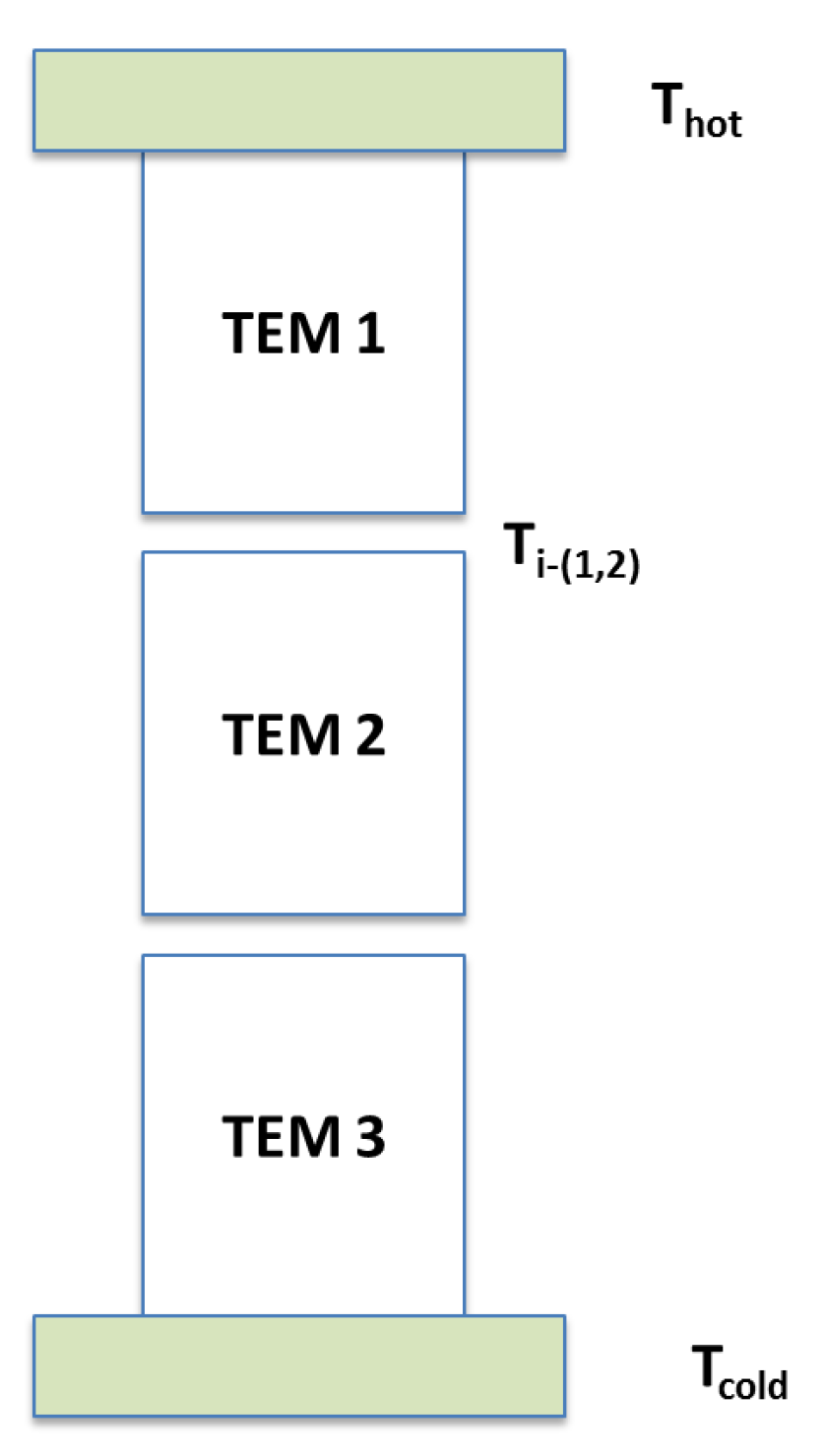
5. The Case of a Three-TEM Chain Thermally and Electrically Connected in Series
Finally, we consider a three-TEMs chain, which is a basic connection between thermoelectric elements that are thermally and electrically connected in series. This model corresponds to segmented branches in TEMs. Recently, an equivalent model of two thermoelectric generators in series has been studied [
21]. However, the combination of more than two materials for segmented branches is used for different ranges of temperature.
Applying the recently-proposed approach [
21] for the system shown in
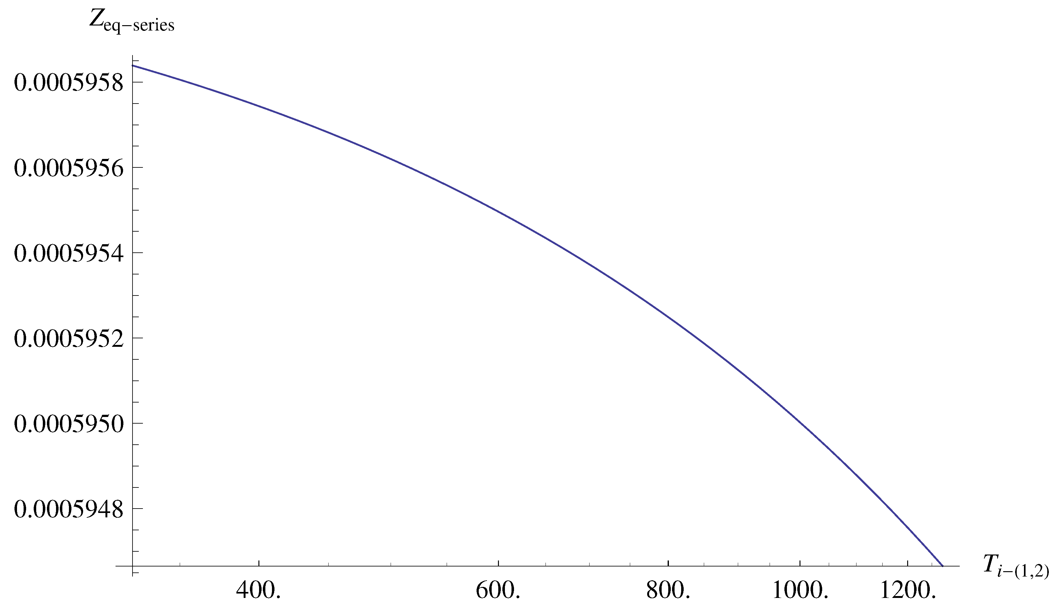
Figure 12, the equivalent thermoelectric figure of merit is given by,
where
is the intermediate temperature between the
and
. In Equation (
20), we have expressed
in terms of
and
, but we have no analytical expression for
temperature. Thus, this case need major revision in future work. However, now, we show the variation of
as a function of
using three different materials, namely
,
and
.
Figure 13 shows the variation of
as a function of
.
Figure 12.
Three-TEM chain thermally and electrically connected in series.
Figure 12.
Three-TEM chain thermally and electrically connected in series.
Notice that the values of are in the range from 373 K to 1273 K. For this range of temperatures, we have an approximate value of . If the system were composed of more than three TEMs, as can be inferred, the case is more complex. In this case, we would have a set of unknowns -, (being m, n) each couple of TEMs in the chain. Comparing the value of of this three-TEM chain with the values of corresponding to -, we clearly confirm that these systems reach a higher value of .
Figure 13.
Equivalent figure of merit for the series-system as a function of , assuming three different materials.
Figure 13.
Equivalent figure of merit for the series-system as a function of , assuming three different materials.
7. Conclusions
In this work, we have studied the role of the thermoelectric properties on the equivalent thermoelectric figure of merit of a composed thermoelectric system. It has been shown that there are two conditions that affect the performance of a thermoelectric system: (1) the thermal and electrical connection between TEMs; and (2) the arrangement (cyclic order) of thermoelectric materials. In fact, the of the CTEG composed of three TEMs shows different maximum values using the same thermoelectric material for each TEM, i.e., , but under different configurations, i.e., under different thermal and electrical connections. For example, we found that for the case of the BiTe material, a higher value of is obtained for the configuration PSC compared to the SC and TEP configurations.
Furthermore, have different maximum values, when we use two different materials for the TEMs, i.e., under the condition . In this case, we found that the PSC-configuration is the most efficient configuration followed by the TEP and SC configurations, respectively. Furthermore, we found that the PSC-configuration, using BiTe and PbTe for the TEMs, reaches low values when and , but the optimal performance is obtained with the arrangement ).
For completeness, we have shown the effect of contact thermal conductance on the for the more efficient case, PSC-CTEG system, in terms of both the ratio (intrinsic thermal conductances) and (intrinsic electrical resistance).
The arrangements proposed in this work have the advantage that they can achieve a higher figure of merit value compared to a conventional thermoelectric module, in particular the PSC-CTEG system. We have shown that a thermal connection in series of two modules improves the performance when they are thermally connected in parallel with a third TEM, resulting in a higher value of Z.
These results are useful for the design of new thermoelectric systems with the optimal combination of materials to form the legs of the thermocouples in multistage thermoelectric systems, each stage with different material. Thus, our analysis shows elements of validation, which allows one to select: (1) the best thermal and electrical connection; (2) the best materials; and (3) the corresponding position in the arrangement. For future work, we consider it very important to include geometric factors and other extrinsic factors, such as the electrical contact resistance, for more realistic results. Additional later work is required to generalize our results for a system of N modules.


