1. Introduction
Carbon dioxide (CO
2), which is a natural working fluid, has been considered a promising alternative to synthetic refrigerants owing to its virtues such as lack of toxicity, no flammability, low cost, admirable thermal physical properties and absence of hazards to the environment. Nevertheless, the critical temperature of CO
2 is generally lower than the typical heat rejection temperature values of air-conditioning systems, so the transcritical CO
2 refrigeration cycle is applicable [
1]. However, the conventional throttle valve CO
2 systems exhibit low energy efficiency due to the large throttling losses caused by the high pressure difference during the expansion.
To overcome the foregoing problems, several devices, such as an expander, internal heat exchanger, two-stage compressor and two-phase ejector, have been proposed. The employment of an expander to replace the throttle valve is expected to give the largest improvement of the cycle efficiency. This action would not only increase the cooling effect of the evaporator but also can reduce the net compression work. Through parametric analysis, Robinson and Groll [
2] [
2]showed that the cycle COP improvement could reach about 25% when an expander with an isentropic efficiency of 60% is used. Yang
et al. [
3] found that the COP and exergy efficiency of the cycle increases by 33% and 30%, respectively, owing to the substitution of the expander for throttling valve. Sarkar [
4] showed that the replacement of the throttling valve with an expander of 80% isentropic efficiency resulted in a COP increase of 18% and an optimum heat rejection pressure decrease of 2.5%. Nickl
et al. [
5] found that the integration of three-stage expander in the CO
2 refrigeration system with two-stage compression and intercooling can gain at least 40% COP improvement. Baek
et al. [
6] developed a reciprocating piston expander prototype and found that the device provided a 3.5% to 5.7% cooling capacity increase and a 7% to 10.5% COP improvement. Kim
et al. [
7] investigated the performance of a scroll expressor (expander-compressor) by numerical simulation and found that the machine provided an increase of 8.6% in the cooling capacity and a COP improvement of 23.5% for the cycle. Jia
et al. [
8] developed a double acting rotary vane expander prototype and found that a maximum COP improvement of 27.2% was obtained compared with the throttling valve cycle. Li
et al. [
9] developed a rolling-piston expander prototype and found that it can improve the cycle COP by at least 10%.
For conventional CO
2 systems with isenthalpic throttle valves, an IHE that is often employed to improve the cycle performance is considered as an essential component. Boewe
et al. [
10] found that the addition of IHE in the basic CO
2 cycle can bring the cycle COP improvement by 25%. Sarkar
et al. [
11] found that the cycle with IHE provided a 15% increase in cycle COP and a 13% decrease in optimum heat rejection pressure compared to those of the basic transcritical cycle at an evaporator temperature of 0 °C and gas cooler outlet temperature of 60 °C. Cho
et al. [
12] found that the cooling capacity and COP can be improved by 6.2%–11.9% and 7.1%–9.1% respectively owing to the IHE addition in the transcritical CO
2 cycle. Through the experimental study, Aprea and Maiorino [
13] discovered that the use of IHE can increase COP by 10% in the residential application. Torrella
et al. [
14] experimentally found that the IHE addition in transcritical CO
2 refrigeration system provides a maximum increase in cooling capacity of 12%, an increase of the cycle COP of up to 12% and a maximum increase of the discharge temperature of 10 °C at −15 °C evaporating temperature. Through experimental and theoretical studies, Rigola
et al. [
15] found that the IHE addition increases cycle COP by about 20% at a gas cooler outlet temperature of 35 °C. Zhang
et al. [
16] found that the COP is slightly decreased by an IHE in a CO
2 subcritical refrigeration cycle.
It can be seen that the published papers about the effect of IHE on performance of CO
2 refrigeration cycle are limited to the conventional expansion valve system. Significantly less literature is available on the topic of the applicability of IHE in the transcritical CO
2 refrigeration system with an expander. To the best knowledge of the authors, Wang [
17] performed thermodynamic analysis on the two stage transcritical CO
2 expander refrigeration cycle with IHE and reported a 1.2% decrease in COP over the cycle without IHE where the expander isentropic efficiency was assumed to be constant 0.5. Robinson and Groll [
2] revealed that an IHE addition in the transcritical CO
2 refrigeration cycle with an expander tends to reduce the cycle COP by up to 8% where the expander isentropic efficiency was assumed to be 0.6. However, the effect of IHE on the performance of the cycle with various expander isentropic efficiencies was not investigated in the two literatures.
In this paper, the effect of IHE in the transcritical CO2 refrigeration cycle with an expander under typical air-conditioning operating conditions is investigated. The variation of the expander isentropic efficiency is taken into account. The analysis of the cycle performance has been done based on the first and second laws of thermodynamics.
3. Thermodynamic Modeling
The entire system has been modeled based on the energy balance of the individual components of the system. Steady flow energy equations based on the laws of thermodynamics have been employed in each case. The main assumptions of the analysis are as follows:
There are no pressure losses in pipes and heat exchangers.
The exiting working fluid of the evaporator is saturated vapor.
The compression process and the expansion process are adiabatic but non-isentropic.
The isentropic efficiency of the expander has a given value and is not affected by its operating conditions.
The work output of the expander is used to offset the power required by the compressor [
3,
18].
3.1. Energy Analysis
The refrigerating effect of the evaporator is:
The work input to the compressor for the process 1–2 is calculated as:
The isentropic efficiency of the compressor is defined as:
η
com is calculated from the following expression [
19]:
The heating effect of the gas cooler is:
The output work for the expansion process 3–4 is given by:
The isentropic efficiency of the expander is defined as:
The energy balance equation in IHE can be expressed as:
The effectiveness of IHE is defined as:
The COP of the refrigeration cycle can be calculated as:
3.2. Exergy Analysis
The specific exergy of the refrigerant can be evaluated as:
For Q at constant temperature T, the heat exergy rate exQ can also be calculated by:
Exergy loss equations for the compressor, gas cooler, IHE, expander/throttle valve, and evaporator are given as follows:
For the compressor:
For the gas cooler:
For IHE:
For the expander:
For the throttle valve:
For the evaporator:
Therefore, the total exergy losses of the system are:
The exergy efficiency of the refrigeration cycle with an expander can be expressed as:
Based on the above analysis, the simulation program was developed to evaluate the effect of IHE in the transcritical CO
2 refrigeration cycle with an expander. The carbon dioxide property data were obtained from REFPROP [
20].
4. Results and Discussion
In this study, two IHE efficiencies are considered during the simulation, i.e., 0.6 and 0.8. In the following diagrams, “Expander” denotes the expander refrigeration cycle, “Expander IHE” denotes the expander refrigeration cycle with an IHE, “Valve” denotes the conventional throttling valve refrigeration cycle, “Valve IHE” denotes the conventional throttling valve refrigeration cycle with an IHE.
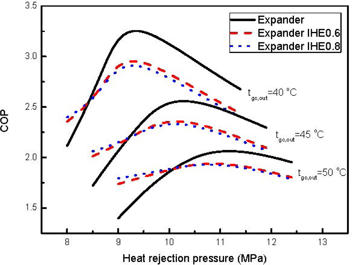
The COP variations of the investigated systems with heat rejection pressure for different gas cooler outlet temperatures at an evaporating temperature of 5 °C and expander isentropic efficiency of 0.8 are depicted in
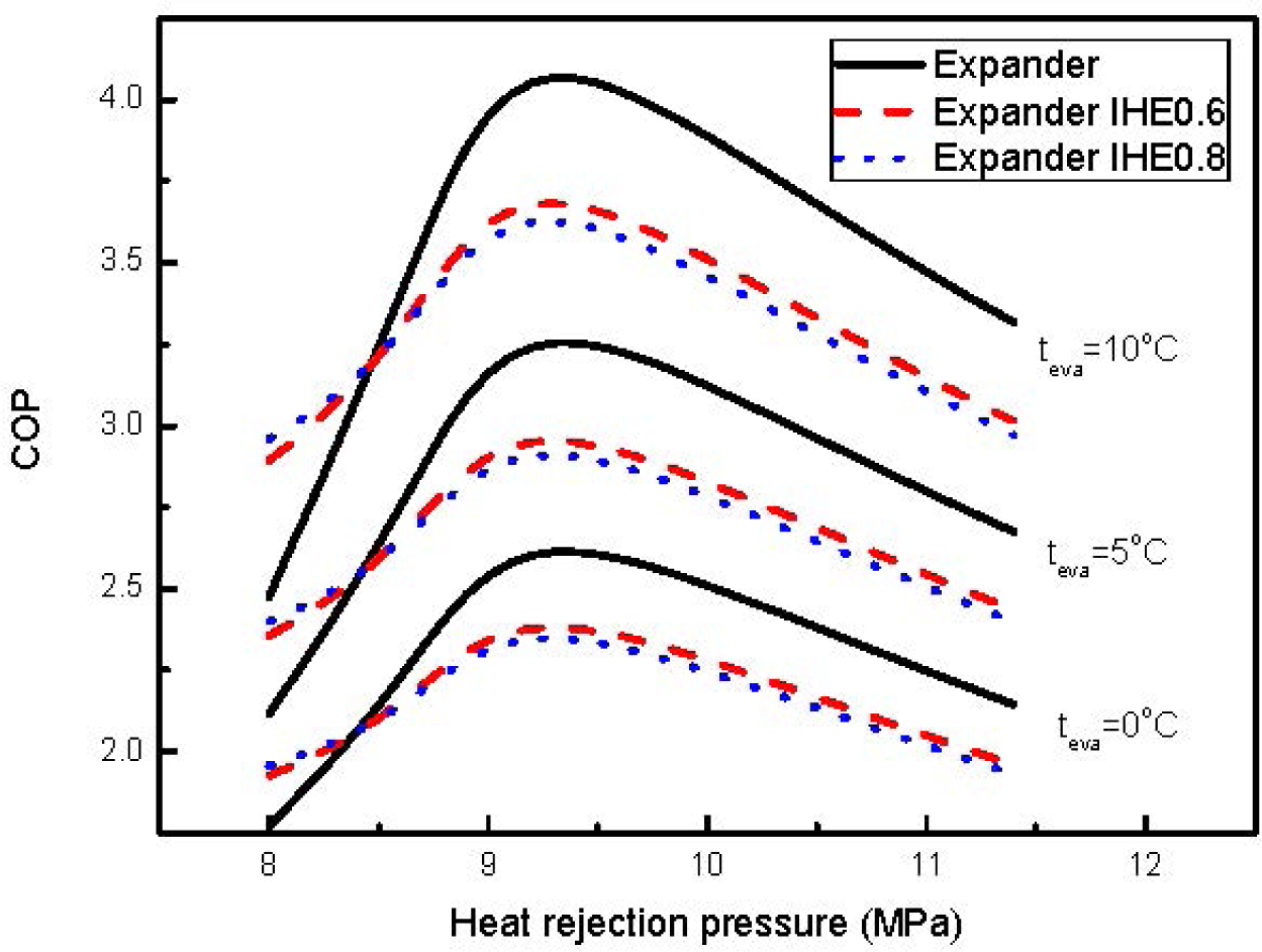
Figure 2. The COP variations of the investigated systems with heat rejection pressure for various evaporating temperatures at a gas cooler outlet temperature of 40 °C and expander isentropic efficiency of 0.8 are presented in
Figure 3. Like the conventional system with an isenthalpic expansion valve, COP first increases until a point and then decreases. The pressure where COP reaches the maximum value is called the optimum heat rejection pressure. It is observed that the optimum heat rejection pressure is almost independent of the evaporating temperature, but it shifts to higher values with increase in gas cooler outlet temperature. As the gas cooler outlet temperature decreases or the evaporating temperature increases, the COP values of the investigated cycles increase.
Nevertheless, unlike what has been observed in conventional cycles with isenthalpic expansion valves, the IHE addition in the cycle with an expander is usually not beneficial. The cycle with IHE is only favorable at lower heat rejection pressures compared with the cycle without IHE. The maximum COP values of the cycle with an expander decrease after IHE is used. This inclination is consistent with the published literatures [
2,
17]. The decline of the maximum COP increases for more efficient IHE. But this case changes for the better as the gas cooler exit temperature increases. In the cases of the effectiveness of IHE being 0.8 and the evaporating temperature being 5 °C, the cycle COP decrease percent by IHE addition is 10.5%, 8.9%,and 6.5% at the gas cooler outlet temperature of 40 °C, 45 °C and 50 °C respectively. In the cases of the effectiveness of IHE being 0.8 and the gas cooler outlet temperature being 40 °C, the cycle COP decrease percentage achieved by IHE addition is 10.2%, 10.5%,and 10.8% at the evaporating temperature of 0 °C, 5 °C and 10 °C respectively. It is also noticed that the optimum heat rejection pressure of the cycle with IHE is lower than that of the cycle without IHE under various operating conditions.
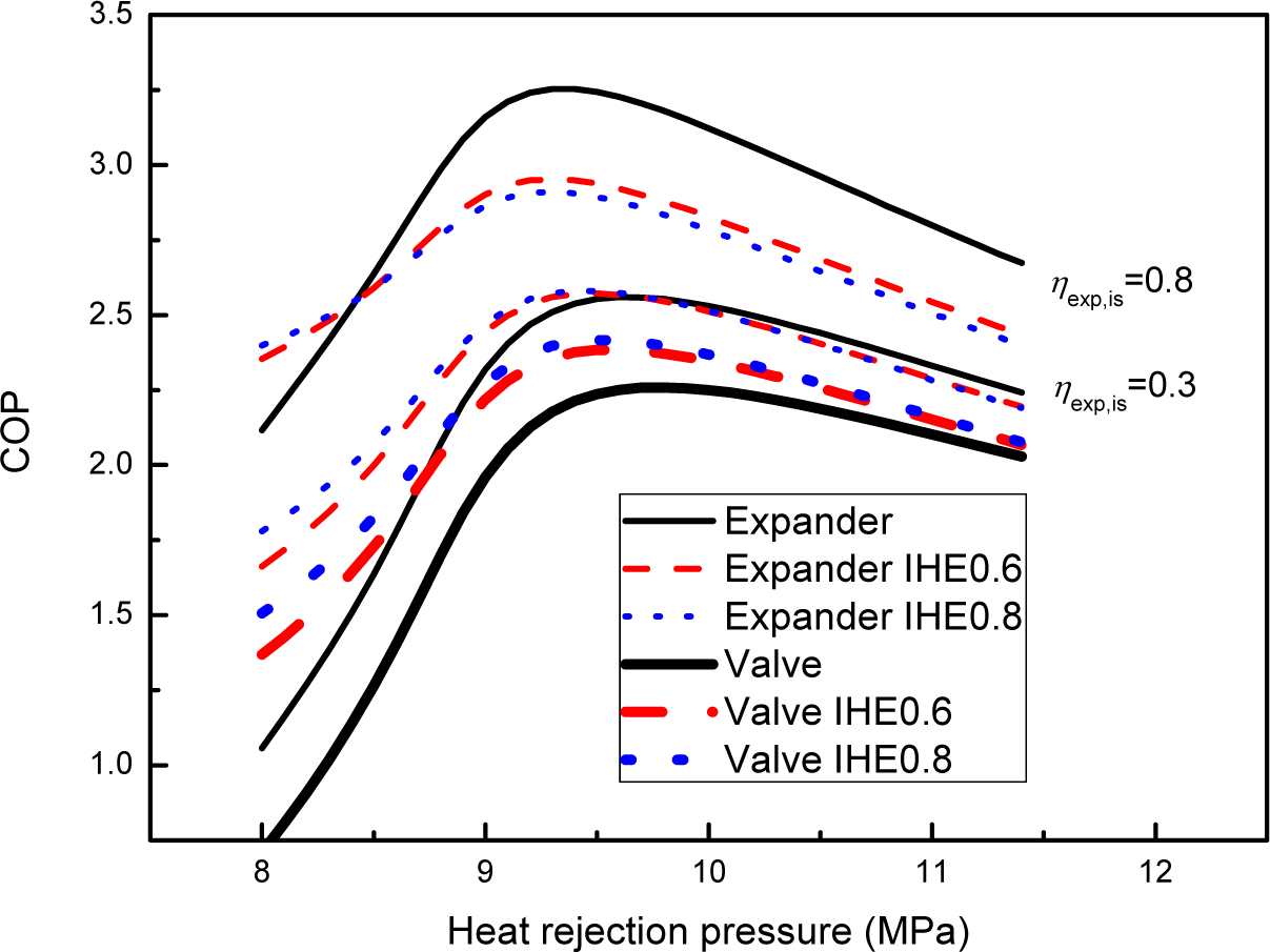
Figure 4 depicts the COP variations of the investigated cycles with the heat rejection pressures at different expander isentropic efficiencies under the condition that the gas cooler outlet temperature and the evaporating temperature are 40 °C and 5 °C respectively. Three cases are considered,
i.e., the throttle valve refrigeration cycle, the expander cycle with η
exp,is = 0.3 and the expander cycle with η
exp,is = 0.8. It can be seen from
Figure 5 that the optimum heat rejection pressure of the cycle with IHE is lower than that of the cycle without IHE under various expander isentropic efficiencies. Furthermore, the expander cycles with and without IHE outperform the conventional throttle valve cycles in the range of the heat rejection pressures used in this study, but the improvement degree in COP is very sensitive to the isentropic efficiency of the expander. When the isentropic efficiency of the expander is 0.8, the maximum COP of the expander cycle without IHE is 44.0% higher than the maximum COP of the conventional throttle valve cycle without IHE. The maximum COP of the expander cycle with IHE is 20.4% higher than the maximum COP of the conventional cycle with IHE. Nevertheless, those two figures will lower to 13.3% and 6.8% respectively when the isentropic efficiency of the expander is 0.3. For the throttle valve refrigeration cycle, the cycle COP can be increased by the IHE addition at any heat rejection pressure. The more efficient the IHE, the higher the system COP. This inclination of the throttle valve cycle is consistent with the published literatures [
10–
15]. The similar trend is observed for the expander cycle with η
exp,is = 0.3. But as already mentioned earlier, it is not this for the expander cycle with η
exp,is = 0.8, in which the use of IHE makes the system COP decrease generally. In the case of the effectiveness of IHE being 0.8, the use of IHE increases the maximum COP by about 6.9% for the throttle valve cycle, the addition of IHE yields roughly 0.9% improvement in maximum COP for the expander cycle when the expander isentropic efficiency is 0.3, however, the maximum COP declines by 10.5% after the use of IHE for the expander cycle when the expander isentropic efficiency is 0.8.
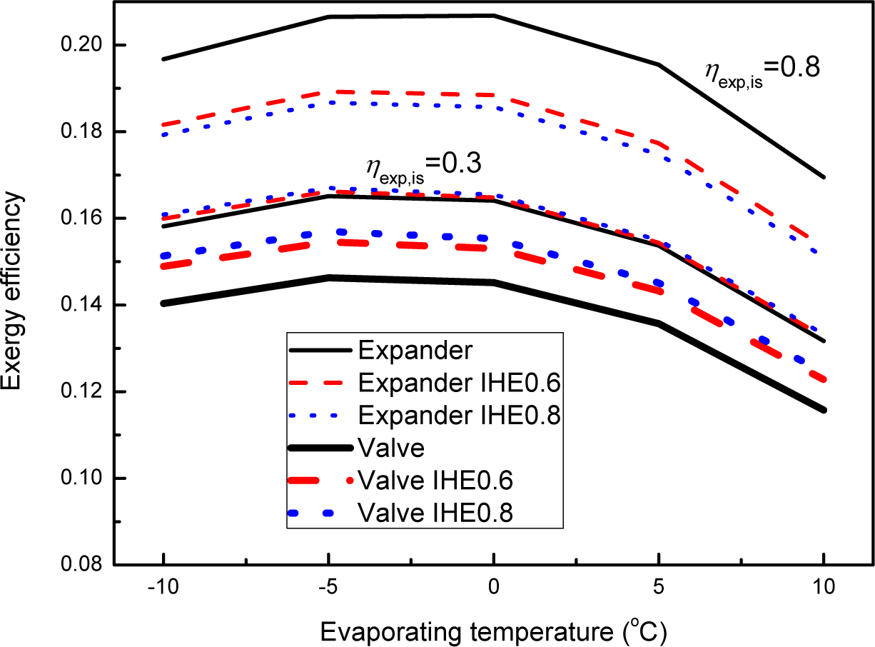
Figure 5 shows the variations of the maximum exergy efficiency
versus the evaporating temperature for different expander isentropic efficiencies at the gas cooler outlet temperature of 40 °C. It reveals that the exergy efficiency can be improved by the IHE addition for the throttle valve cycle and the expander cycle with η
exp,is = 0.3, but the IHE addition in the expander cycle with η
exp,is = 0.8 degrades the exergy efficiency under the investigated evaporating temperatures.
In the case of the effectiveness of IHE being 0.8, the use of IHE increases the exergy efficiency by about 7.26% and 1.15% averagely for the throttle valve cycle and the expander cycle with ηexp,is = 0.3 respectively. The exergy efficiency declines by 9.99% after the use of IHE for the expander cycle with ηexp,is = 0.8.
Table 1 gives the specific work terms and cooling capacities of the investigated cycles at an evaporating temperature of 5 °C and gas cooler outlet temperature of 40 °C. For the basic cycle, the addition of IHE increases the cooling capacity and the specific compression work by 33.6% and 24.9% respectively. Thus an enhancement of COP by 7.0% is gained. For the expander cycle with η
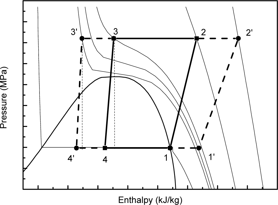
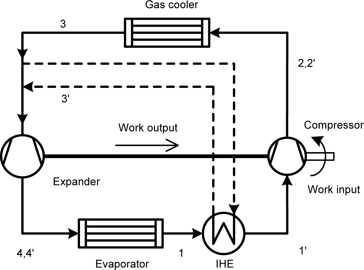
exp,is = 0.8, the addition of IHE results in an increase of the cooling capacity and the specific compression work by 32.8% and 29.2% respectively, but a decrease of the output expansion power by 30.6%. It implies that the increase in specific cooling capacity is counteracted by the decrease in expander output power and the increase in compression work, which lowers the cycle COP by 10.5%. This phenomenon can be explained through the pressure-enthalpy diagram (
Figure 6) where the cycle without IHE is expressed by the continuous line (1-2-3-4-1), the cycle with IHE is indicated by the broken line (1-1′-2′-2-3-3′-4′-4-1). It can be seen that the IHE moves the expansion process to the left and the compression process to the right. The slope of the isentropic line in the p-h diagram increase from right to left, which leads to an increase in compression work and a decrease in expander output power.
Table 2 shows the exergy losses in each process in the investigated cycles at an evaporating temperature of 5 °C, gas cooler outlet temperature of 40 °C, reference environment temperature of 300 K and the refrigerated object temperature of 283 K. It can be seen that the exergy loss in each process (except the expansion process) increases after the IHE is used for the basic cycle and the expander cycle. The IHE addition can lead to about 30% reduction in the exergy loss of the expansion process for the two cycles. The total exergy losses are increased by 23.5% and 52.4% respectively for the basic cycle and the expander cycle after the IHE is employed.
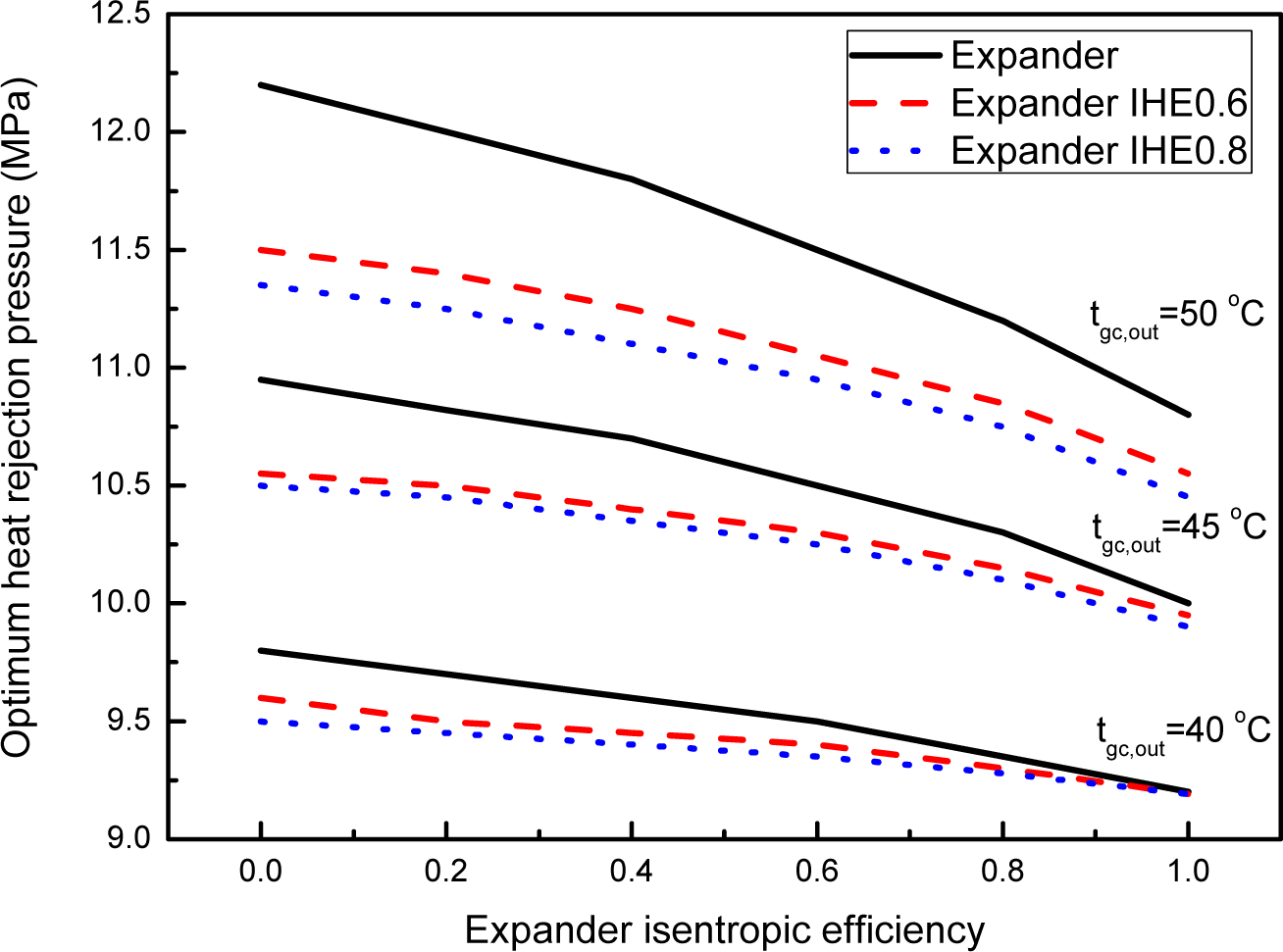
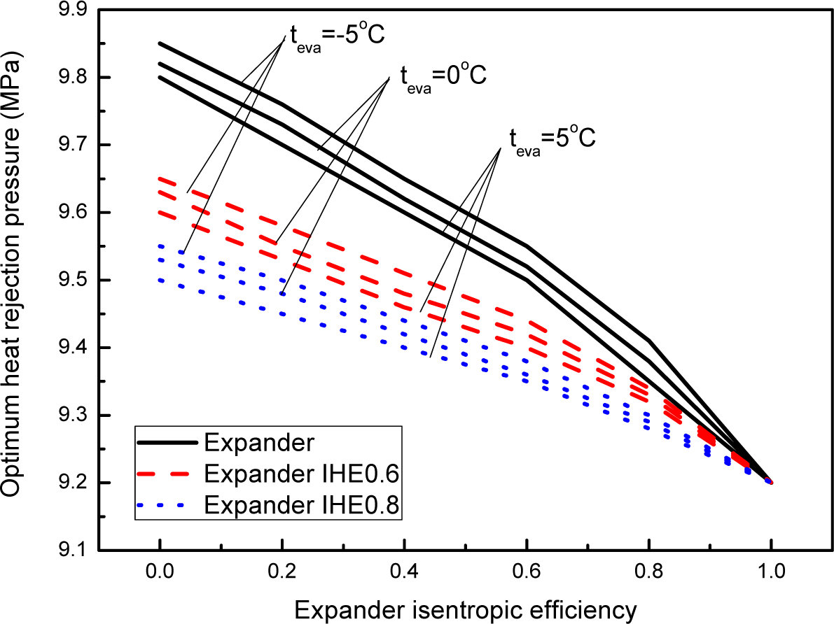
Figure 7 shows the variations of the optimum heat rejection pressure (the pressure where COP reaches the maximum value)
versus expander isentropic efficiency for different gas cooler temperatures at an evaporating temperature of 5 °C.
Figure 8 shows the variations of the optimum heat rejection pressure
versus expander isentropic efficiency for different evaporating temperatures at a gas cooler outlet temperature of 40 °C. It is seen that along with the growing of the expander isentropic efficiency, the optimum heat rejection pressure decreases. Furthermore, the increase of gas cooler outlet temperature substantially increases the optimum heat rejection pressure. Whereas the evaporating temperature has relatively less influence on the optimum heat rejection pressure compared with the gas cooler outlet temperature. The addition of IHE brings about a decrease in the optimum heat rejection pressure. Moreover, the optimum heat rejection pressure further shifts to lower values for a more efficient IHE. At the same evaporator pressure, lower heat rejection pressure results in higher compressor isentropic efficiency and lower throttling loss.
However, it can be seen from
Figures 6 and
7 that the decrease degree of the optimum heat rejection pressure owing to the addition of an IHE becomes smaller along with the increase of the expander isentropic efficiency. For example, at an expander isentropic efficiency of 0, the optimum heat rejection pressure decreases by 3.06%, 4.11% and 6.97% respectively for a gas cooler outlet temperature of 40 45 and 50 °C owing to the addition of an IHE with an efficiency of 0.8. The three percentages become 0.11%, 1% and 3.24%, respectively, at an expander isentropic efficiency of 1.0. This implies that the positive effect of the decrease of the optimum heat rejection pressure owing to an IHE addition becomes weaker along with the increase of the expander isentropic efficiency.
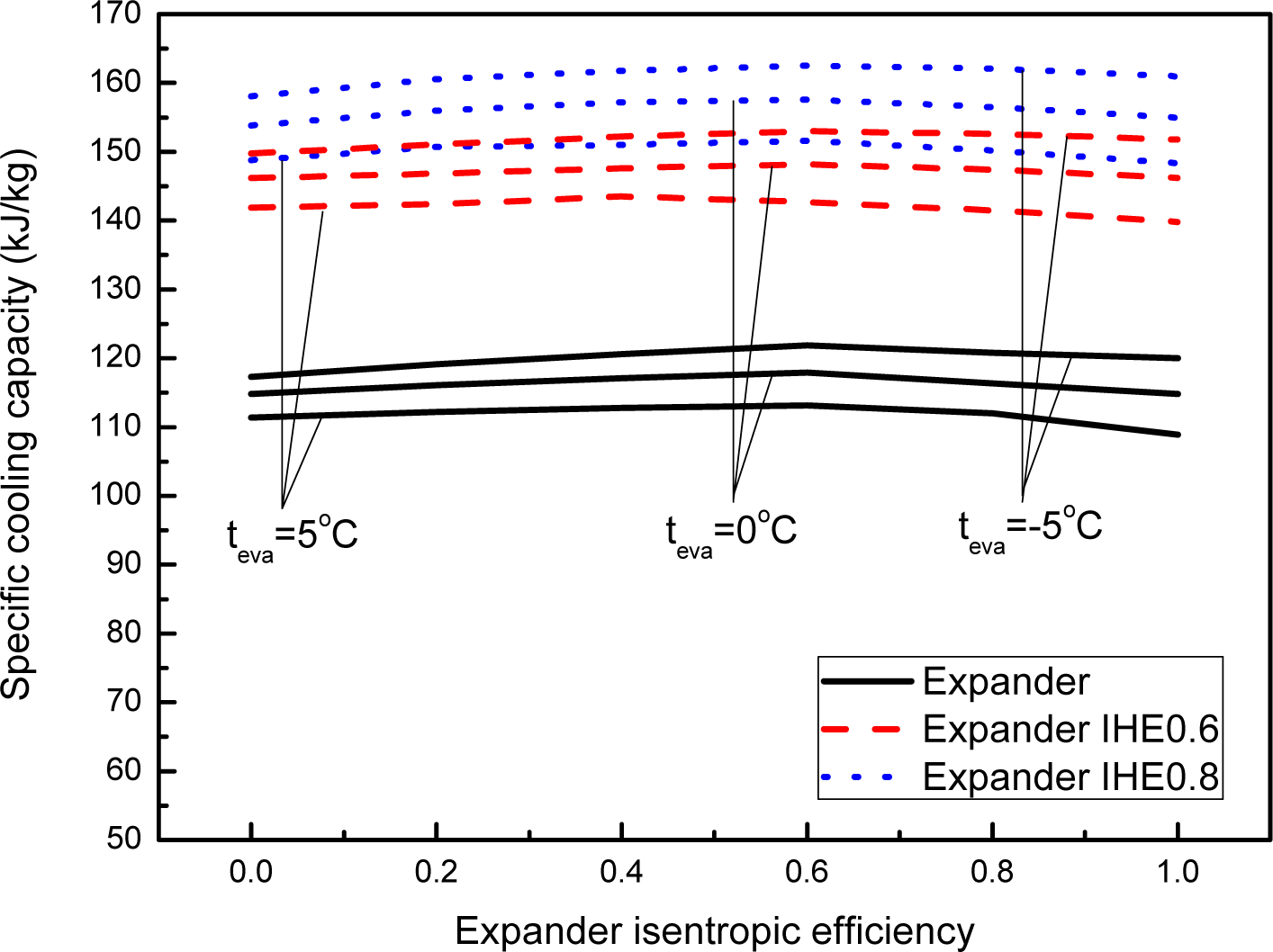
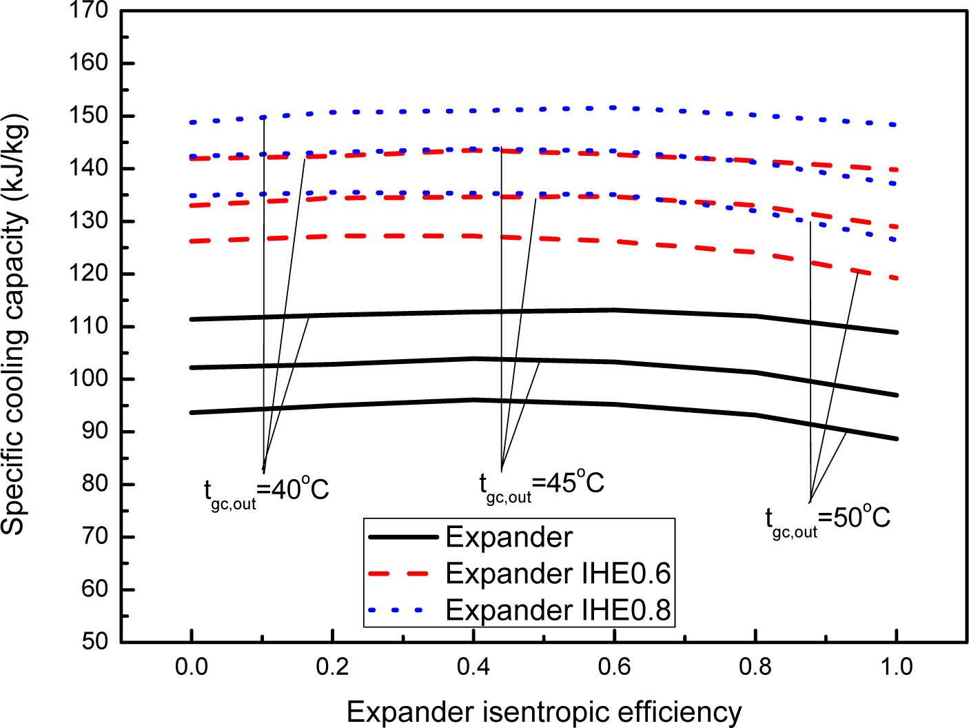
Figure 9 shows the variations of the specific cooling capacity with the expander isentropic efficiency for different gas cooler outlet temperatures at an evaporating temperature of 5 °C.
Figure 10 shows the variations of the specific cooling capacity with the expander isentropic efficiency for different evaporating temperatures at a gas cooler outlet temperature of 40 °C. It can be seen that there is marginal variation in specific cooling capacity with expander isentropic efficiency, whereas a significant rise is observed owing to the IHE addition. The specific cooling capacity increases by 25.5%–34.8% at IHE efficiency of 0.6 and 29.2%–44.1% at IHE efficiency of 0.8 compared with that of the basic cycle. It implies that more capacity could be gained from the same scale of the cycle with IHE.
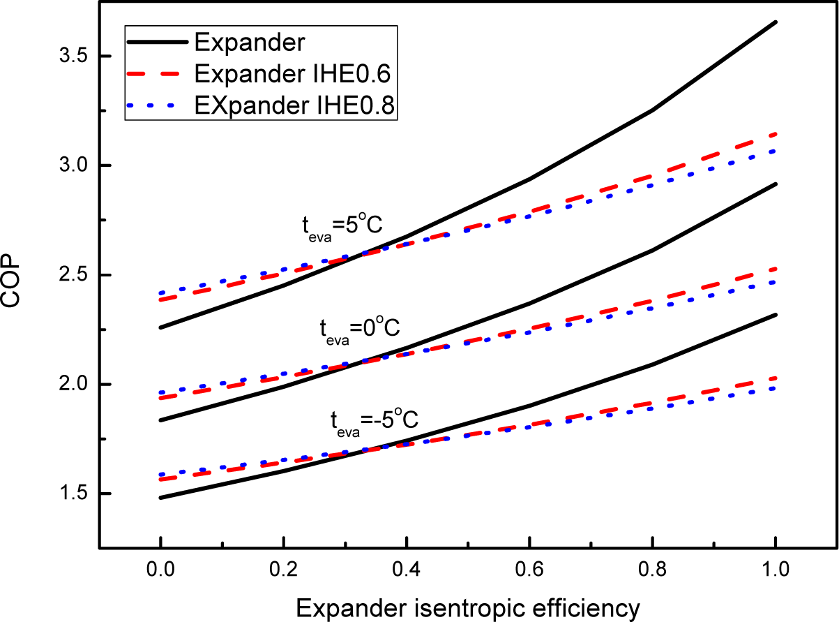
Figures 11 and
12 show the variations of the calculated system maximum COP with the expander isentropic efficiency at different gas cooler outlet temperatures and evaporating temperatures respectively. For the throttle valve cycle (η
exp,is = 0) , the maximum COP benefits from an IHE addition at all the investigated conditions. The throttle valve cycle with IHE provides a 5.6% to 17% increase in maximum COP compared to that of the basic cycle. As the expander isentropic efficiency increases, the corresponding system COP increases, but the benefit of an IHE addition decreases. If the isentropic efficiency of the expander exceeds a certain value η
exp,is,c, the performance of a CO
2 expander system does not benefit from an IHE. Instead, the IHE addition will result in a cycle COP penalty. For the ideal expander cycle (η
exp,is = 1) with IHE, the maximum COP is approximately 12.3% to 16.1% lower than the maximum COP of the cycle without IHE. At temperatures of t
gc,out = 40 °C and t
eva = 5 °C, the certain expander isentropic efficiency η
exp,is,c is about 0.35, and this value increases with the increasing of gas cooler outlet temperature, but it is almost constant with the variations of the evaporating temperature. At temperatures of t
gc,out = 50 °C and t
eva = 5 °C, this value becomes about 0.6. This finding implies that whether the energy efficiency of the expander cycle by an IHE can be improved depends on the isentropic efficiency level of the expander. The use of IHE is only profitable in the cases of lower expander isentropic efficiencies or higher gas cooler exit temperatures for the expander cycle from the view of energy efficiency.

