Article

Choked Flow Characteristics of Subcritical Refrigerant Flowing Through Converging-Diverging Nozzles

1
Institute of Architecture and Civil Engineering, Hebei United University, Tangshan 063009, China
2
Department of Foreign Languages, Tangshan College, Tangshan 063000, China
*
Author to whom correspondence should be addressed.
Entropy 2014, 16(11), 5810-5821; https://doi.org/10.3390/e16115810
Submission received: 10 August 2014 / Revised: 17 October 2014 / Accepted: 29 October 2014 / Published: 4 November 2014

Abstract

:
This paper presents the experimental results the choked flow characteristics of a subcritical refrigerant through a converging-diverging nozzle. A test nozzle with a throat diameter of 2 mm was designed and developed. The influence of operating conditions on the choked flow characteristics, i.e., the pressure profile and mass flow rate under choked flow conditions are investigated. The results indicate that the choked flow occurs in the flow of subcritical refrigerant through nozzles under the normal working conditions of air-conditioners or heat pumps. The pressure drop near the throat is about 80% of the total pressure drop through the nozzle. The critical mass flux is about 19,800 ~ 24,000 kg/(s·m2). The critical mass flow rate increases with increasing the upstream pressure and subcooling. Furthermore, the relative errors between the model predictions and the experimental results for the critical mass flux are also presented. It is found that the deviations of the predictions for homogeneous equilibrium model and Henry-Fauske model from the experimental values are −35% ~ 5% and 15% ~ 35%, respectively.

1. Introduction

One of the major contributors to the inefficiencies of the basic vapor compression refrigeration cycle is the throttling loss that results from the isenthalpic expansion from the condensing pressure to the evaporating pressure in the throttling valve. To reduce this loss, two phase energy recovery expanders [18] or ejectors [911] replacing the throttling valve have been widely investigated. Flashing flow nozzles are the core part of the impulse turbo expander [1214] or ejector. In the nozzles, the potential energy of the incoming high-pressure subcooled or saturated liquid flow is converted to the kinetic energy of the exiting liquid-vapor flow. This behavior is defined as a flashing acceleration process. If the downstream pressure is low enough, the liquid will experience a drastic phase transformation process and the mass flux will not be increased by reducing the downstream pressure any more, i.e. the choked flashing flow. In this circumstance, the flow of refrigerant through the nozzles corresponds to the critical mass flux, which is the highest flux that can be achieved by decreasing the downstream pressure under given upstream conditions. To obtain appropriate running and performance conditions of expansion work recovery devices, the flow of refrigerant should be a choked flow. Consequently, a deep understanding of the choked flow characteristics of the refrigerant through a converging-diverging nozzle is very important for the optimum design of the impulse turbo expanders or ejectors.
To the best of the authors’ knowledge, studies on refrigerant choked flashing flow through converging-diverging nozzles are still limited. Nakagawa and Takeuchi [15] investigated the effect of diverging part length on the performance of converging-diverging nozzles for the ejector-expansion refrigeration cycle using R134a. They concluded that the nozzle efficiency increases with the diverging part length owing to the mechanism that the longer diverging part provides a longer period of time for the two-phase flow to attain equilibrium. Nakagawa and Morimune [16] found that a larger diverging angle gave a higher nozzle efficiency for two-phase flow of R744.
Lucas and Koehler [17] found that choked flashing flow existed inside the motive nozzle during their experimental process of the R744 ejector expansion refrigeration system. Lee et al. [18] presented the experimental results of the R744 ejector expansion refrigeration system, and found that the choked flow appeared when the motive nozzle throat diameter is less than 1.0 mm, but disappeared when the nozzle throat diameter is over 1.0 mm. Chaiwongsa and Wongwises [19] investigated the effects of throat diameter of the motive nozzle on the performance of R134a ejector expansion refrigeration system. The motive nozzle throat area of the tested ejector is designed according to the Henry-Fauske model [20]. They found that the heat sink temperature has insignificant effects on the primary mass flux, i.e. choked flow occurred.
Ozaki et al. [21] reported that the relative error between homogeneous equilibrium model (HEM) [22] predictions of the critical nozzle flow rate and their tested data was within 5% in the R744 ejector expansion refrigeration system. Elbel et al. [23] investigated the critical mass flux of the converging-diverging motive nozzle in the R744 ejector expansion refrigeration systems, and found that the deviations of the HEM predictions and the Henry-Fauske model predictions from the experimental mass flow rates are −10% ~ −20% and −5% ~ −10% respectively. Kornhauser and Harrell [24] found that the deviations of the experimental mass flow rate values from the HEM predictions are about 10% in their R134a ejector expansion refrigeration systems. Pottker et al. [25] reported the experimental results of the R410A ejector expansion refrigeration system, and found that experimental mass flow rate through the nozzle is lower than Henry-Fauske model prediction, but the error was not presented. He et al. [26] investigated the effect of inlet subcooling degree on the performance of the converging-diverging nozzle in the R410A refrigeration experimental system, and found that, with the increase of the inlet refrigerant subcooling degree, the mass flow rate through the nozzle increased, but the nozzle efficiency decreased.
As described above, it can be clearly seen that previous published papers have reported the choked flow characteristics of transcritical R744 through a converging-diverging nozzle. However, the studies on subcritical refrigerants inside converging-diverging nozzle have been investigated by only a few previous research works. Especially, subcritical refrigerants are extensively used in the air conditioners and heat pumps at present, so the metastability effects might be more significant when subcritical refrigerants are used as the working fluid. The main purpose of the present paper is to study the subcritical refrigerant choked flow characteristics inside converging-diverging nozzles, including pressure distributions, mass flow rate and choked flow model. The effects of the relevant parameters, i.e., upstream pressure, downstream pressure, and subcooling on pressure distribution and mass flow rate that have never been presented before are also investigated.

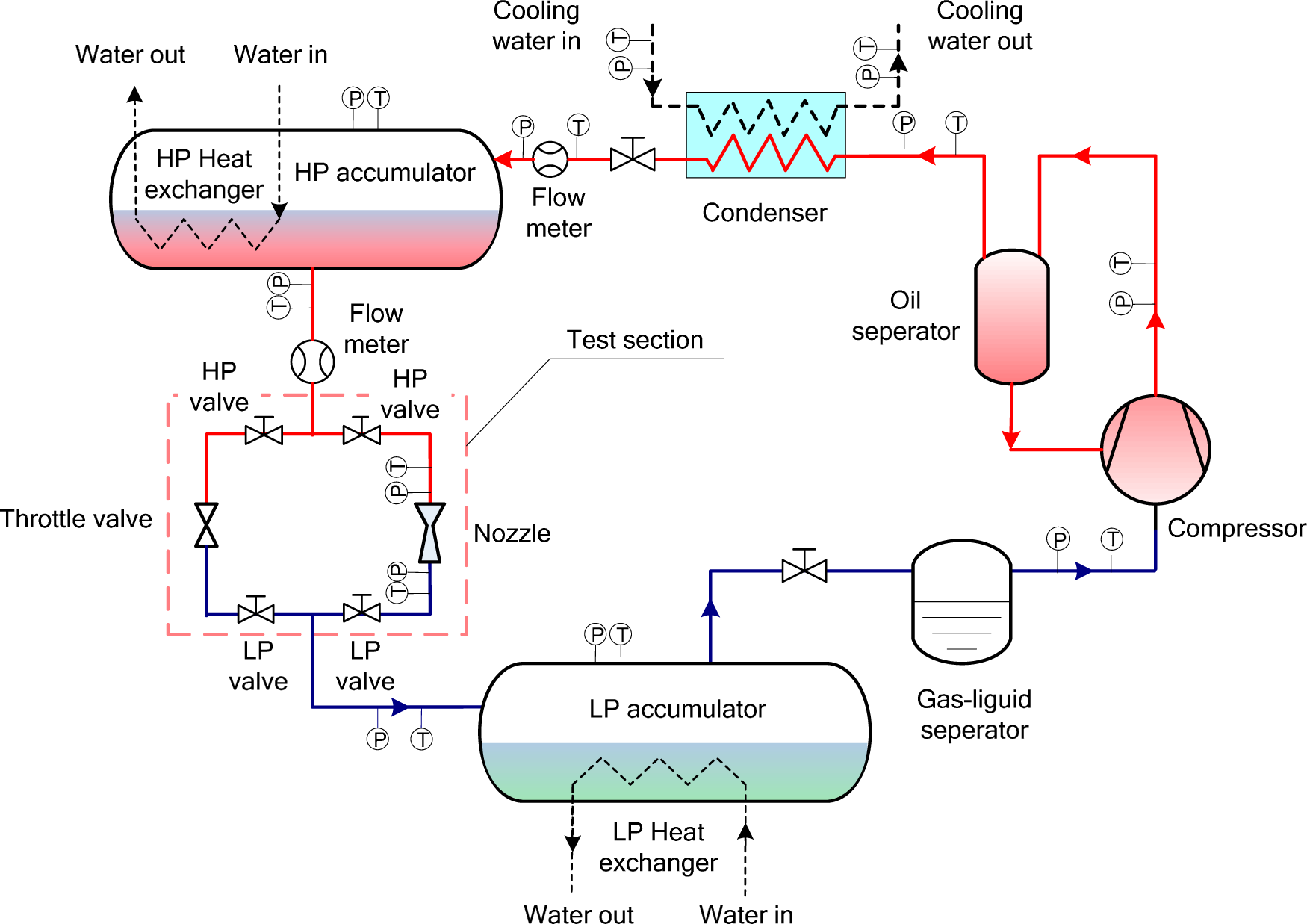
2. Experimental Setup

2.1. Experimental Apparatus and Procedure

The schematic diagram of the experimental apparatus is shown in Figure 1. The system consisted of an HP accumulator, an LP accumulator, a plate heat exchanger (condenser), a compressor and other accessory parts. The compressor is a prototype semi-hermetic reciprocating type compressor. The displacement of the compressor is 84.7 m3/h at 1450 RPM. The HP accumulator and LP accumulator has a volume of 0.56 m3. An oil separator is used to ensure low oil contamination in the circulating refrigerant, although the oil content is not measured.
If the liquid level of the HP accumulator is too low to maintain normal running during the experiment, the HP valve and the LP valve are closed and the other valves are opened. The refrigerant is sucked and compressed by the compressor. The high pressure hot vapor discharged by the compressor is cooled in the condenser. The saturated liquid refrigerant then enters the HP accumulator. When the pressure and the liquid level inside the HP accumulator achieve the required conditions, the compressor is powered off.
For an experimental run, the HP valve and the LP valve through the tested nozzle are opened, whereas other valves are kept closed. The high pressure subcooled liquid refrigerant from the HP accumulator is introduced into the tested converging-diverging nozzle. The pressure at the inlet of the test section (upstream or HP accumulator pressure) is controlled by adjusting the temperature and flow rate of the water entering the HP heat exchanger. After passing through the nozzle, the refrigerant flows into the LP accumulator. The pressure at the outlet of the test section (downstream or LP accumulator pressure) is controlled by adjusting the temperature and flow rate of the chilled water entering the LP heat exchanger. As the flow rate through the nozzle is small and the volume of the HP accumulator is quite large, the amount of liquid removed from the HP accumulator during an experiment will not influence the HP accumulator pressure. During a typical experiment, the HP accumulator pressure remained almost constant. A commercial R22 is used as the working fluid of the tested cycle owing that it is widely used in current refrigeration systems and heat pumps in China.

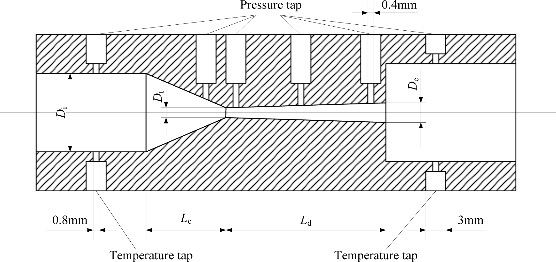
2.2. Nozzles Used in the Experiment

A converging-diverging brass nozzle is used in the experiment. The shape and geometric parameters of the nozzle of the section view are shown in Figure 2. The area of the nozzle throat is designed using the Henry-Fauske model. The other cross-sectional areas of the nozzle are calculated by using HEM. The remaining geometric parameters, including the lengths of each section, the converging angle and the diverging angle, are based on the suggestions of Nakagawa and Takeuchi [15] and Chaiwongsa and Wongwises [19]. Table 1 shows the values of the main geometric parameters of the tested nozzle.
There are four pressure taps located throughout the nozzle length such that the pressure profile along the length of the nozzle can be measured. These pressure taps are drilled with 0.4 mm diameter using a wire cutting machine. Pressure/temperature taps located before and after the nozzle are drilled to 0.8 mm such that upstream and downstream pressures/temperatures could be measured. The pressure along the nozzle is measured by pressure sensors calibrated from 0 to 2.0 MPa with an accuracy of ±0.15% full scale. The temperatures are measured by calibrated T-type thermocouples having accuracy of ±0.1 °C. The thermocouple probes were mounted in the refrigerant line to measure accurately the refrigerant temperature. The flow rate of the refrigerant through the nozzle is measured by a Coriolis mass flow meter with an accuracy of ±0.25% full scale (0.25–13 kg/min). All the signals are treated by a data acquisition instrument.

3. Results and Discussion

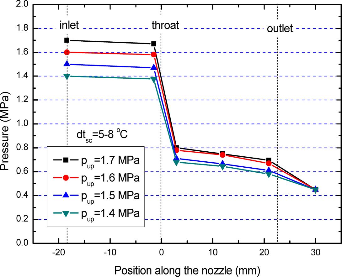
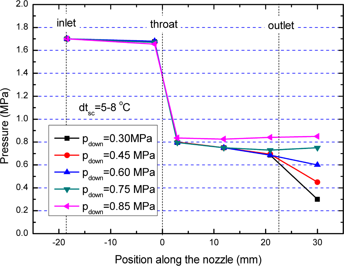
3.1. Pressure Profile
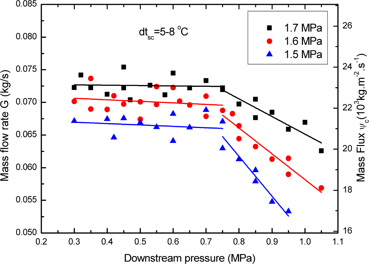
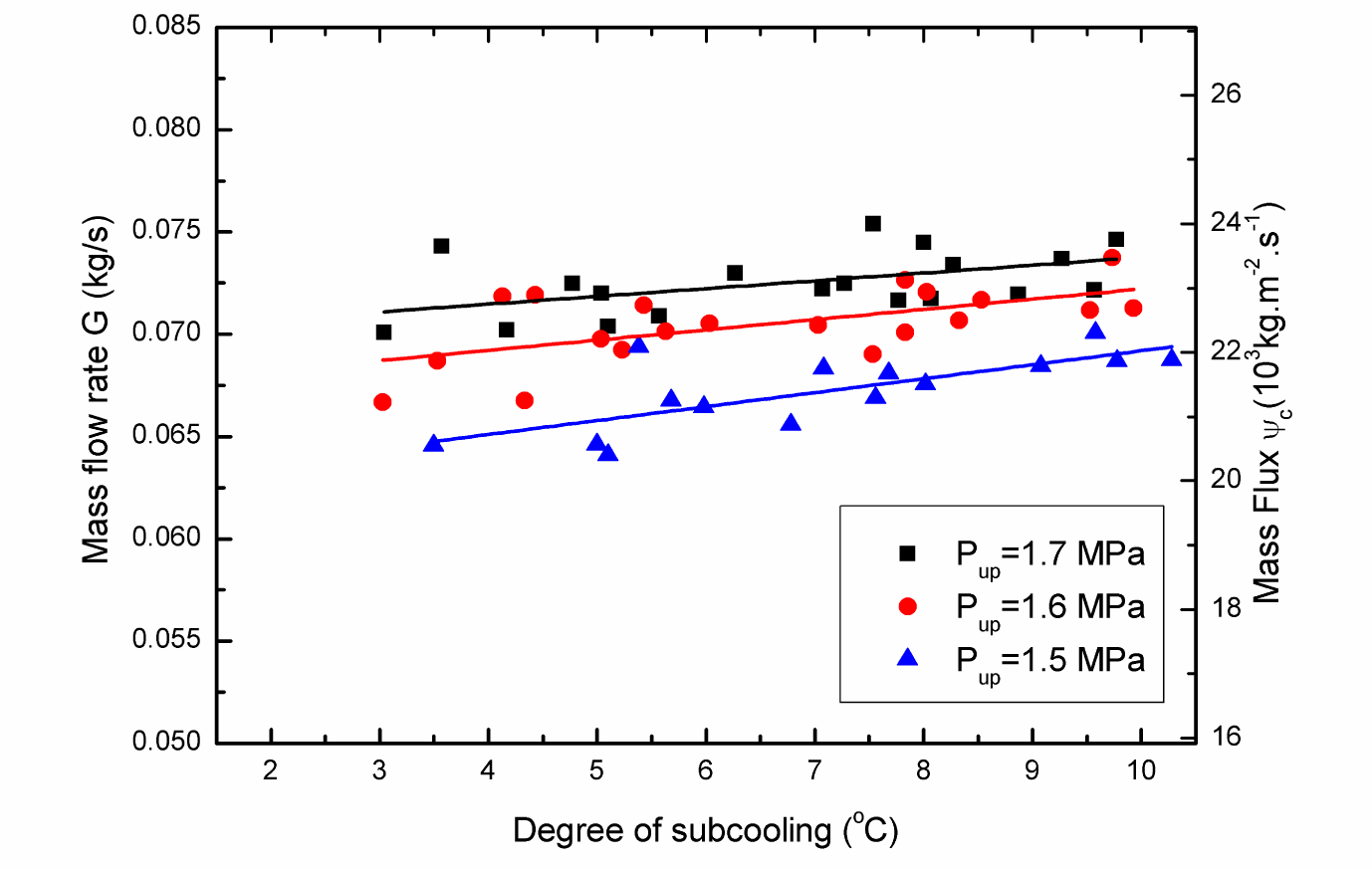
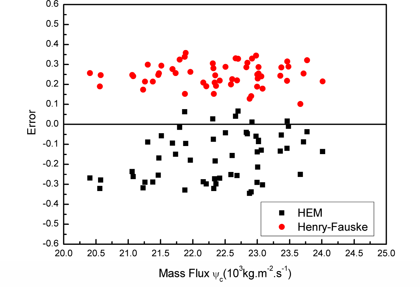
Figure 3 shows the experimental pressure profiles through the nozzle at different downstream pressures. The upstream pressure is kept constant at 1.7 MPa. The upstream subcooling, dtsc = tsat − t, is kept at 5–8 °C. It is found that the pressure initially decreases slightly in the converging part and then drops greatly at the throat. This behavior implies that the phase change starts near the throat. The noticeable pressure drop near the throat is caused by the mechanism that when the vapor phase appears in the liquid phase, the liquid phase hardly accelerates to match the abrupt increase of the specific volume. When the downstream pressure is less than a certain value, the pressures in the diverging part decrease linearly. The variation in downstream pressure has little effect on the pressure profile along the nozzles, i.e., the change of downstream condition is very little transferred to the upstream. Thus it can be concluded that the choked flow occurs in the flow of subcritical refrigerant through the nozzle in a normal working condition of air-conditioners or heat pumps. When the downstream pressure is higher than a certain value, the pressure in the diverging part initially decreases and then increases gradually, indicating that a shock wave occurred [27]. Increasing the downstream pressure in this situation leads to the increase of the pressure in the nozzle diverging part.
Figure 4 shows the experimental pressure profiles throughout the nozzle for different upstream pressures. The upstream subcooling is kept at 5–8 °C. The downstream pressure is kept constant at 0.5 MPa. It is found that the increase of upstream pressure causes the pressure at each position along the nozzle to increase, and the pressure drop throughout the nozzle to become higher. The pressure drop throughout the nozzle is about 1.02, 0.92, 0.91 and 0.82 MPa at upstream pressures of 1.7, 1.6, 1.5 and 1.4 MPa, respectively. The pressure difference before and after the throat is about 80% of the total pressure drop through the nozzle.

3.2. Mass Flow Rate

Figure 5 shows the variations of the experimental mass flow rate with the downstream pressure at different upstream pressures. The upstream subcooling is kept at 5–8 °C. It can be seen that the mass flow rate at each upstream pressure initially increases with decreasing downstream pressure, but becomes nearly constant at about 0.75 MPa. It can be deduced that choked flow occurs in the nozzle. This flow behavior is consistent with the results of past research [28,29]. The maximum mass flow rate is called the critical mass flow rate. It can be seen that the mass flow rate increases with the upstream pressure. The critical mass flow rate increases averagely by about 11.1% as the upstream pressure is varied from 1.5 MPa to 1.7 MPa. This is due to the mechanism whereby the pressure drop through the nozzle and the density at the nozzle inlet increase. The critical mass flux is about 19,800~24,000 kg/(s·m2) under the normal working condition of air-conditioners and heat pumps.
Figure 6 shows the relationship between the critical mass flow rate and the subcooling at different upstream pressures. The downstream pressure is kept constant at 0.5 MPa. It can be seen that the critical mass flow rate increases as the subcooling increases, showing an increase of about 3.7–7.4% when the subcooling changes from 3 °C to 10 °C. The general trend of mass flow rate versus subcooling is consistent with the cited literature [26]. The density of the refrigerant is increased with increasing subcooling. The delay in vaporization of the refrigerant increases as the subcooling is increased, which leads to the lessening of the flashing vapor generated. These two effects lead to the increase of the critical mass flow rate.
HEM [22] and Henry-Fauske model [20] are the two common methods to predict the critical mass flux of the nozzles. Thus the experimental values are compared to the calculated results of the two models in this paper. The choked mass flux prediction of HEM [22] is:
ψ c 2 = { [ x ( v g p ) s + ( v g v l ) ( x p ) s + ( 1 x ) ( v l p ) s ] } t 1
The Henry-Fauske model [20] takes thermodynamic non-equilibrium effects into account. Their iterative set of equations used to determine the critical flux for an initially subcooled liquid is shown in Equation (2) through Equation (4):
ψ C 2 = [ ( v g E v l 0 ) N s g E s l E d s l E d p ] t 1
p t p 0 = 1 v l 0 ψ c 2 2 p 0
x E t = s 0 s l E s g E s l E
The quantity N describes the partial phase change occurring at the throat. It is correlated as a function of throat equilibrium quality, xEt. For throat equilibrium qualities greater than 0.14, N is set equal to unity. Otherwise:
N = x E t / 0.14
In order to calculate the critical mass flux of the two models, the refrigerant temperature and pressure at the nozzle inlet must be measured. The iterations of the two models are started by assuming a certain throat pressure. When combined with the isentropic flow assumption, other fluid properties can be calculated. For HEM, the throat pressure is iterated until the mass flux reaches a maximum which is the critical mass flux of the nozzle. For Henry-Fauske model, the throat pressure is iterated until the mass fluxes calculated by Equations (2) and (3) are equal. This value represents the critical mass flux which occurs for choked nozzle flow. The relative error between the model predictions and the experimental results for the critical flux is defined as:
ε = ψ c a l ψ e x ψ e x
where ψcal represents the calculated value by HEM [22] or Henry-Fauske model [20]. Figure 7 presents the values of the relative errors between the model predictions and the experimental results for the critical mass flux. It can be seen that HEM tends to underpredict the critical mass flux, which is consistent with the published literatures [23,24]. This phenomenon is mainly because the homogeneous flow assumption neglects possible flashing delays caused by metastability [28,29], which results in the largest possible amount of vapor in the nozzle throat. For HEM, the discrepancies between the predicted values and the experimental results for the critical mass flux are in the range of −35% ~ 5% for most of the data points. The existence of a fraction of positive error is due to the fact that the upstream refrigerant is almost saturated. That is, flashing may occur before the refrigerant flows into the nozzle owing to the pressure loss at the nozzle inlet. The Henry-Fauske model overpredicts the critical mass flux, which coincides with the published literature results [25]. This is mainly because the Henry-Fauske model takes the metastability effects of the flashing flow into account. The empirically determined parameter limits the amount of vapor created by flashing during the rapid expansion process. For the Henry-Fauske model, the deviations of the predicted values from the experimental results are between 15% and 35% for most of the investigated data points.

4. Conclusions

This paper presents the experimental results of the choked flow characteristics of a subcritical refrigerant through a converging-diverging nozzle. The influence of operating conditions on the choked flow characteristics, i.e., the pressure profile and mass flow rate under choked flow conditions are investigated. The results indicate that the choked flow occurs in the flow of a subcritical refrigerant through the nozzle under the normal working conditions of air-conditioners or heat pumps. The pressure difference before and after the throat is about 80% of the total pressure drop through the nozzle. The critical downstream pressure is about 0.75 MPa. The mass flow rate increases with increasing the upstream pressure and subcooling. Furthermore, the relative errors between the model predictions and the experimental results for the critical mass flux are also presented. It is found that the deviations of the predictions for HEM and Henry-Fauske model from the experimental values are −35% ~ 5% and 15% ~ 35%, respectively.

Acknowledgments

The authors appreciate the support of Natural Science Foundation of Hebei Province (No. E2014209044, No. E2014209089), Tangshan Science and Technology Research Projects (No. 13130299b), and Natural Science Foundation of China (No.51378172).

Nomenclature

HEM
homogeneous equilibrium model
G
mass flow rate, kg/s
N
quantity
p
pressure, MPa
s
entropy, kJ/(kg.K)
v
specific volume, m3/kg
x
vapor quality
ψ
mass flux, kg/(s.m2)

Subscripts

0
stagnation
C
critical point
cal
calculated value
down
downstream
E
equilibrium
ex
experimental value
g
vapor phase
l
liquid phase
s
isentropic process
sat
saturated
sc
subcooling
t
throat
up
upstream

Author Contributions

Zhenying Zhang and Lili Tian did the theoretical work and wrote this paper. Lirui Tong and Yanhua Chen assisted with the editing of the manuscript. All authors have read and approved the final manuscript.

Conflicts of Interest

The authors declare no conflict of interest.

References

  1. Zhang, Z.; Ma, Y.; Li, M.; Zhao, L. Recent advances of energy recovery expanders in the transcritical CO2 refrigeration cycle. HVAC&R Res. 2013, 19, 376–384. [Google Scholar]
  2. Zhang, B.; Peng, X.; He, Z.; Xing, Z.; Shu, P. Development of a double acting free piston expander for power recovery in transcritical CO2 cycle. Appl. Therm. Eng. 2007, 27, 1629–1636. [Google Scholar]
  3. Yang, B.; Peng, X.; Sun, S. Study of a rotary vane expander for the transcritical CO2 cycle part I: Experimental investigation. HVAC&R Res. 2009, 15, 673–688. [Google Scholar]
  4. Yang, B.; Peng, X.; He, Z. Experimental investigation on the internal working process of a CO2 rotary vane expander. Appl. Therm. Eng. 2009, 29, 2289–2296. [Google Scholar]
  5. Wang, M.; Zhao, Y.; Cao, F. Simulation study on a novel vane-type expander with internal two-stage expansion process for R-410A refrigeration system. Int. J. Refrig. 2012, 35, 757–771. [Google Scholar]
  6. Nickl, J.; Will, G.; Quack, H. Integration of a three-stage expander into a CO2 refrigeration system. Int. J. Refrig. 2005, 28, 1219–1224. [Google Scholar]
  7. Zhao, L.; Li, M.; Ma, Y.; Liu, Z. Simulation analysis of a two rolling piston expander replacing throttling valve in conventional refrigerant heat pump system. Proceedings of the International Compressor Engineering Conference at Purdue, West Lafayette, IN, USA, 16–19 July 2012.
  8. Jia, X.; Zhang, B.; Pu, L. Improved rotary vane expander for trans-critical CO2 cycle by introducing high-pressure gas into the vane slots. Int. J. Refrig. 2011, 34, 732–741. [Google Scholar]
  9. Li, D.; Groll, E.A. Transcritical CO2 refrigeration cycle with ejector-expansion device. Int. J. Refrig. 2005, 28, 766–773. [Google Scholar]
  10. Lawrence, N.; Elbel, S. Theoretical and practical comparison of two-phase ejector refrigeration cycles including first and second law analysis. Int. J. Refrig. 2013, 36, 1220–1232. [Google Scholar]
  11. Nakagawa, M.; Marasigan, A.R.; Matsukawa, T.; Kurashina, A. Experimental investigation on the effect of mixing length on the performance of two-phase ejector for CO2 refrigeration cycle with and without heat exchanger. Int. J. Refrig. 2011, 34, 1604–1613. [Google Scholar]
  12. Cho, S.Y.; Cho, C.H.; Kim, C. Performance characteristics of a turbo expander substituted for expansion valve on air-conditioner. Exp. Therm. Fluid Sci. 2008, 32, 1655–1665. [Google Scholar]
  13. Hays, L.G.; Brasz, J.J. Two-phase turbines for compressor energy recovery. Proceedings of the International Compressor Engineering Conference at Purdue, West Lafayette, IN, USA, 23–26 July 1996.
  14. He, T.; Xia, C.; Zhao, Y. An experimental study on energy recovery by a pelton-type expander in a domestic refrigeration system. HVAC&R Res. 2009, 15, 785–799. [Google Scholar]
  15. Nakagawa, M.; Takeuchi, H. Performance of two-phase ejector in refrigeration cycle. Proceedings of the 3rd International Conference on Multiphase Flow, Lyon, France, 8–12 June 1998.
  16. Nakagawa, M.; Morimune, Y. Subsequent report on nozzle efficiency of two-phase ejector used in carbon dioxide refrigerator. Therm. Sci. Eng. 2003, 11, 51–52. [Google Scholar]
  17. Lucas, C.; Koehler, J. Experimental investigation of the COP improvement of a refrigeration cycle by use of an ejector. Int. J. Refrig. 2012, 35, 1595–1603. [Google Scholar]
  18. Lee, J.S.; Kim, M.S.; Kim, M.S. Experimental study on the improvement of CO2 air conditioning system performance using an ejector. Int. J. Refrig. 2011, 34, 1614–1625. [Google Scholar]
  19. Chaiwongsa, P.; Wongwises, S. Effect of throat diameters of the ejector on the performance of the refrigeration cycle using a two-phase ejector as an expansion device. Int. J. Refrig. 2007, 30, 601–608. [Google Scholar]
  20. Henry, R.E.; Fauske, H.K. The two-phase critical flow of one-component mixtures in nozzles, orifices, and short tubes. J. Heat Transf. 1971, 93, 179–187. [Google Scholar]
  21. Ozaki, Y.; Takeuchi, H.; Hirata, T. Regeneration of expansion energy by ejector in CO2 cycle. Proceedings of the 6 th IIR-Gustav Lorentzen Conference on Natural Working Fluids at Glasgow, Glasgow, UK, 29 August–1 September 2004.
  22. Starkman, E.; Schrock, V.; Neusen, K.; Maneely, D. Expansion of a very low quality two-phase fluid through a convergent-divergent nozzle. J. Fluids Eng. 1964, 86, 247–254. [Google Scholar]
  23. Elbel, S. Historical and present developments of ejector refrigeration systems with emphasis on transcritical carbon dioxide air-conditioning applications. Int. J. Refrig. 2011, 34, 1545–1561. [Google Scholar]
  24. Harrell, G.S.; Kornhauser, A.A. Performance tests of a two phase ejector. Proceedings of the 30th Intersociety Energy Conversion Engineering Conference (IECEC), Orlando, FL, USA, 30 July–4 August 1995; pp. 49–53.
  25. Pottker, G.; Guo, B.; Hrnjak, P.S. Experimental investigation of an R410A vapor compression system working with an ejector. Proceedings of the International Refrigeration and Air Conditioning Conference at Purdue, West Lafayette, IN, USA, 10–11 July 2010.
  26. He, T.; Xia, C.; Ding, L.; Li, L.; Shu, P. Influence of subcooling on nozzle efficiency. J. Xi’an Jiaotong Univ. 2009, 43, 18–21. [Google Scholar]
  27. Berana, M.S.; Nakagawa, M.; Harada, A. Shock waves in supersonic two-phase flow of CO2 in converging-diverging nozzles. HVAC&R Res. 2009, 15, 1081–1098. [Google Scholar]
  28. Nilpueng, K.; Wongwises, S. Flow mechanisms of HFC-410A inside short-tube orifices during flashing process. Int. J. Heat Mass Transf. 2010, 53, 3449–3459. [Google Scholar]
  29. Singh, G.M.; Hrnjak, P.S.; Bullard, C.W. Flow of refrigerant R134a through orifice tubes. HVAC&R Res. 2001, 7, 245–262. [Google Scholar]
Figure 1. Schematic diagram of the experimental apparatus.
Entropy 16 05810f1
Figure 2. Section view of the tested nozzle.
Entropy 16 05810f2
Figure 3. Pressure profiles throughout the nozzle at different downstream pressures.
Entropy 16 05810f3
Figure 4. Pressure profiles throughout the nozzle at different upstream pressures.
Entropy 16 05810f4
Figure 5. Effect of downstream pressure on mass flow rate at different upstream pressures.
Entropy 16 05810f5
Figure 6. Effect of subcooling on mass flow rate at different upstream pressures.
Entropy 16 05810f6
Figure 7. Relative errors between model predictions and experimental results.
Entropy 16 05810f7
Table 1. Values of the main geometric parameters of the tested nozzle.
ParametersValues
Dt (mm)2
Di (mm)6.5
De (mm)2.8
Lc (mm)8.4
Ld (mm)22.9

