Review

Quantum Computation-Based Image Representation, Processing Operations and Their Applications

1
School of Computer Science and Technology, Changchun University of Science and Technology, No. 7089, Weixing Road, Changchun 130022, China
2
Department of Computational Intelligence and Systems Science, Tokyo Institute of Technology, G3-49, 4259 Nagatsuta, Midori-ku, Yokohama 226-8502, Japan
3
College of Engineering, Salman Bin Abdulaziz University, P.O. Box 173, Al-Kharj 11942, Saudi Arabia
*
Author to whom correspondence should be addressed.
Entropy 2014, 16(10), 5290-5338; https://doi.org/10.3390/e16105290
Submission received: 28 June 2014 / Revised: 21 August 2014 / Accepted: 29 August 2014 / Published: 10 October 2014
(This article belongs to the Section Entropy Reviews)

Abstract

:
A flexible representation of quantum images (FRQI) was proposed to facilitate the extension of classical (non-quantum)-like image processing applications to the quantum computing domain. The representation encodes a quantum image in the form of a normalized state, which captures information about colors and their corresponding positions in the images. Since its conception, a handful of processing transformations have been formulated, among which are the geometric transformations on quantum images (GTQI) and the CTQI that are focused on the color information of the images. In addition, extensions and applications of FRQI representation, such as multi-channel representation for quantum images (MCQI), quantum image data searching, watermarking strategies for quantum images, a framework to produce movies on quantum computers and a blueprint for quantum video encryption and decryption have also been suggested. These proposals extend classical-like image and video processing applications to the quantum computing domain and offer a significant speed-up with low computational resources in comparison to performing the same tasks on traditional computing devices. Each of the algorithms and the mathematical foundations for their execution were simulated using classical computing resources, and their results were analyzed alongside other classical computing equivalents. The work presented in this review is intended to serve as the epitome of advances made in FRQI quantum image processing over the past five years and to simulate further interest geared towards the realization of some secure and efficient image and video processing applications on quantum computers.

1. Introduction

Computer science and information systems are disciplines that have penetrated into every aspect of human activities. Recently, novel methods for speeding-up certain tasks and interdisciplinary research between computer science and several other scientific fields are attracting the interest of scientists. Quantum computation is such a thriving and advancing field with a considerable number of evolutions in the past several decades [1,2]. In 1982, Feynman proposed a quantum physics-based computation model, named quantum computers, which could be more powerful than classical ones [3]. Subsequently, Deutsch suggested that the parallelism of quantum computation could be realized by using the superposition state of qubits [4]. In 1994, Shor gave a polynomial time algorithm for the integer factoring problem [5,6], and Grover developed an quantum searching algorithm to speed-up the database searching afterwards [7,8]. These are essential evidence supporting the superiority of quantum computers. More recently, many technical corporations, research institutes and even some financial groups are working on and supporting the development of quantum computers. In 2013, IBM proposed high-fidelity gates towards a scalable super-conducting quantum processor [9]. In addition, Google, NASA and several other research associations formed the Quantum Artificial Intelligence Lab with the utilization of a brand new 512-qubit D-Wave Two quantum computer. Moreover, BlackBerry billionaire, Mike Lazaridis, has set the realization of the quantum computer as the primary target of his massive investment in Quantum Valley.
A quantum computer is a physical machine that can accept input states that represent a coherent superposition of many different inputs and subsequently evolve them into a corresponding superposition of outputs [10,11]. The computation on quantum computers is composed of a sequence of unitary transformations that affects each element of the superposition simultaneously, meanwhile generating a massive parallel data processing, albeit within one piece of hardware. While bits and their manipulation on classical computing devices can be described using two constants (zero and one) and the tools of Boolean algebra, qubits, the smallest unit to facilitate computation on quantum computers must be discussed in terms of vectors, matrices and other linear algebraic constructions [12,13]. The current paradigm for implementing quantum algorithms is the quantum circuit model [13], where the algorithms are compiled into a sequence of simple gates acting on one or more qubits, such as NOT, Hadamard, Controlled-NOT and Toffoli gates [12,14].
Quantum computation and quantum information have appeared in various areas of computer science, such as information theory, cryptography, emotion representation and image processing, because inefficient tasks on classical computers can be overcome by exploiting the power of quantum computation [1519]. Quantum image processing, which utilizes the characteristic of quantum parallelism [3] to speed up many processing tasks, is a subfield of quantum information processing [15,20,21]. The first steps taken in the area of quantum image processing have involved proposals on representations to capture and store the image on quantum computers. Various representations for images on quantum computers were proposed, such as qubit lattice, wherein the images are two-dimensional arrays of qubits [20], Real Ket, wherein the images are quantum states having gray levels as coefficients of the states [22], grid qubit, in which geometric shapes are encoded in quantum states [23], quantum lattice, wherein color pixels are stored in quantum systems qubit by qubit [24], flexible representation of quantum image (FRQI), wherein the images are normalized states that capture the essential information about every point in an image, i.e., its color and position [21,25,26], and multi-channel quantum image (MCQI) [27,28], which is an extension of FRQI representation that contains the R, G and B channels for processing color information. Among them, FRQI representation is often used and thoroughly studied because it encodes quantum images of the same size using many fewer qubits in comparison with the other methods, and also, it facilitates various classical-like image processing operations. Many image processing strategies exploiting FRQI representation are developed to process transformations that target the geometric information and the color information [2932]. In addition, applications based on FRQI representation are presented, such as the watermarking strategies [3335], quantum image data searching [3638] and the framework of producing quantum movies [12,39].
The work in this paper tries to review the FRQI representation and to summarize its related transformations, operations and applications, which is organized as follows:
  • In Section 2, the basic knowledge and notations used in this paper are introduced first. In addition, the flexible representation of quantum images (FRQI), the general framework of all geometric transformations on FRQI quantum images and the efficient color transformations on FRQI quantum images are reviewed.
  • In Section 3, the extension of FRQI quantum images that allows for processing color images, the multi-channel representation for quantum images (MCQI) is introduced. What is more, quantum circuits to realize color operations on the channel of interest, channel swapping and α blending of MCQI quantum images are presented.
  • In Section 4, a method to compare multiple pairs of FRQI quantum images in parallel is discussed, where the similarities of the images are estimated through the probability distributions of the readouts from quantum measurements. It offers a significant speed-up in comparison to performing the same task on traditional computing devices by transforming multiple images in a strip simultaneously.
  • In Section 5, an FRQI quantum image searching method is presented based on the parallel comparison method introduced in Section 4. It is achieved by using low computational resources, which are only a single Hadamard gate combined with m + 1 quantum measurement operations.
  • In Section 6, we build on the pioneering watermarking and authentication strategy for FRQI quantum images, WaQI, to propose protocols that would facilitate the notion of watermarking MCQI color images. The proposed MC-WaQI is a double-key and double-domain watermarking strategy that is secure and flexible by utilizing QFT techniques and quantum measurements to watermark MCQI quantum images.
  • In Section 7, similarly, the pioneering attempt to represent and produce movies on quantum computers (quantum movie) is extended to the multi-channel color image framework. Following this, we describe a video encryption and decryption protocol on quantum computers based on color information transformations on each frame.
  • In Section 8, we conclude with some remarks on possible technologies and directions that practitioners in the area opine could be used to realize some of the FRQI-based frameworks reviewed in earlier sections. Finally, we offer a few concluding remarks.

2. A Flexible Representation of Quantum Images and Its Processing Operations

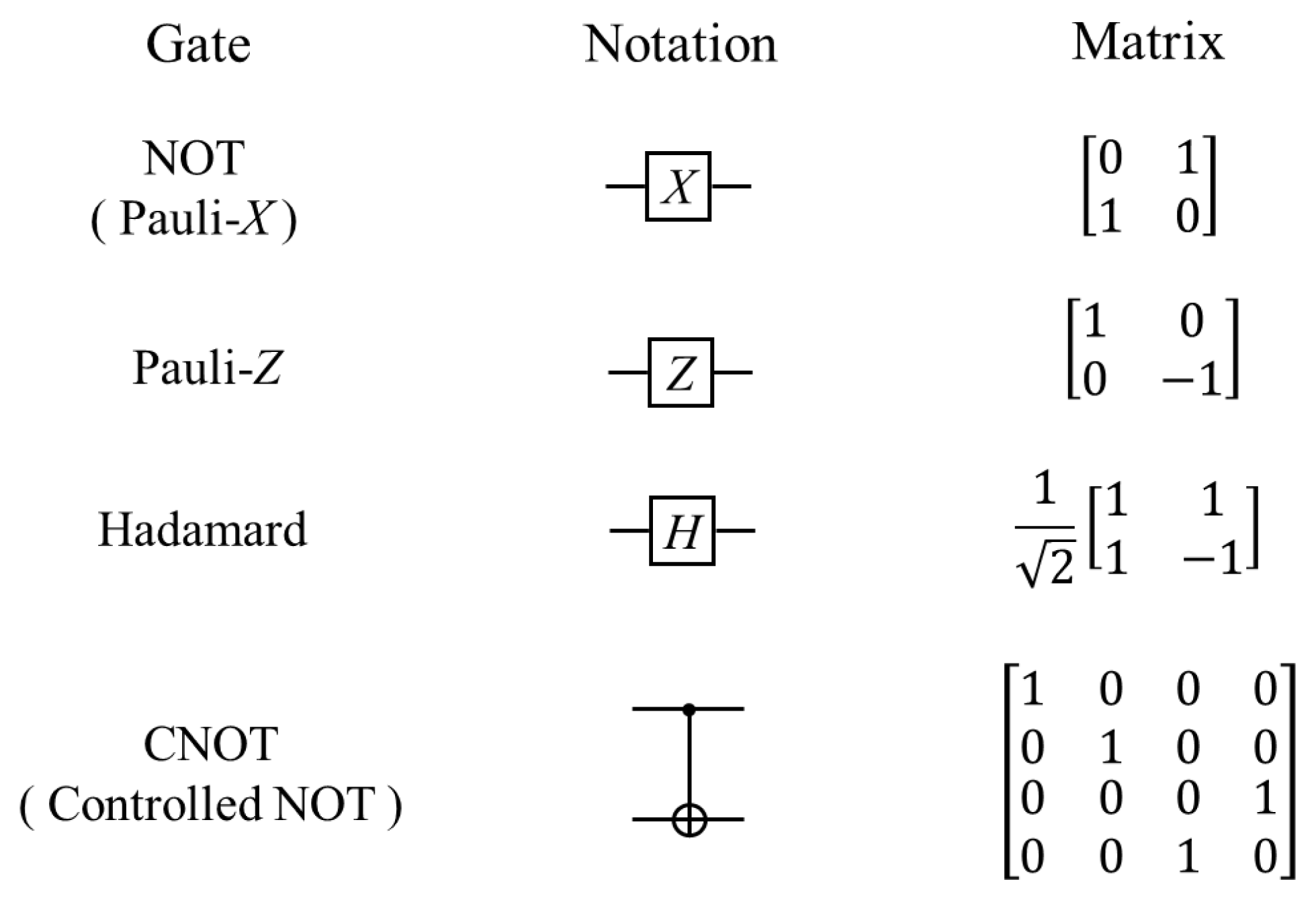
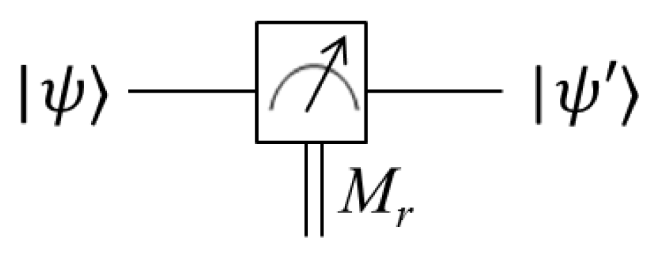
2.1. Quantum Bits and Quantum Gates

In quantum mechanics, quantum states are usually indicated using the bra-ket notation (also known as Dirac notation), which is composed of vertical bars and angle brackets. In such a symbol system, each quantum state is described as a vector in Hilbert space (called a ket, which is defined as:
u = ( u 0 u 1 u n - 1 ) , u i C , i = 0 , 1 , , n - 1.
The adjoint of ket is referred to as bra, which has the definition:
u = u * = { u 0 * u 1 * u n - 1 * } ,
where u* is the notation of complex conjugate of u.
Corresponding to the definition of a bit in conventional computation, a qubit, which is a unit vector in two-dimensional Hilbert space, is regarded as the smallest unit of information in a quantum system. It is defined by:
ψ = ( α β ) = α ( 1 0 ) + β ( 0 1 ) = α 0 + β 1 ,
where α and β are complex numbers.
In order to present the composition of quantum systems, the tensor product (notated as ⊗) is used, e.g., the tensor product of two matrices is shown as below. In addition, the tensor product of a matrix A for n times is denoted by An. Similarly, for two vectors, |u〉 and |v〉, the tensor product of them can be expressed as |u〉 ⊗ |v〉 and shortened as |u〉|v〉 or |uv〉.
A = ( a 11 a 12 a 1 m a 21 a 22 a 2 m a n 1 a n 2 a n m ) , B = ( b 11 b 12 b 1 q b 21 b 22 b 2 q b p 1 b p 2 b p q ) ,
A B = ( a 11 B a 12 B a 1 m B a 21 B a 22 B a 2 m B a n 1 B a n 2 B a n m B ) .
The commonly used quantum gates, such as NOT, Hadamard and CNOTgates in Figure 1, are often employed to break down the complex transform in the quantum circuit model into simpler ones. The gate that applies on k qubits is generally denoted as a 2k × 2k unitary matrix, in addition, the number of qubits in the input of the gate has to be equal to the output end. The mission of the final step in quantum simulation is to convert the quantum information into the classical form, which is realized by analyzing the probability distributions of the readouts from the quantum measurement. To distinguish the probabilistic classical bit from a qubit, a double-line wire is adopted, as depicted in Figure 2. The probability p of a measurement result r occurring when state ψ is measured is ψ M r M r ψ . The state of the system after measurement, |ψ′〉, is:
ψ = M r p ( r ) ψ .

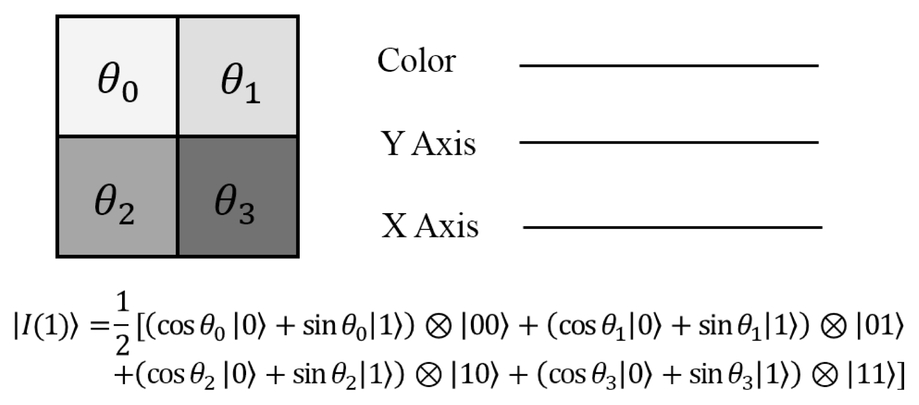
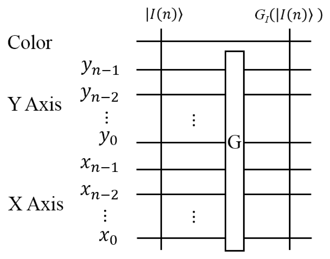
2.2. Flexible Representation for Quantum Images

The realization of most quantum image processing applications will undoubtedly rely on using their corresponding classical operations as a reference. In this subsection, a flexible representation for quantum images, FRQI [21,25,26], which is similar to the pixel representation for images on traditional computers, is introduced. It captures the fundamental information, i.e., the colors and the corresponding positions of every point in an image and integrates them into a quantum state, as defined in Equation (7),
I ( n ) = 1 2 n i = 0 2 2 n - 1 c i i ,
where
c i = cos  θ i 0 + sin  θ i 1 ,
θ i [ 0 , π 2 ] , i = 1 , 2 , 2 2 n - 1 ,
where θ is the vector of angles encoding colors and |i〉 is 2n-D computational basis quantum state to indicate the corresponding positions. For the 2D images, the position information |i〉 includes two parts: the vertical and horizontal co-ordinates. In 2n-qubit systems for preparing quantum images, the vector:
i = y x = y n - 1 y n - 2 y 0 x n - 1 x n - 2 x 0 ,
x j , y j { 0 , 1 } ,
for every j = 0, 1, . . . , n encodes the vertical location by means of the first n-qubit yn−1yn−2 · · · y0 and the location along the horizontal axis by using the second n-qubit xn−1xn−2 · · · x0. The FRQI state is a normalized state, i.e., |||I(θ)〉|| = 1, as given by:
I ( n ) = 1 2 n i = 0 2 2 n - 1 ( cos 2 θ i + sin 2 θ i ) = 1.
An example of a 2 × 2 FRQI quantum image with its quantum state is shown in Figure 3.
In quantum computation, in order to prepare a desired quantum image, it is necessary to transform quantum computers from the initialized state to the specified state. As we introduced earlier, all of the transforms in quantum computation are unitary transforms, and they are described as unitary matrices. Quantum mechanics ensure the existence of such unitary transforms by using only simple quantum gates. The polynomial preparation theorem (PPT) in Theorem 1 shows an efficient implementation of the preparation process.

Theorem 1

Given a vector θ = (θ0, θ1, · · ·, θ22n−1), (nN) of angles, there is a unitary transform ℘ that is composed of polynomial number of simple gates to turn quantum computers from the initialized state, |0〉⊗2n+1, to the FRQI state in Equation (7).
Two steps, i.e., Hadamard transforms and controlled-rotation transforms, are used to achieve the unitary transform , from which the initialized state |0〉⊗2n+1 is changed to |H〉 and then to |I(n)〉, as presented in Figure 4.
First, applying the transform = IH⊗2n, where I is the 2D identity matrix and H is the Hadamard gate, on |0〉⊗2n+1, produces the state |H〉,
( 0 2 n + 1 ) = 1 2 n i = 0 2 2 n - 1 i = H .
Then, consider the rotation matrices Ry(2θi) (along the y-axis by the angle 2θi) and controlled rotation matrices Ri (i = 0, 1, · · ·, 22n − 1),
R y ( 2 θ i ) = ( c o s θ i - s i n θ i s i n θ i c o s θ i ) ,
R i = ( I j = 0 , j 1 2 2 n - 1 j j ) + R y ( 2 θ i ) i i .
The controlled rotation Ri is a unitary matrix, since R i R i = I 2 n + 1. Applying Rk and RlRk on |H〉 provides us that:
R k ( H ) = R k ( 1 2 n 0 i = 0 2 2 n - 1 1 ) = 1 2 n [ I 0 ( i = 0 , i k 2 2 n - 1 i ) ( i = 0 2 2 n - 1 i ) + R y ( θ k ) 0 k k ( i = 0 2 2 n - 1 i ) ] = 1 2 n [ 0 ( i = 0 , i k 2 2 n - 1 i i ) + ( c o s θ k 0 + s i n θ k 1 ) k ,
R l R k H = R l ( R k H ) = 1 2 n [ 0 ( i = 0 , i k , l 2 2 n - 1 i i ) + ( c o s θ k 0 + s i n θ k 1 ) k + ( c o s θ l 0 + s i n θ l 1 ) l ] .
It is clear from Equation (17) that:
H = ( i = 0 2 2 n - 1 R i ) H = I ( n ) .
Hence, the unitary transform = turns quantum computers from the initialized state, |0〉⊗2n+1, to the FRQI state in Equation (7).

2.3. Fast Geometric Transformations on FRQI Quantum Images

Geometric transformations on quantum images (GTQI) [29] are the operations that focus on manipulating the position information of the FRQI quantum images. Using the GTQI operations, classical-like transformations, such as two-point swapping, flip, co-ordinate swapping and orthogonal rotations, can be performed on the quantum images encoded in the FRQI representation using the basic quantum gates. The geometric transformations, GI, on FRQI quantum images can be defined as in Equation (19),
G I ( I ( n ) ) = 1 2 n i = 0 2 2 n - 1 c i G ( i ) ,
where |I(n)〉 is an FRQI image as defined in Equation (7) and G(|i〉) for i = 0, 1, . . . , 22n − 1 is the unitary transformation performing geometric exchanges on the basis of the position information |i〉.
The general structure of circuits for geometric transformations on FRQI quantum images is shown in Figure 5. For an N-sized image, the detailed analysis of quantum circuits shows that the complexity is O(log2N) for two-point swapping and O(logN) for the other operations [29].
A detailed and astute understanding of the GTQI operations equips quantum circuit designers with the adroitness to realize more complex transformations, restricted GTQI (rGTQI), giving birth to more robust and advanced applications and utilities for quantum image processing. The groundwork needed for this has already been covered in available literature [33,37,40]. We refer interested readers to these insightful materials for additional information.

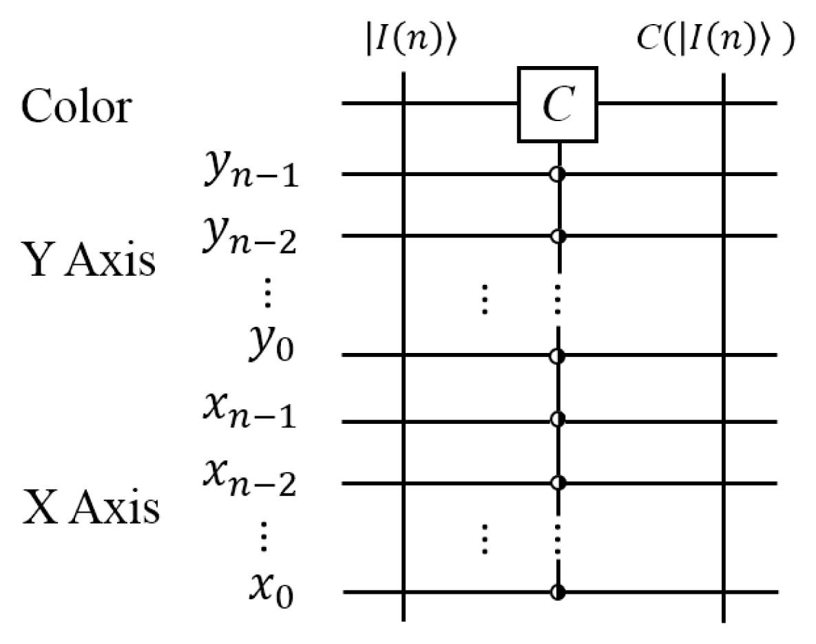
2.4. Efficient Color Transformations on FRQI Quantum Images

The GTQI transformations reviewed in the preceding subsection were focused solely on the spatial content encoded in the FRQI quantum image. Considering the FRQI representation in Equation (7), this leaves the single qubit encoding the chromatic (color) content of the image unchanged. In [30,41], color transformations, C, targeting the single qubit chromatic content of FRQI quantum images (CTQI) were proposed. This transformation was subsequently reviewed and utilized in [31,34] to focus on control condition operations on the color wire of the FRQI image, as shown in Figure 6. In this manner, the colors of every controlled position in the image are changed as defined in Equation (20),
C I ( I ( n ) ) = 1 2 n i = 0 2 2 n - 1 C ( c ( θ k ) ) i ,
where CI is the qubit gate to transform the color information in quantum image |I(n)〉 and |c(θk)〉 encodes the color information which is presented as:
c ( θ k ) = cos  θ k 0 + sin  θ k 1 .
A single qubit gate NOT gate or X gate is taken as an example to explain how the color transformation works. Its function is defined as:
X = ( 0 1 1 0 ) ,
and its property is apparently to switch the value |0〉 and |1〉 as X|0〉 = |1〉, X|1〉 = |0〉. When the NOT or X gate is applied on the color wire, its performance is:
X ( c ( θ k ) ) = c ( π 2 - θ k ) , k 0 , 1 , , 2 2 n - 1 ,
where |c(θk)〉 is the color information, as defined in Equation (21).
Interested readers are referred to the available literature, notably [30,32,34,41] for extensive discussions on the CTQI transformation, its review to adapt for use in multi-channel quantum images (MCQI) and some available applications in image watermarking and video encryption.

3. Multi-Channel Quantum Images and Related Operations

In the preceding section, the FRQI representation and transformations targeting the spatial and geometric information it encodes were briefly highlighted. While in its present form, the FRQI representation pioneered a completely new sub-field within the quantum image processing discipline with interesting applications in quantum watermarking, quantum movies, database search, and so on, it still does not capture the notion of “full” color in images.
Consequently, in order to process color images on quantum computers, a new representation encoding information from the R, G and B channels should be established, and these multi-channel information should be stored in quantum states simultaneously. Based on the FRQI representation in Section 2.2, the multi-channel representation for quantum images, MCQI [27,28], was proposed to capture the RGB channel information. This is accomplished by assigning three qubits to encode color information about images. The representation for MCQI quantum images extends the FRQI representation to the multi-color image domain and with it, comes the possibility to realize applications and protocols on multi-channel quantum images.

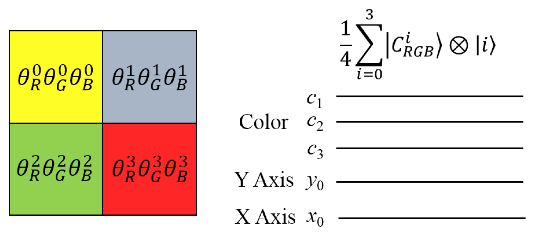
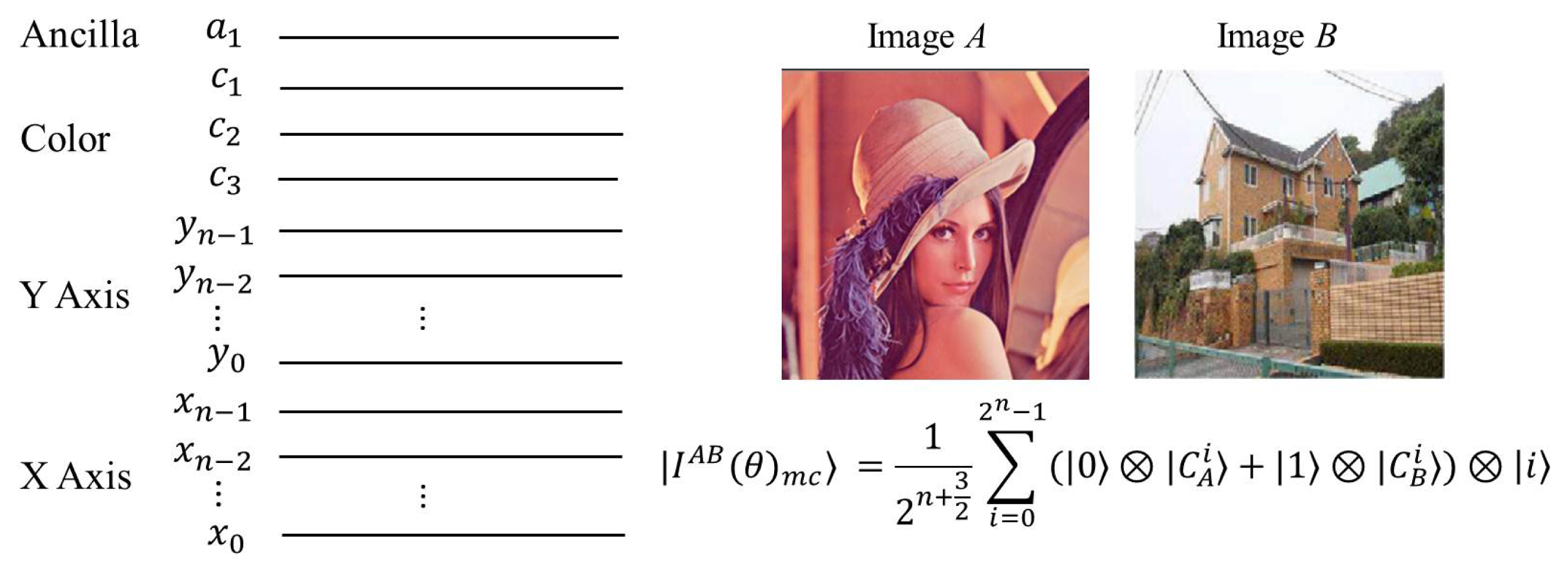
3.1. Multi-Channel Representation for Quantum Images

The multi-channel representation for quantum images (MCQI) is presented as:
I ( n ) m c = 1 2 n + 1 i = 0 2 2 n - 1 C R G B α i i ,
where the color information C R G B α i encoding the RGB channels information is defined as:
C R G B α i = cos  θ R i 000 + cos  θ G i 001 + cos  θ B i 010 + cos  θ α 011 + sin  θ R i 100 + sin  θ G i 101 + sin  θ B i 110 + sin  θ α 111 ,
where { θ R i , θ G i , θ B i } [ 0 , π / 2 ] are three angles encoding the colors of the R, G and B channels of the ith pixel, respectively, and θα is set as zero to make the two coefficients constant (cos θα = 1 and sin θα = 0) to carry no information, which is discussed in [27,28].
The general MCQI circuit is presented in Figure 7, where the first three qubits (c1, c2 and c3) are color qubits that encode RGB color information for an image, and the remaining 2n qubits (yn−1, yn−2, . . . , y0 and xn−1, xn−2, . . . , x0) are used to encode position information (Y-axis and X-axis) about pixels of a 2n × 2n image. A simple example of an MCQI quantum image with its quantum state is shown in Figure 8. The methods for storing and retrieving quantum images are discussed in [27,28,42]. Like FRQI, the MCQI state is also a normalized state, i.e., |||I(n)mc〉|| = 1, as given by:
I ( n ) m c = 1 2 n + 1 ( i = 0 2 2 n - 1 ( cos 2 θ R i + sin 2 θ R i + cos 2 θ G i + sin 2 θ G i + cos 2 θ B i + sin 2 θ B i + cos 2 0 + sin 2 0 ) ) 1 2 = 1.
An MCQI quantum image is stored in the preparation process using the MC-PPT theorem, and it is retrieved by means of the quantum measurement on each color channel of it [28]. All RGB information about an MCQI image is stored simultaneously; consequently, this makes the MCQI representation have the following advantages:
  • MCQI representation provides a solution using many fewer qubits to encode R, G and B channel information in normalized quantum states.
  • MCQI makes it easier to design color image operators with much lower complexity.
  • MCQI representation offers the potential possibility to design a quantum-cryptography-based color image watermarking algorithm.
In classical image processing, basic operators provide various fundamental manipulations for processing images, such as color changes at some positions, geometric transformations and shifting color information on any channel of interest (CoI operation). While in quantum image processing, some classical operations, e.g., convolution operators [43], are not physically possible, because they do not satisfy the basic invertible property of quantum computation.
FRQI and MCQI representations share the same method for position information encoding, i.e., the same arrangement for position qubits, and differences between the two representations are color qubits, i.e., FRQI uses one qubit to encode an image color, whereas MCQI applies three qubits to carry multi-channel color information. Therefore, we focus on introducing the color transformation on MCQI quantum images [31,32].

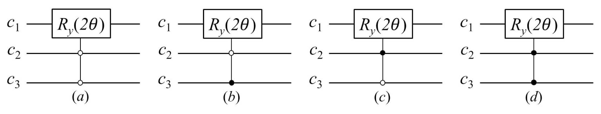
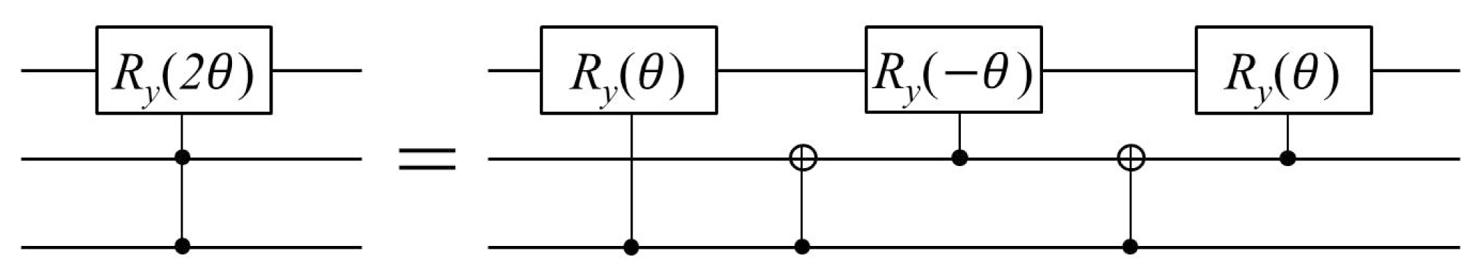
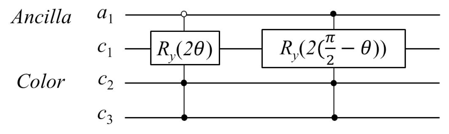
3.2. Channel of Interest Operator

The channel of interest (CoI) operator is shifting the grayscale value of the interested color channel (R, G, B or α channel), which is defined as:
C o I X = U X I 2 n , X R , G , B , α .
The CoIX operator is realized by using UX = C2Ry(2θ) gate, where θ is the shifting parameter (or shifting angle). The calculation produces the result I ( n ) m c X of the application of CoIX on |I(n)mc〉, given as:
I ( n ) m c X = C o I X ( I ( θ ) m c ) = ( U X I 2 n ) ( 1 2 n + 1 i = 0 2 2 n - 1 C R G B α i i ) = 1 2 n + 1 i = 0 2 2 n - 1 C R G B α X i i ,
where the C R G B α i state carries the RGB color information defined in Equation (25); C R G B α X i is the new color state after applying CoIX operator, shown as:
C R G B α R i = cos ( θ R i - θ ) 000 + cos  θ G i 001 + cos  θ B i 010 + cos  θ α i 011 + sin ( θ R i - θ ) 100 + sin  θ G i 101 + sin  θ B i 110 + sin  θ α i 111 ,
C R G B α G i = cos  θ R i 000 + cos ( θ G i - θ ) 001 + cos  θ B i 010 + cos  θ α i 011 + sin  θ R i 100 + sin ( θ G i - θ ) 101 + sin  θ B i 110 + sin  θ α i 111 ,
C R G B α B i = cos  θ R i 000 + cos  θ G i 001 + cos ( θ B i - θ ) 010 + cos  θ α i 011 + sin  θ R i 100 + sin  θ G i 101 + sin ( θ B i - θ ) 110 + sin  θ α i 111 ,
C R G B α α i = cos  θ R i 000 + cos  θ G i 001 + cos  θ B i 010 + cos ( θ α i - θ ) 011 + sin  θ R i 100 + sin  θ G i 101 + sin  θ B i 110 + sin ( θ α i - θ ) 111 .
The quantum image I ( n ) m c X has all of its colors coming from the original image |I(n)mc〉 by shifting the θ angle on the R, G, B or α channel. The quantum circuits of UX (UR, UG, UB and Uα) are C2Ry(2θ) gates and are shown in Figure 9, and the C2Ry(2θ) can be constructed from elementary gates (controlled rotation and CNOT gates), as shown in Figure 10.

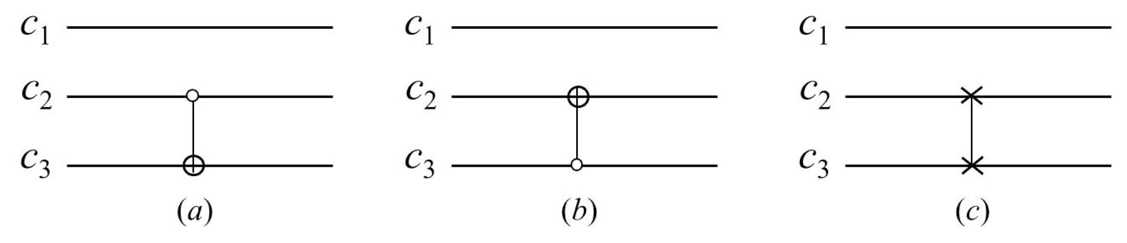
3.3. Channel Swapping Operator

The channel swapping (CS) operator is used to swap the grayscale values between two channels (R and G, R and B; or G and B channels), which is defined as:
C S Y = I U Y I 2 n , Y { R G , R B , G B } .
The CSY operator is completed by means of the CNOT gate or SWAP gate on c2 and c3 color qubits. The calculation produces the result I ( n ) m c Y of the application of CSY on |I(n)mc〉, given as:
I ( n ) m c Y = C S Y ( I ( n ) m c ) = ( I U Y I 2 n ) ( 1 2 n + 1 i = 0 2 2 n - 1 C R G B α i i ) = 1 2 n + 1 i = 0 2 2 n - 1 C R G B α Y i i ,
where C R G B α Y i is the new color state after applying CSY operator, presented as:
C R G B α R G i = cos  θ G i 000 + cos  θ R i 001 + cos  θ B i 010 + cos  θ α i 011 + sin  θ G i 100 + sin  θ R i 101 + sin  θ B i 110 + sin  θ α i 111 ,
C R G B α R B i = cos  θ B i 000 + cos  θ G i 001 + cos  θ R i 010 + cos  θ α i 011 + sin  θ B i 100 + sin  θ G i 101 + sin  θ R i 110 + sin  θ α i 111 ,
C R G B α G B i = cos  θ R i 000 + cos  θ B i 001 + cos  θ G i 010 + cos  θ α i 011 + sin  θ R i 100 + sin  θ B i 101 + sin  θ G i 110 + sin  θ α i 111 .
The quantum image I ( n ) m c Y is obtained from the original image |I(n)mc〉 by applying the CSY operator, and specifically, quantum circuits of UY (URG, URB and UGB) are shown in Figure 11. From Figure 12, at most, three quantum basic gates are utilized to build the CS operator.

3.4. The α Blending Operator

The α blending (α B) operator is used to blend an image A with a background image B to create the appearance of partial or full transparency, which is defined as:
α B A B = U A B I 2 n .
It is widely used in image matte, image rendering and watermarking in the classical image processing field. In this subsection, the circuit to realize this operation on a quantum computer is designed. Assume that images A and B are two same-sized MCQI quantum images with four components (R, G, B and α), where A is the image to be blended and B is the background image. In order to encode the two images in the MCQI quantum states, one ancilla qubit is used to accompany with the MCQI qubits (three color qubits and 2n position qubits for 2n × 2n image), as shown in Figure 13, where C A i and C B i are the color states of images A and B, respectively, which are defined as:
C A i = cos  θ A R i 000 + cos  θ A G i 001 + cos  θ A B i 010 + cos  θ A α i 011 + sin  θ A R i 100 + sin  θ A G i 101 + sin  θ A B i 110 + sin  θ A α i 111 ,
C B i = cos  θ B R i 000 + cos  θ B G i 001 + cos  θ B B i 010 + cos  θ B α i 011 + sin  θ B R i 100 + sin  θ B G i 101 + sin  θ B B i 110 + sin  θ B α i 111 ,
where the θAX and θBX (XR, G,B, α) are angles encoding the color information of images A and B, respectively. Because, before blending, the two images are totally opaque, the initial value of θ A α i and θ B α i is zero. After storing the two images concurrently, two C3-rotation gates are applied on a1 and color (c1, c2, c3) qubits, where the control operations are on a1, c2, c3 and the rotation is on c1 qubits. The computation procedure is shown as:
I α B = α B A B I A B ( θ ) m c = 1 2 n + 3 2 i = 0 2 n - 1 U A B ( 0 C A i + 1 C B i ) I 2 n i = 1 2 n + 3 2 i = 0 2 n - 1 ( 0 C A i + 1 C B i ) i ,
where:
C A i = cos  θ A R i 000 + cos  θ A G i 001 + cos  θ A B i 010 + cos ( θ A α i - θ ) 011 + sin  θ A R i 100 + sin  θ A G i 101 + sin  θ A B i 110 + sin ( θ A α i - θ ) 111 ,
C B i = cos  θ B R i 000 + cos  θ B G i 001 + cos  θ B B i 010 + cos ( θ B α i + θ - π 2 ) 011 + sin  θ B R i 100 + sin  θ B G i 101 + sin  θ B B i 110 + sin ( θ B α i + θ - π 2 ) 111 .
The quantum circuit of UAB is shown in Figure 11.

4. Parallel Comparison of Multiple Pairs of FRQI Quantum Images

A method to compare multiple pairs of quantum images in parallel [36,37] is introduced in this section, where the similarities of the images are estimated in accordance with the probability distributions of the readouts from quantum measurements. The method by means of a single Hadamard gate with control-conditions to transform the entire information of the quantum images in a strip offers a significant speed-up in comparison to performing the same task on traditional computing devices.

4.1. Representation of Strip Encoding Multiple FRQI Images

A dextrous property of the strip representation [12,44] to encode 2m-ending FRQI quantum images lies in its ability to utilize the parallelism inherent to quantum computation in order to transform multiple images using very few quantum resources. The definition of the strip and its properties are introduced in this subsection.

Definition 1

A strip, |S(m, n)〉, is an array comprising 2m FRQI quantum images, which is defined by:
S ( m , n ) = 1 2 m / 2 s = 0 2 2 m - 1 I s ( n ) s ,
where:
I s ( n ) = 1 2 n i = 0 2 2 n - 1 c s , i i ,
c s , i = cos  θ s , i 0 + sin  θ s , i 1 ,
θ s , i [ 0 , π 2 ] , i = 1 , 2 , , 2 2 n - 1 , s = 1 , 2 , , 2 m - 1 ,
where |sis the position of each image in the strip, m is the number of qubits needed to encode the images being compared, |Is(n)〉 is a FRQI quantum image as defined in Equation (7) at position |s, |cs,iand |iencode the information about the colors and their corresponding positions in the image |Is(n)〉.
The state |S(m, n)〉 is normalized, which can be confirmed by:
S ( m , n ) = 1 2 m / 2 s = 0 2 m - 1 I s ( n ) 2 = 1 2 m / 2 + n s = 0 2 m - 1 i = 0 2 2 n - 1 ( cos 2 θ s , i + sin 2 θ s , i ) = 1.
As seen in Figure 14, the size of a strip in the representation captures the input state of the strip comprising 2m quantum images. Each image in the strip is an FRQI state, while the combination of such states in the strip is best represented as a multiple FRQI or simply the mFRQI state. The mFRQI state can represent 2m quantum images using only m + 2n + 1 qubits, since all of the images are of the same size in this strip.
The 2m-ending FRQI quantum images encoded in a strip can be horizontally (or vertically) oriented [12,36]. The latter case, the vertically-oriented strip is implied in the ensuing discussion. Control-conditions on strip wires could control the image that is being processed, combined with the control-conditions from the position |y〉|x〉 to the color wire; every pixel in this strip can be accessed.

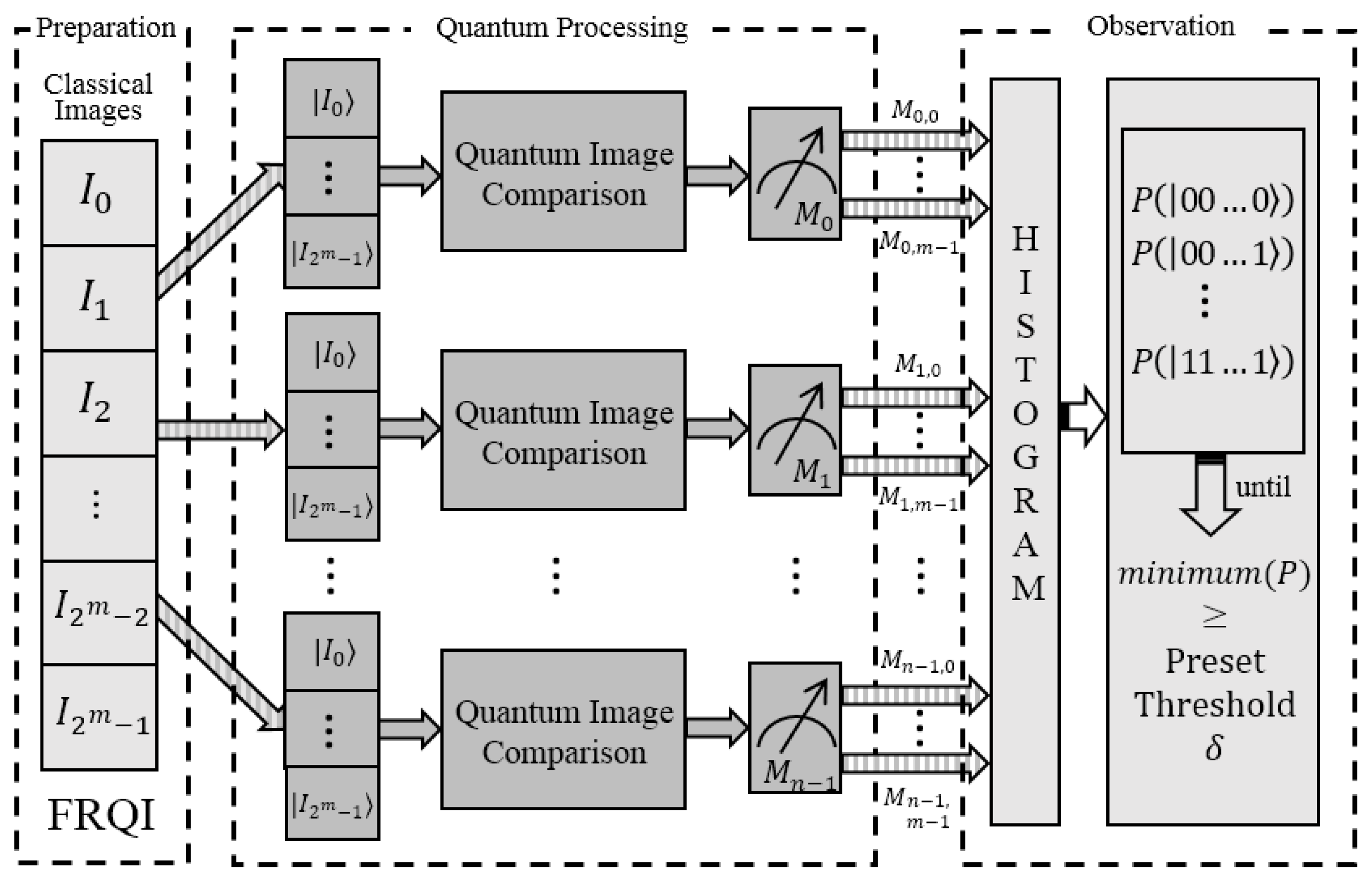
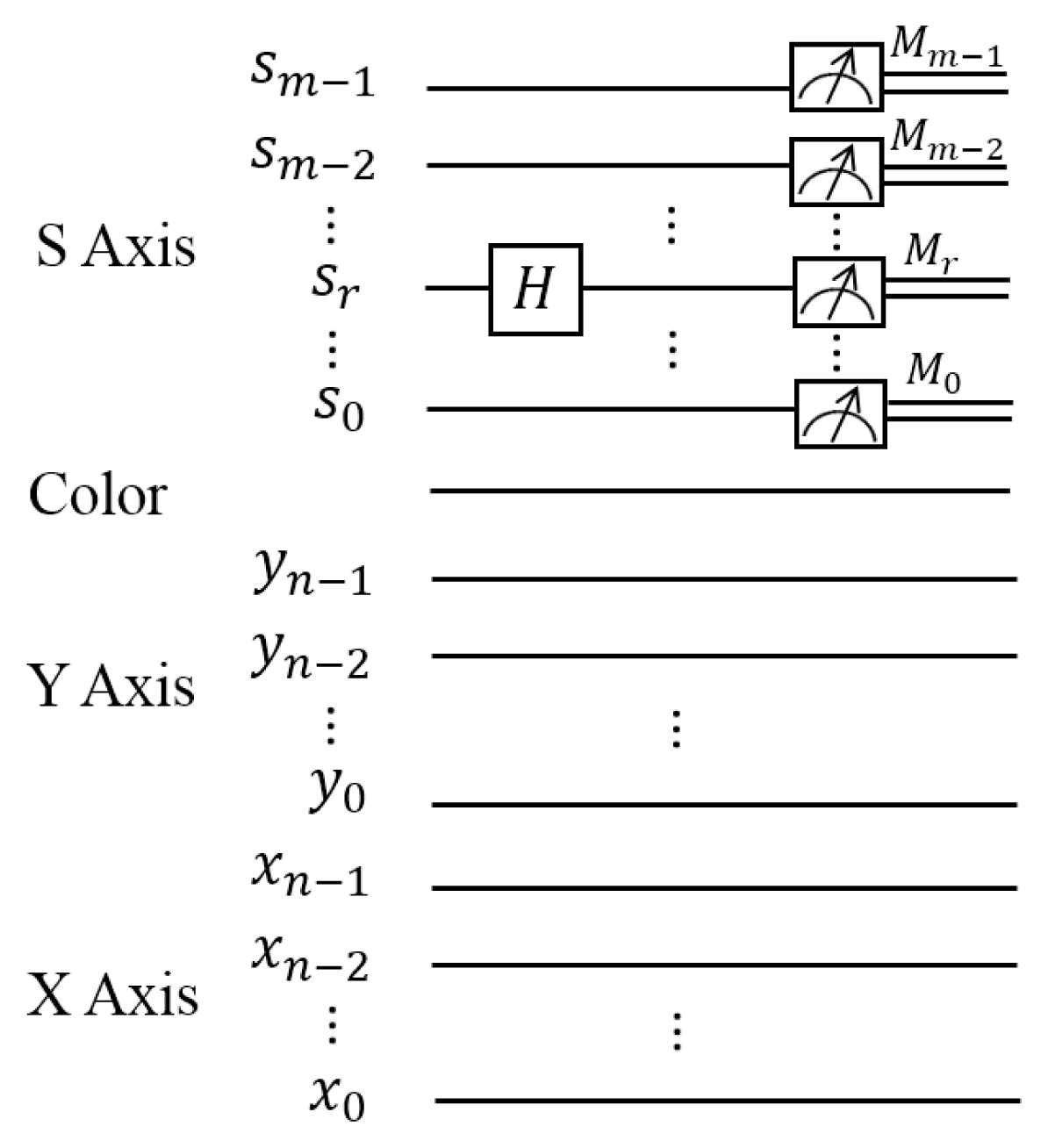
4.2. Scheme to Compare Images in Parallel on Quantum Computers

The scheme to compare quantum images on quantum computers, together with several momentous definitions as the basis of the ensuing discussions, is presented in this subsection. It starts with the introduction of comparison for two quantum images. The comparison of two FRQI quantum images |Ik(n)〉 and |It(n)〉,
I k ( n ) = 1 2 n i = 0 2 2 n - 1 ( cos  θ k , i 0 + sin  θ k , i 1 ) i ,
I t ( n ) = 1 2 n i = 0 2 2 n - 1 ( cos  θ t , i 0 + sin  θ t , i 1 ) i ,
is that they obtain the similarity, which is in the interval from zero to one, between them through the quantum operations. In addition, given a strip comprising 2m quantum images, parallel comparison of quantum images retrieves the similarities between 2m − 1 pairs of images in the strip simultaneously.

Definition 2

The difference between the ith pixels of two FRQI quantum images |Ik(n)〉 and |It(n)〉, as defined in Equations (49) and (50), is given by:
σ k , t i = θ k , i - θ t , i , σ k , t i [ 0 , π / 2 ] ,
where θk,i and θt,i represent the color information at position i of the two images, respectively.

Definition 3

The similarity between two FRQI quantum images |Ik(n)〉 and |It(n)〉, as defined in Equations (49) and (50), is a function of pixel difference σk,t at every position of the image given by:
s i m ( I k , I t ) = f ( σ k , t 0 , σ k , t 1 , , σ k , t 2 2 n - 1 ) ,
where sim(|Ik〉, |It〉) ∈ [0, 1].
The representation of strip, which was introduced in Section 4.1, facilitates smooth comparison of multiple quantum images of equal size. The scheme to compare quantum images in parallel consists of three steps, as detailed in Figure 15. These steps are outlined in this subsection.
  • Preparation of the strip comprising 2m quantum images
    The quantum images are prepared into FRQI states using their classical versions images. The color information, as well as the corresponding positions of every point in the classical version are integrated into the quantum state, and the 2m quantum images being compared are combined to form a vertically-oriented strip. The routine involved in preparing FRQI quantum images and its extension to encode multiple FRQI quantum images as a single register, called the strip, are discussed thoroughly in [12,21,36].
  • Comparison of quantum images through quantum operations
    The strip as prepared in the preceding period is transformed using geometric transformations [29] on all of the images in the strip. This transformation step combines with measurement operations that follow it to convert the quantum information into the classical form as probability distributions. Since measurements are known to destroy the superposition state in quantum systems [15], the strip has to be prepared n (n > 1) times in order to compare the similarity between two FRQI quantum images (in parallel).
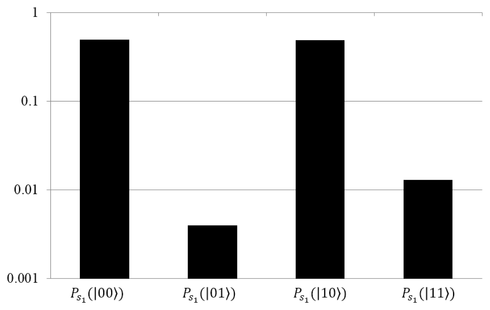
  • Observation of readouts from quantum measurements
    The readouts from the n quantum measurements build up a histogram that implicitly reflects the probability distributions. Extracting and analyzing these distributions gives information about the similarity values between the quantum images being compared. The strip preparation will be continued until min(P(|sm−1, . . . , s0〉)) ≥ δ, where min(P(|sm−1, . . . , s0〉)) is the minimum of the probabilities of the readouts from the experiments and δ ∈ [0, 1] is a pre-set threshold, which can be read as the reasonable estimation for the similarity between two quantum images being compared.
The comparison of quantum images in this scheme is especially specified in the ensuing subsections, which are the parallel comparison of multiple pairs of images and the comparison of sub-blocks from two arbitrary images in a strip.

4.3. A Parallel Comparison of Multiple Pairs of Images in a Strip

The parallel computation on quantum computer leads us to find a way of comparing many pairs of images in parallel. The proposal of the strip comprising 2m images as defined in Definition 1 provides us a crucial condition to make it possible, because the operation on the strip wires can transform the information in every image simultaneously. The generalized circuit structure of comparing 2m − 1 pairs of quantum images in parallel is presented in Figure 16. By applying a Hadamard operation on the rth strip wire in the circuit, sr, the mathematical expressions between the two images being compared are realized. The final step in the procedure consists of m measurements from which the similarity can be retrieved in each pair of images.
Due to the representation of the strip and the property of Hadamard operation, only the specified pairs of images in the strip can be compared, which is the kth image, |Ik〉, and the (k + 2r) − th image, |Ik+2r 〉 (r is the index of sr in the circuit). Therefore, the mFRQI state of the strip when 2m − 1 pairs of images are compared is:
S ( m , n ) = 1 2 m / 2 s = 0 2 m - 1 I s ( n ) s = 1 2 m / 2 z = 1 2 m - r - 1 k = g ( z ) 1 2 g ( 2 z ) - 1 ( I k k + I k + 2 r k + 2 r ) ,
g ( z ) = ( z - 1 ) 2 r + 1 ,
where m ≥ 2, |s〉 = |sm−1, . . . , sr+1, sr, sr−1, . . . , s0〉, sr ∈ {0, 1}.
Applying the Hadamard gate on the strip wire sr (expressed by Hr|S(m, n)〉) transforms the state of the strip into:
H r S ( m , n ) = 1 2 m / 2 s = 0 2 m - 1 I s ( n ) s m - 1 , , s r + 1 H s r s r - 1 , , s 0 = 1 2 m / 2 z = 1 2 m - r - 1 k = g ( z ) 1 2 g ( 2 z ) - 1 I k ( n ) s m - 1 , , s r + 1 H 0 s r - 1 , , s 0 + 1 2 m / 2 z = 1 2 m - r - 1 k = g ( z ) 1 2 g ( 2 z ) - 1 I k + 2 r ( n ) s m - 1 , , s r + 1 H 1 s r - 1 , , s 0 = 1 2 ( m + 1 ) / 2 z = 1 2 m - r - 1 k = g ( z ) 1 2 g ( 2 z ) - 1 ( I k ( n ) + I k + 2 r ( n ) ) s m - 1 , , s r + 1 , 0 , s r - 1 , , s 0 + 1 2 ( m + 1 ) / 2 z = 1 2 m - r - 1 k = g ( z ) 1 2 g ( 2 z ) - 1 ( I k ( n ) - I k + 2 r ( n ) ) s m - 1 , , s r + 1 , 1 , s r - 1 , , s 0 ,
where:
I k ( n ) ± I k + 2 r ( n ) = 1 2 n i = 0 2 2 n - 1 ( c k , i ± c k + 2 r , i ) i = 1 2 n i = 0 2 2 n - 1 [ ( cos  θ k , i ± cos  θ k + 2 r , i ) 0 + ( sin  θ k , i ± sin  θ k + 2 r , i ) 1 ] i .
The probability of the readouts from the m measurements is given by:
P s r ( s m - 1 , , s r + 1 , 0 , s r - 1 , , s 0 ) = 1 2 m + 2 n z = 1 2 m - r - 1 k = g ( z ) 1 2 g ( 2 z ) - 1 i = 0 2 2 n - 1 1 + cos ( θ k - θ k + 2 r ) = 1 2 + 1 2 m + 2 n z = 1 2 m - r - 1 k = g ( z ) 1 2 g ( 2 z ) - 1 i = 0 2 2 n - 1 cos  σ k , k + 2 r i .
In the same way, that of state |sm−1, . . . , sr+1, 1, sr−1, . . . , s0〉 on sr is given by:
P s r ( s m - 1 , , s r + 1 , 1 , s r - 1 , , s 0 ) = 1 2 - 1 2 m + 2 n z = 1 2 m - r - 1 k = g ( z ) 1 2 g ( 2 z ) - 1 i = 0 2 2 n - 1 cos  σ k , k + 2 r i .
From this, it becomes evident that:
P s r ( s m - 1 , , s r + 1 , 0 , s r - 1 , , s 0 ) + P s r ( s m - 1 , , s r + 1 , 1 , s r - 1 , , s 0 ) = 1.
The states |sm−1, . . . , sr+1, 0, sr−1, . . . , s0〉 and |sm−1, . . . , sr+1, 1, sr−1, . . . , s0〉 represent all of the images that are at the kth and (k + 2r) − th position of the strip, respectively. In order to determine the similarity of every pair of images, the generalized representation of the probability of |Ik+2r (n)〉 in the strip is given by:
P s r ( k + 2 r ) = 1 2 m + 2 n i = 0 2 2 n - 1 1 - cos ( θ k - θ k + 2 r ) = 1 2 m - 1 2 m + 2 n i = 0 2 2 n - 1 cos  σ k + 2 r i .
In addition, the similarity between |Ik(n)〉 and |Ik+2r (n)〉 can be presented as:
s i m ( I k , I k + 2 r ) = 1 - 2 m P s r ( k + 2 r ) = 1 2 2 n i = 0 2 2 n - 1 cos  σ k , k + 2 r i ,
where |Ik〉 and |Ik+2r〉 are the two images being compared in the strip, Psr (|k + 2r〉) is defined in Equation (60) and sim(|Ik〉, |Ik+2r〉) ∈ [0, 1]. The similarity between |Ik〉 and |Ik+2r〉, which are encoded in the strip comprising 2m images, is also determined in accordance with Definition 3, where f ( σ k , t 0 , σ k , t 1 , , σ k , t 2 2 n - 1 ) = 1 2 2 n i = 0 2 2 n - 1 cos  σ k , k + 2 r i.

4.4. Comparison between Two Arbitrary Quantum Images and Sub-Blocks of Them

As mentioned in Section 4.3, the position of the two images being compared, which are the kth and (k + 2r) − th images in the strip (r is the index of sr in the circuit), in a strip is relatively fixed. In order to compare two arbitrary quantum images and/or contents of their sub-blocks from a strip, some geometric transformation and control-conditions are applied to the quantum system. In this subsection, the more complicated cases of quantum image comparison are discussed, such as comparing arbitrary pairs of images, comparing sub-blocks from two images in a strip. The circuit structure for realizing such processes is presented in Figure 17.
The input of this circuit is the mFRQI state, as defined in Equation (44) (expressed by |SI〉 in the circuit); the operation GS that is applied on the strip wires is the geometric operation, which can swap two images in the strip when two arbitrary images are supposed to be compared. A notation “⊘”, to indicate for “0” or “1” control-condition, is adopted throughout the discussion. The additional control-conditions on either of the position axis (Y-axis or X-axis) are necessary in order to confine this Hadamard operation to the required sub-blocks from the images that are being compared. The operation GI is needed when the sub-blocks being compared are at different positions from the two images. The state in the circuit after applying the Hadamard gate on the rth strip wire is transformed into HrGs|SGI 〉, as shown in Figure 17.
The similarity between the sub-blocks from two FRQI quantum images encoded in a strip is:
s i m ( i k , i t k + 2 r ) = 1 - 2 m p q P s r ( k + 2 r ) ,
where |ik〉 and |itk+2r 〉 are the sub-blocks from the two images |Ik〉 and |Itk+2r 〉 in the strip, |Itk+2r 〉 is the image from the position t to k + 2r using the geometric transformation on the strip wires, p is the area of the image |Ik〉 or |Itk+2r 〉, q is the area of the sub-block |ik〉 or |itk+2r 〉 in the two images and Psr (|k +2r〉) is the probability of the readouts in the measurements from the state |k +2r〉, as discussed in Equation (60), sim(|ik〉, |itk+2r 〉) ∈ [0, 1].

4.5. Simulation Experiment to Assess the Similarity of Quantum Images

In the absence of the physical quantum hardware to implement the image comparison, the simulation is carried out using MATLAB based on linear algebra with complex vectors as quantum states and unitary matrices as unitary transforms. A conventional desktop computer (Intel Core i7, 2 Duo 2.80 GHz CPU, 4 GB RAM and 64-bit operating system) is utilized to simulate the experiments. The purpose of this experiment is to realize the comparison between two sub-blocks from two arbitrary images in a strip. As shown in Figure 18, we intend to compare the Lena image in the bottom left of the image in |I0〉 (labeled as i 0 3 ) with the watermarked Lena image in the top right of the image in |I3〉 (labeled as i 3 2 ); and the Man image (labeled as i 1 3 ) with the processed Man image (labeled as i 2 3 ) at the same position in |I1〉 and |I2〉, respectively. The enlarged versions of these four images that are being compared are presented in the bottom row of the Figure 18. For brevity, the four 1, 024 × 1, 024 images are indicated by only their labels |I0〉, |I1〉, |I2〉 and |I3〉 in the strip on the left in the same figure.
The corresponding circuit structure to compare them is presented in Figure 19. There are four steps to accomplish this comparison:
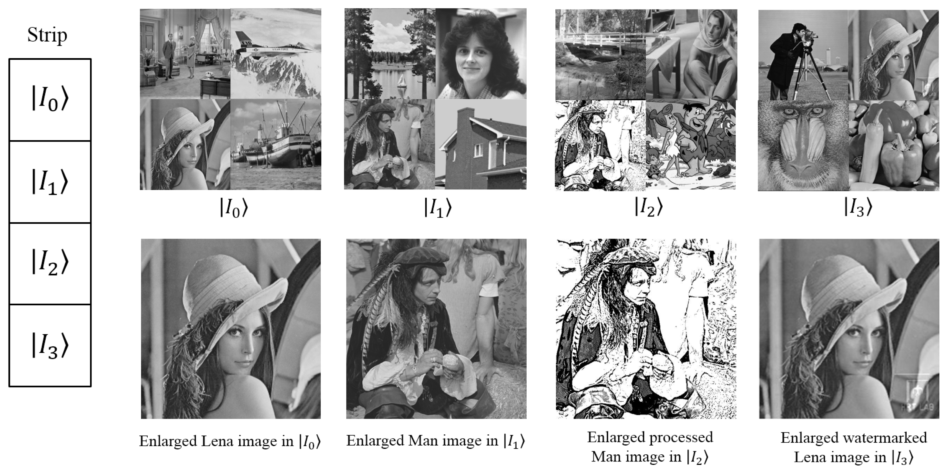
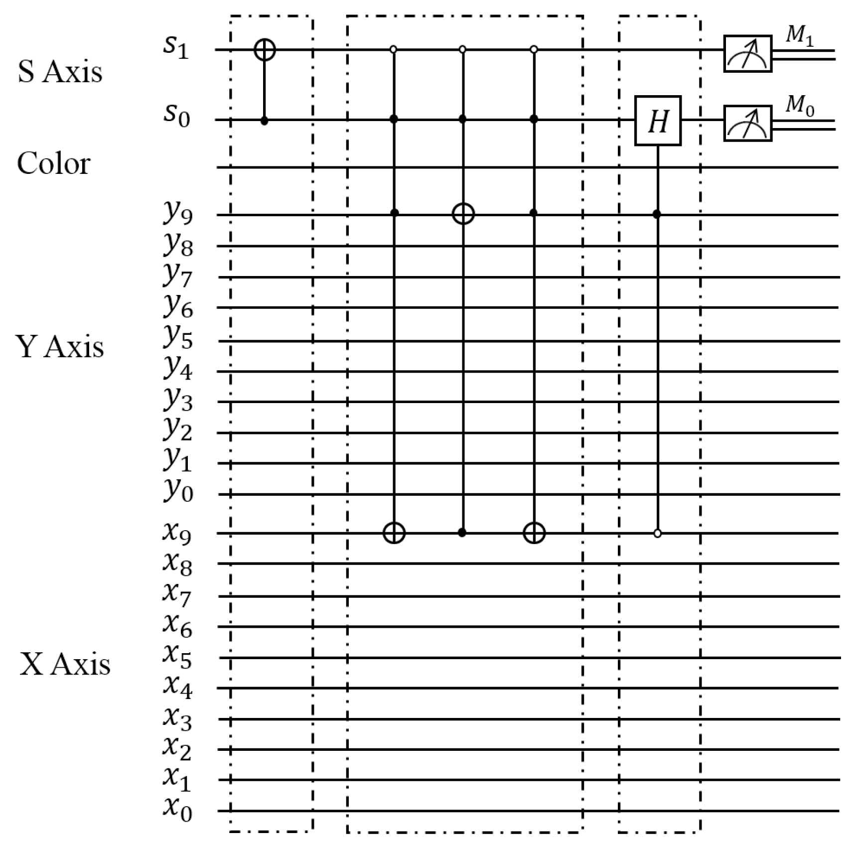
  • Swap the position between |I1〉 and |I3〉 using the C-NOT gate on the strip wires.
  • Swap the position of the watermarked Lena image with baboon in |I3〉.
  • Compare the two Lena images and two “Man” images in parallel by applying the Hadamard gate on s0 with appropriate control-condition operations to confine the operation to the desired sub-blocks.
  • Observe the readouts from the quantum measurements to build up a histogram that can reflect the similarity of the two pairs of images.
The probabilities of getting the readouts (in log scale) on the strip wires in the measurements are presented in Figure 20, and the similarities among different pairs of images being compared are presented in the Table 1, from which the similarity between the original Lena image and the watermarked Lena image is obtained.
To conclude, the proposed quantum image comparison method is proven to require less computational resources and, hence, offers a significant speed-up in comparison to performing the same task on traditional computing devices. The proposal provides a first step towards image database search on quantum computers, whereby an image could be retrieved as a search result from a database based on the extent of its similarity in comparison with the particular reference image. To realize such a search procedure, a reconstitution of the quantum system by adding some additional wires to the circuit in order to represent the images in the database and the reference images together might be necessary. Then, the comparison is performed between the images to get the best result as the image with highest similarity value to the reference image. The detailed image searching method will be discussed in Section 5.

5. Quantum Image Searching Based on Probability Distributions

Inspired by the utility and importance of image searching on conventional computers in today’s world, research on quantum image searching appears to be an indispensable field in quantum image processing [45,46]. In order to improve the limitation of the traditional searching, e.g., only text-based and time consuming, the quantum image searching on the strength of the content of the images can be executed in parallel to realize more efficient computation. Utilizing the FRQI representation and the method of estimating the similarity value between two FRQI quantum images in Sections 2 and 4, a quantum image searching method [38] is presented, such that an image could be retrieved as a search result from a database based on the extent of its similarity in comparison with the particular test image.

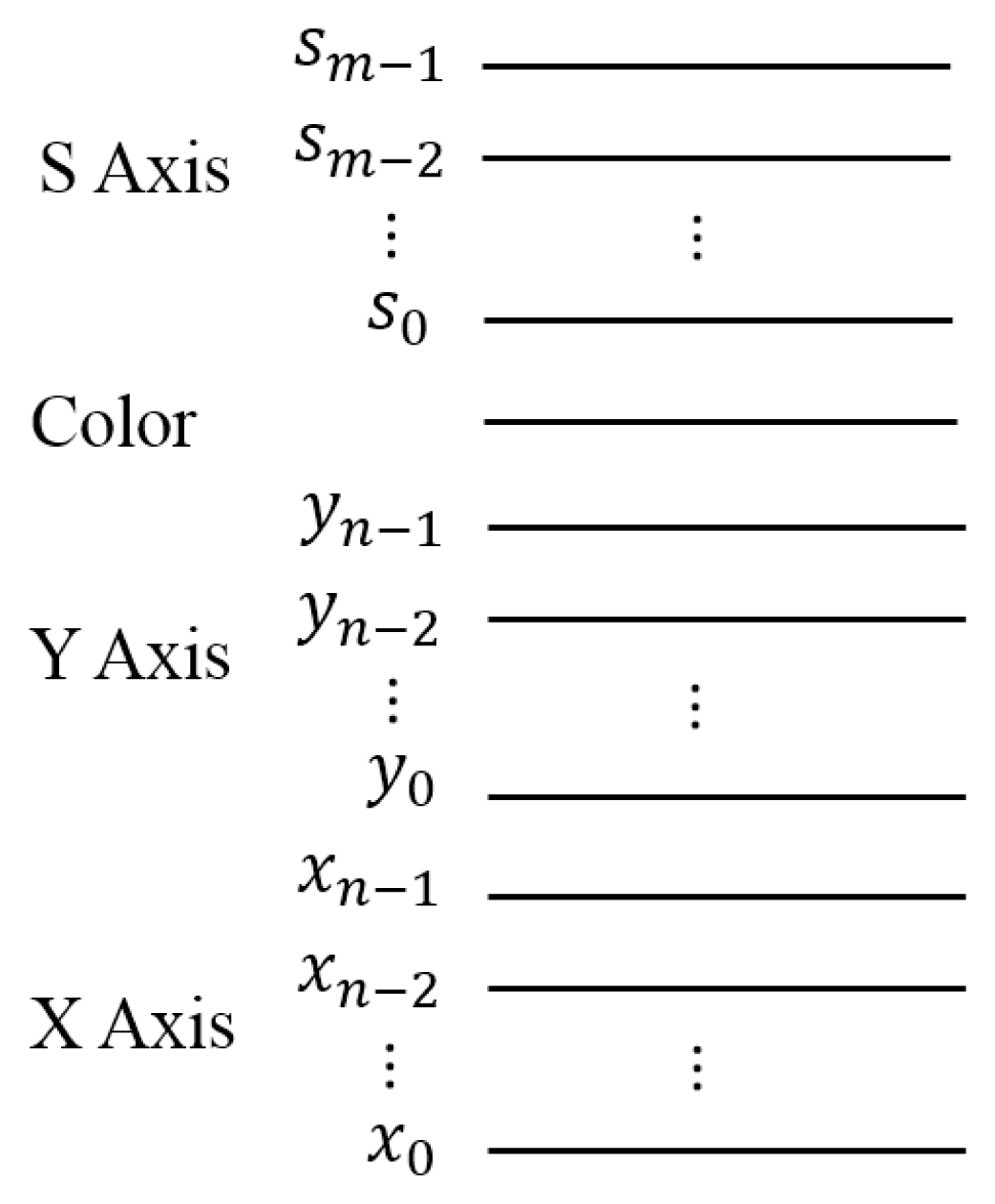
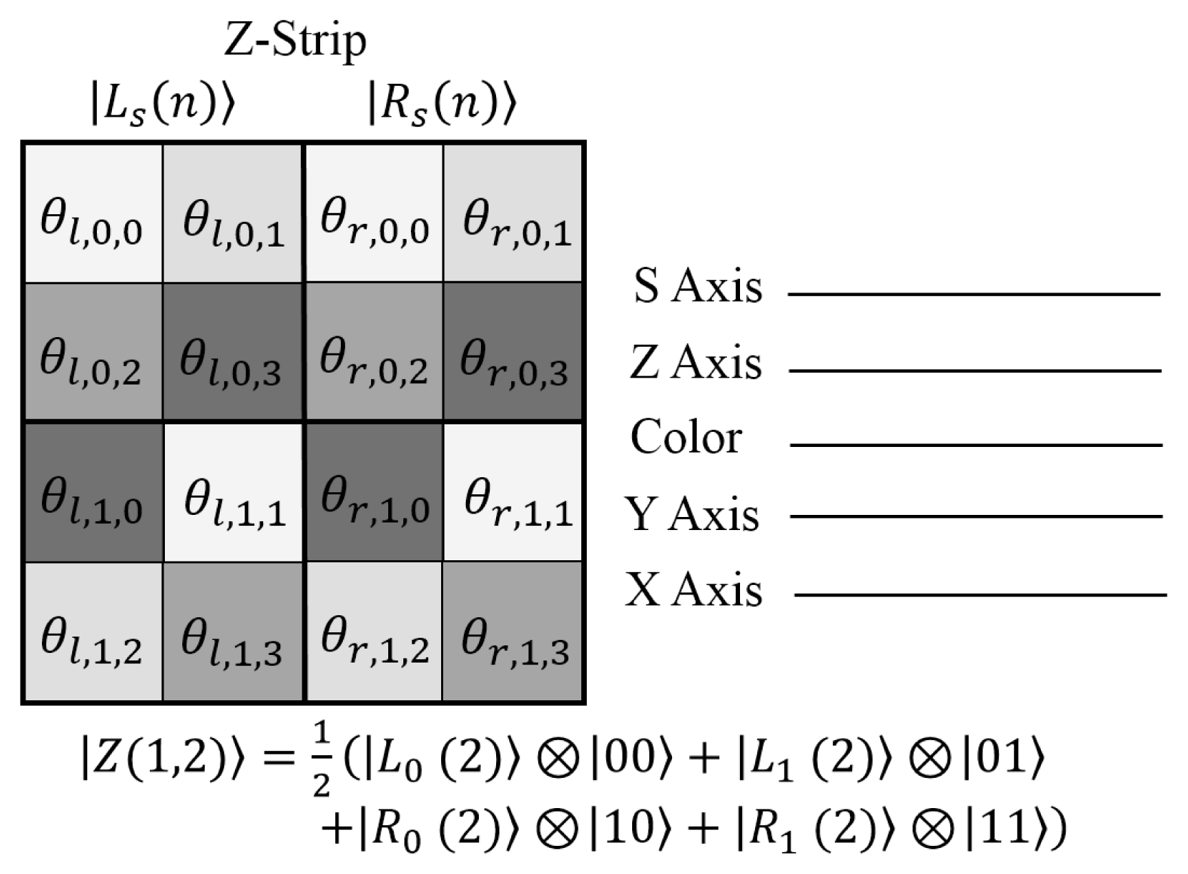
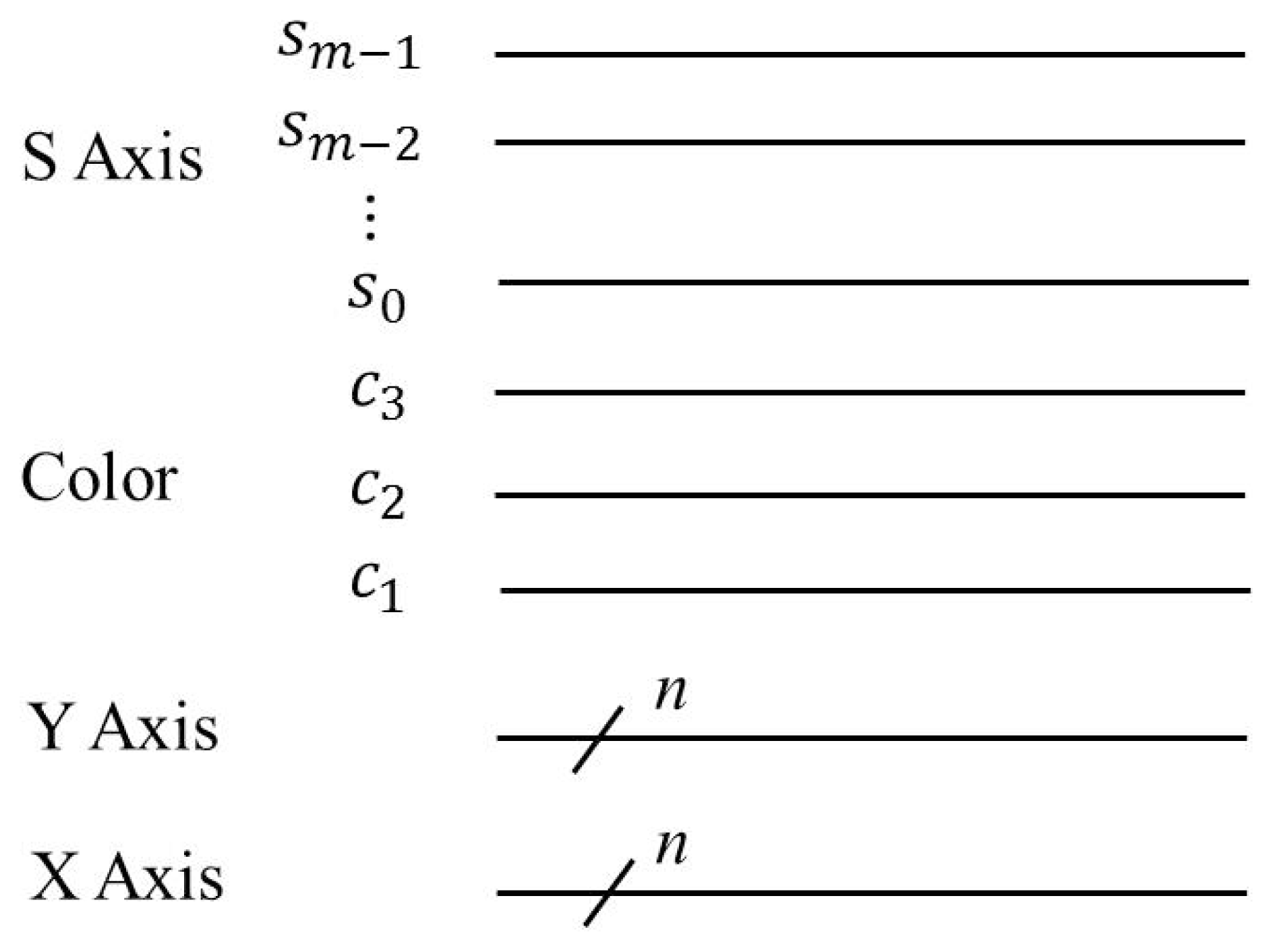
5.1. Representation of Z-Strip to Indicate Multiple FRQI Quantum Images

For the quantum image processing, a good deal of operations are done by relying on the corresponding processing in classical images, as [21,47]. The flexible representation for quantum images, FRQI [21,26], which is similar to the pixel representation for images on conventional computers, encodes the fundamental information (the colors and the corresponding positions) of an image and, in addition, integrates them into a quantum state, as presented in Equations (7) to (9).

Definition 4

A Z-strip, |Z(m, n)〉, is a horizontal combination of two strips [12], which are located on the left and right side, respectively, which is defined by:
Z ( m , n ) = 1 2 ( m + 1 ) / 2 s = 0 2 m - 1 ( L s ( n ) 0 + R s ( n ) 1 ) s ,
where |Ls(n)〉 and |Rs(n)〉 are FRQI quantum images as defined in Equations (64) and (65),
L s ( n ) = 1 2 n i = 0 2 2 n - 1 c l , s , i i ,
R s ( n ) = 1 2 n i = 0 2 2 n - 1 c r , s , i i ,
c l , s , i = cos l , s , i 0 + sin l , s , i 1 ,
c r , s , i = cos r , s , i 0 + sin r , s , i 1 ,
θ l , s , i , θ r , s , i [ 0 , π 2 ] ,
i = 0 , 1 , , 2 2 n - 1 , s = 0 , 1 , , 2 m - 1.
As seen in Figure 21, the size of a Z-strip in the representation captures the input state comprising 2m+1 quantum images. The Z-axis differentiates the strip that is located on the left and the right position. Each image in the Z-strip is an FRQI state, while the combination of such states in the Z-strip is best represented as a zFRQI state.
The zFRQI state represents 2m+1 quantum images using only m + 2n + 2 qubits, since all of the images are of the same size on this Z-strip. The notation, “○” for “0” or “●” for “1” control-condition on the Z-axis or S-axis, is sufficient to specify any quantum image in the Z-strip. An example that has two 2×2 images on both the left and right side of the Z-strip, respectively, including its circuit structure and zFRQI state, is shown in Figure 22.

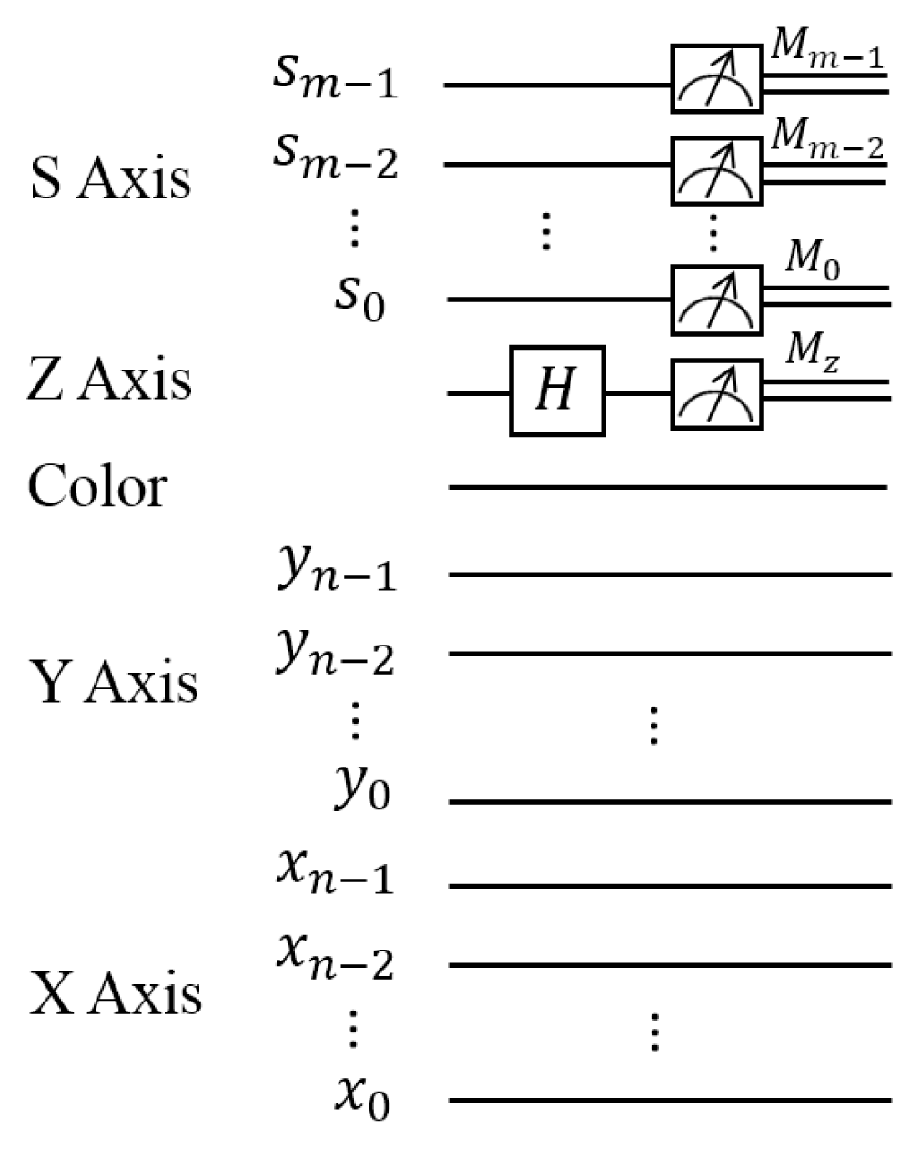
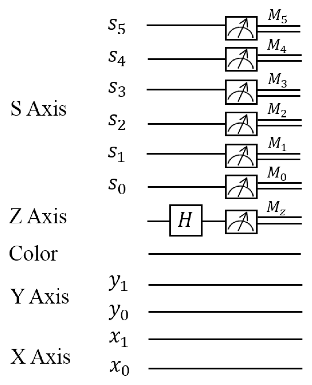
5.2. Image Searching on Quantum Mechanical Systems

A first step towards realizing the quantum image searching would be to propose a scheme, so as to evaluate the extent to which two or more images are similar to one another. The parallel computation on quantum computers allows us to find a way of comparing many pairs of images in parallel. The proposal of the Z-strip comprising 2m + 1 images in Definition 4 provides us a crucial condition to make the parallel comparison of quantum images possible, because the operation on the strip wires can transform the information in every image simultaneously. The generalized circuit structure of comparing 2m pairs of FRQI quantum images in Z-strip in parallel is presented in Figure 23.
The input of this circuit is the zFRQI state, as defined in Equation (63); a Hadamard gate is applied on the Z-axis to obtain the new mathematical expressions between the two images being compared. The final step in the circuit consists of m + 1 measurements, from which the similarity can be retrieved in each pair of images. When n experiments are performed, the measurement results on the Z-axis follow a binomial distribution. The probability of obtaining k readouts of one in n experiments is described by the probability mass function,
P r ( X = k ) = C n k p k ( 1 - p ) n - k ,
where X is the incident that the result of measurement is one and p is the probability of one when the results on the Z-axis are measured, k = 0, 1, …, n.
Meanwhile, the measurement results on the S-axis, sm−1 · · · sr · · · s0, sr ∈ {0, 1}, give the position of probabilities of the measurements on the Z-axis. According to the readouts on both the measurements, the similarity between each pair of images on the Z-strip can be assessed, from which the quantum image searching can be realized.
As presented in Figure 23, after applying the Hadamard gate on the strip wire, the state of quantum system is transformed to a new state, as given in Equations (71) and (72).
H z Z ( m , n ) = 1 2 m / 2 s = 0 2 m - 1 ( L s ( n ) ( 0 + 1 ) 2 + R s ( n ) ( 0 - 1 ) 2 ) s = 1 2 ( m + 1 ) / 2 s = 0 2 m - 1 [ ( L s ( n ) + R s ( n ) ) 0 + ( L s ( n ) - R s ( n ) ) 1 ] s ,
where:
L s ( n ) ± R s ( n ) = 1 2 n i = 0 2 2 n - 1 [ ( cos  θ l , s , i + cos  θ r , s , i ) 0 ± ( sin  θ l , s , i + sin  θ r , s , i ) 1 ] i .
Apparently, the measurement results relies on the differences between |Ls(n)〉 and |Rs(n)〉. Therefore, the probability of state |0〉 on the Z-axis at position |sm−1, sm−2, · · ·, s0〉 is shown by:
P s ( 0 ) = 1 2 + 2 2 2 n + 1 i = 0 2 2 n - 1 cos ( θ l , s , i - θ r , s , i ) .
In the same manner, that of state |1〉 on the same wire is:
P s ( 1 ) = 1 2 - 1 2 2 n + 1 i = 0 2 2 n - 1 cos ( θ l , s , i - θ r , s , i ) .

Definition 5

Pixel difference in position i, σs,i, is defined by:
σ s , i = θ l , s , i - θ r , s , i , σ s , i [ 0 , π 2 ] ,
where θl,s,i and θr,s,i encode the color information at position i of the two images, which are at the sth position of the Z-strip, respectively.
It is apparent that, arising from Equations (74) and (75), the pixel difference σs,i is decided by the probability of obtaining readout of one from the Z-axis, Ps(|1〉), in the measurement. In addition, the similarity between the two images at the same position of Z-strip is given by:
s i m ( L s ( n ) , R s ( n ) ) = 1 - 2 P s ( 1 ) = 1 2 2 n i = 0 2 2 n - 1 cos  σ s , i ,
where |Ls(n)〉 and |Rs(n)〉 are the two images being compared, Ps(|1〉) is defined in Equation (74) and sim(|Ls(n)〉, |Rs(n)〉) ∈ [0, 1].
Based on the comparison method and the probability distributions introduced above, the scheme to accomplish the image searching on quantum mechanical systems is presented in Figure 24. The quantum images are prepared from the classical images using FRQI representation [12,21,33,37]. The color information and the corresponding positions of every point in the classical image is integrated into the quantum state, and the 2m+1 quantum images being compared are combined as a Z-strip. Because of the superposition property of quantum computation, such work can be realized using only a few quantum resources. However, the Z-strip is prepared n(n > 1) times to compare the similarity between two quantum images in parallel, since a measurement would collapse the superposition state in the quantum system [15]. By analyzing the distributions, the similarity values between the quantum images being compared are provided, so that the image with the highest similarity to the particular test image could be retrieved as a result from the database.
The operation to search image on quantum mechanical systems is accomplished by utilizing only a single Hadamard gate and several measurements. Such an image searching scheme, however, can only be realized by comparing one pair of images at a time on a classical computer. Hence, the proposed method offers a significant speed-up compared to how it is performed using classical computing resources.

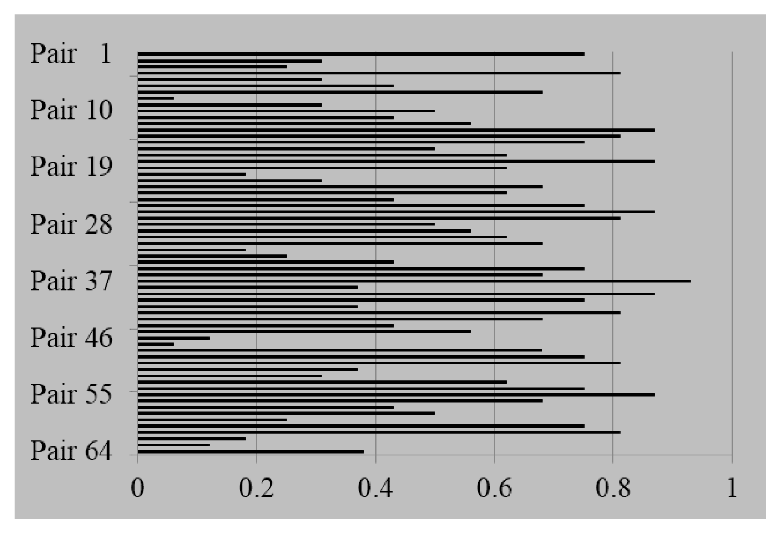
5.3. Simulation Experiments to Search Quantum Images from Database

The experiment is simulated using the same experiment environment with Section 4. The purpose of this experiment is to search the image from a database that has the highest similarity with the test image. An original database that includes sixty-four 4×4 binary image data is used; then the Z-strip comprised of |D0(2)〉, |D1(2)〉, …, |D63(2)〉 and sixty-four |T(2)〉s is constituted as shown in Figure 25.
The corresponding circuit structure to realize such an image searching is presented in Figure 26. There are three steps to achieve this comparison:
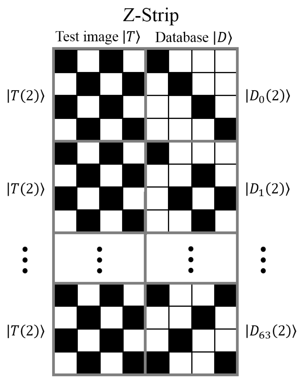
  • The test images |T(2)〉 is prepared from the classical version using FRQI representation and integrated with a Z-strip state with the images |D〉 in the database.
  • A Hadamard operation is applied on the Z-axis in order to compare the test image |T(2)〉 with |D0(2)〉, |D1(2)〉, … and |D63(2)〉.
  • The measurements that convert the quantum information to the classical form are used on the S-axis and Z-axis to distribute the readouts from which the histogram is built to reflect the similarity of the sixty-four pairs of images.
The circuit is comprised of 12 qubits, of which six are adopted to address positions of the image, one qubit is reserved for storing the information about the colors and the remaining qubits are prepared for representing the Z-strip wire on which the Hadamard gate and measurement MZ are applied. A simulation of a single Hadamard gate and seven measurement operations are used to obtain the similarities for these 64 pairs of images based on the probabilities of getting the readouts on the Z-axis and S-axis in the measurements, as shown in the Figure 27. From the histogram, the image |D37(2)〉, which manifests the highest similarity value of 0.93 to the test image |T(2)〉, is retrieved as the searching result. It is testified by that the quantum image searching is based on the pixel difference between the test image and the images in the database.
To summarize, a quantum image searching method is proposed in this section based on the probability distributions of the readouts from the quantum measurements. It is achieved by using low computational resources, which are only a single Hadamard gate combined with m + 1 quantum measurement operations. In addition, the method will be applied for designing a search engine on such quantum computing devices, such that the image in the database is retrieved based on its similarity to the test image. Most of the search engines recently have only been based on the text to realize the searching [48]. Even some searching is developed based on the content of the images. It is, however, usually time consuming. This work, which realizes the searching based on the content of the images and is executed in parallel, proposes a basic step for the quantum image searching, especially when a database comprised of a huge amount of data is confronted.

6. Watermarking and Recovery Strategies for FRQI and MCQI Quantum Images

In this section, four kinds of different watermarking strategies that are based on the FRQI representation and its color information extension, MCQI, representation are reviewed. They include the pioneering keyless and blind watermarking and authentication strategy (WaQI) [33], its two-tier grayscale version (GQaQI) [34], quantum Fourier transform-based watermark strategy [49] and the duple watermarking strategy for MCQI quantum images [50].

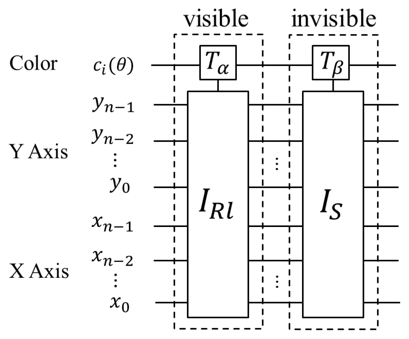
6.1. Watermarking of Quantum Images Based on Restricted Geometric Transformations

A secure, keyless and blind watermarking and authentication strategy for images on quantum computers, WaQI, was first proposed in [35], enhanced in [33] and later reviewed in [51]. This strategy is credited with pioneering research in what is today emerging as quantum image watermarking. Prior to the WaQI protocol, most of what the literature attributed to quantum watermarking was merely the secret exchange of information between cryptography’s famous couple, Alice and Bob [15].
The geometric transformations on the contents of an image are considered undesirable in conventional digital watermarking techniques. In contrast with these, the WaQI scheme utilizes the restricted variants of these transformations as the main resources of the watermark embedding and authentication circuits. Similarly, a sizeable number of schemes and protocols, including others based on non-FRQI representations for the quantum images, have benefited from the prime work in the WaQI stratagem [50,52,53].
As mentioned earlier, there is enough literature detailing the WaQI protocol, so we will only review necessary aspects of this strategy. Interested readers are referred to the extensive discussions in [33,35,51]. As noted there, the quantum watermark-embedding procedure has two stages, each of which is further divided into two parts, as shown in Figure 28. The first stage of this procedure is about the accessibility to the various stages by the copyright owners and users of the watermarked images, and the second is that the data type for realizing the watermarked images (whether the data is quantum or classical in nature). The copyright owner has access to both the classical and quantum versions of the image and watermark signal, while the end-users are restricted to only the published quantum versions of the watermarked images.
In order to generate the quantum circuits that could embed the watermark signal into a cover image, two steps are required, as highlighted in the sequel:
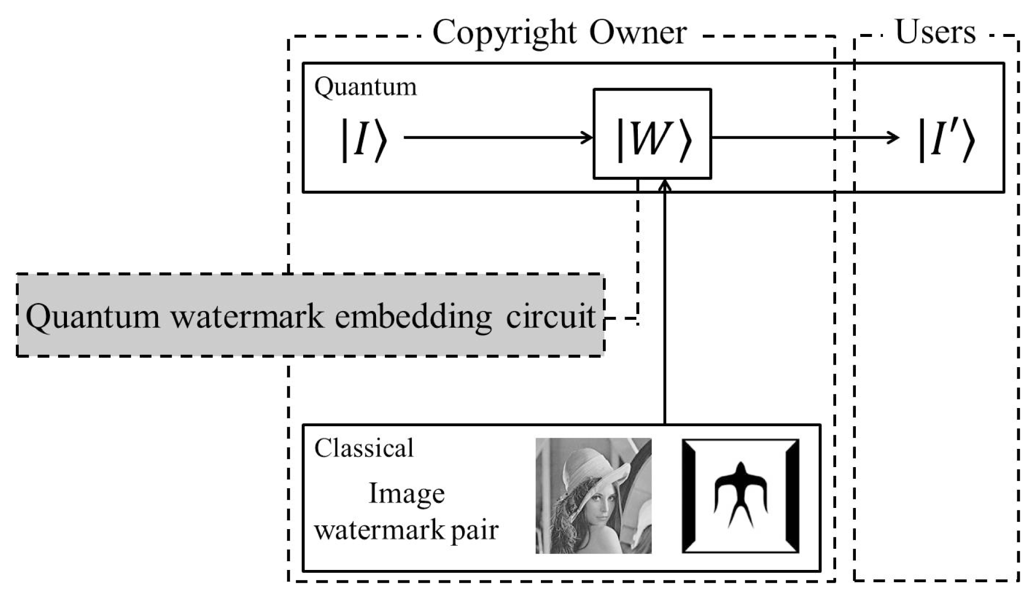
  • In the watermark blending step, it is on the basis of the classical version of the image-watermark pair completely.
  • In the watermark circuit transformation step, the content retrieved from the blending step are transformed into applicable quantum circuit elements.
The combination of these two steps achieves the watermark embedding circuit, and the primary purpose of this algorithm is to determine the sub-areas within the cover image that can withstand tolerable distortion and, also, the type of quantum operations to apply in each sub-area.
The size and nature of information in each sub-area are mainly taken into the consideration in the former part of the algorithm. Accordingly, the algorithm tries to reach an agreement between these two parameters. The latter part of the algorithm, in order to determine the appropriate rGTQI operations to apply on each sub-area, concentrates on using the information about the predetermined sub-areas. To accomplish this, the restricted geometric transformations reviewed in Section 2.3 become very important. By utilizing the content of the classical versions of each image-watermark pair, the watermark embedding circuit generation algorithm as discussed in [33,51] gives a blended watermark representation, which determines the watermark circuit for that pair in turn.

6.2. Two-Tier Grayscale Version of the WaQI Protocol

As a paragon in the area of quantum image watermarking, the WaQI protocol was found to have a few areas that need improvement. Consequently, utilizing the same FRQI representation, a few schemes have been proposed to revise, improve and extend the WaQI strategy. In this subsection, we shall review the two-tier grayscale version of the WaQI scheme, or simply the GWaQI scheme, that was first proposed in [34] and subsequently reviewed in [51]. The purpose of the GWaQI scheme is to implement a bi-level scheme that includes embedding a conspicuous watermark logo in a predetermined sub-area of the cover image; meanwhile, the same watermark signal is embedded to cover the rest of the image in an obscure manner. For the visible watermark embedding, the digital watermarking method [54] is modified with the inherent “quantumness” of the information carrier to realize its implementation on the quantum computation framework. The invisible watermark embedding is considered to further safeguard the copyright of the original image and to discourage its unauthorized reproduction. The general circuit of this two-tier watermarking strategy for the FRQI quantum images is shown in Figure 29. The circuit consists of two sub-circuits, which are for embedding the visible and invisible watermark signal, respectively. The visible and invisible watermark embedding transformations Tα and Tβ are confined to predetermined areas of the cover image using the control-conditions specified by IRl and IS, respectively.

6.3. A Watermark Strategy for Quantum Images Based on Quantum Fourier Transform

Another quantum watermarking strategy that extends on the WaQI protocol is based on the use of the quantum Fourier transform (QFT) [49], so that the real owner of the image could be found effectively. In addition, the QFT in this strategy can guarantee that the watermark image is still discernible, even after the carrier image is attacked by illegal users. The watermark image is preprocessed to be meaningless, and a slight change to the Fourier coefficients of the carrier image is made in line with the preprocessed watermark image in the watermark embedding procedure.
The image-scrambling method in this subsection is tailored to render the image content unintelligible, and the keys for scrambling are only known to the operator. A novel scrambling method was described in [49], given a image sized m×n, two random permutations (M and N with size m and n, respectively) generated by the operator could change the quantum image to be meaningless. Concretely, suppose M(i), N(j) are the ith and jth numbers in M, N; the pixel at position (i,j) of the new image would be replaced by the pixel (M(i), N(j)) of the original image. If we execute such an algorithm on all of the pixels of the original images, it will be scrambled and become meaningless.
The property of QFT needs the revised value of the QFT coefficients to be symmetrical, so that the pixels’ value of the embedded carrier image could remain real. Therefore, both the carrier image and watermark image for the watermarking should be symmetrical. The watermark embedding procedure is listed as below:
  • Watermark image preprocessing.
    Generate two sequences of keys and then scramble the watermark image according to the image scrambling method introduced earlier.
  • Execute QFT on the carrier image and obtain its Fourier coefficients.
  • Embed the watermark image into the carrier image.
    If we only take the color information of a FRQI quantum image into consideration, we can assume the final revised watermark image is i = 0 M N - 1 ω i i , the carrier image is i = 0 M N - 1 x i i and the QFT of the carrier image is i = 0 M N - 1 y i i . Therefore, the Fourier transform of the embedded carrier image is in the following form: i = 0 M N - 1 y i i = i = 0 M N - 1 ( y i + α * ω i ) i , where α decides the embedded proportion (0 < α < 1).
  • Execute the inverse QFT to obtain the embedded carrier image.
The extraction procedure is to extract the watermark image from the embedded carrier image, which is the reverse operation of embedding processing. Interested readers can find the elaboration in [49].

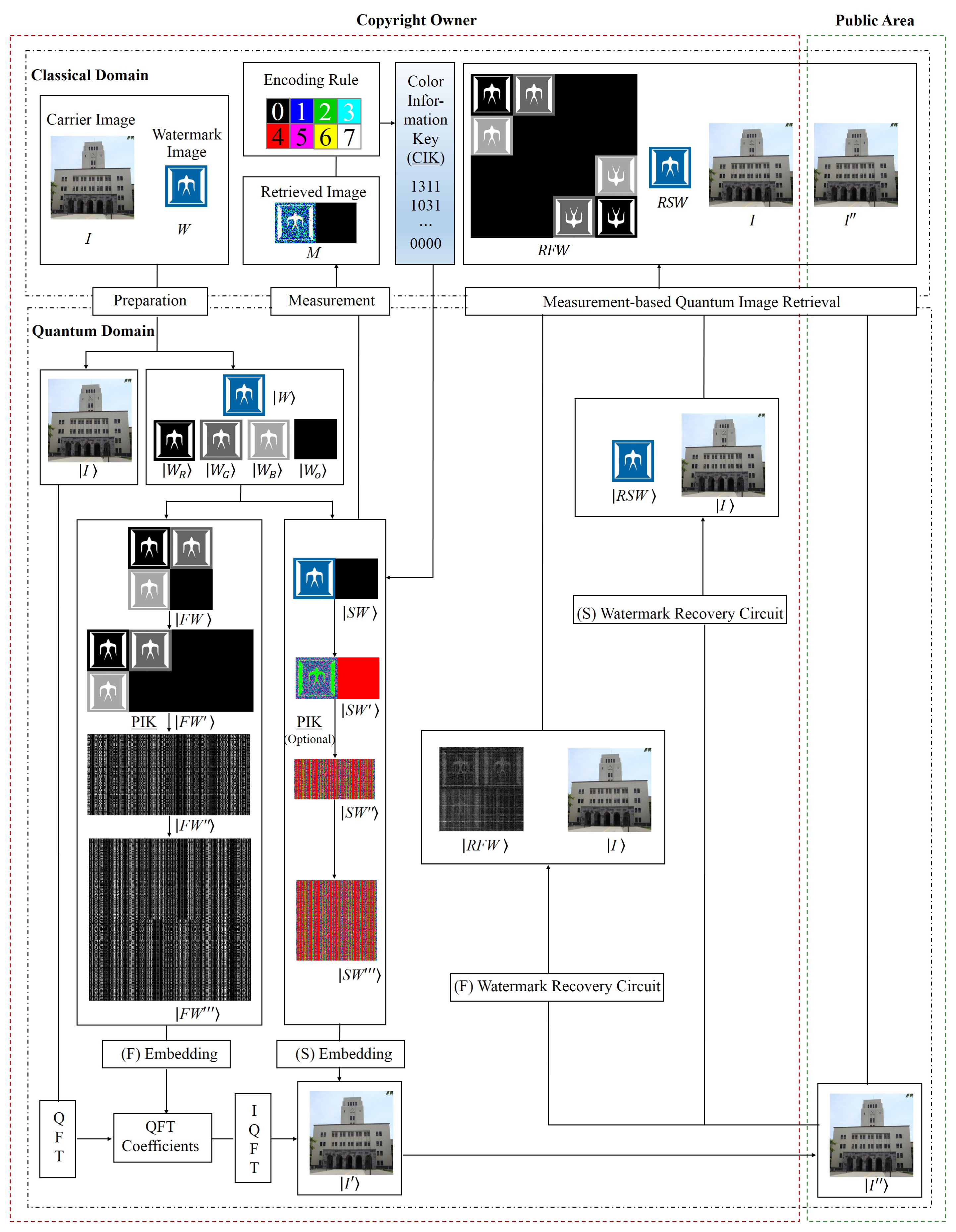
6.4. A Duple Watermarking Strategy for Multi-Channel Quantum Images

While the grayscale WaQI (GWaQI) and the QFT WaQI schemes are based on the FRQI representation to encode the carrier image and watermark, the duple watermark strategy reviewed in this subsection is based on the multi-channel representation for quantum images, MCQI, for both the carrier and watermark images.
The watermarking and authentication of quantum images (WaQI) in Section 6.1 is indisputably credited with pioneering research in the sub-field of quantum image watermarking. It is also regarded as a secure, keyless and blind protocol for quantum image watermarking and authentication. A major shortcoming of the protocol, however, is that it could be only used to authenticate whether the carrier image belongs to a certain one or not, because we have to know the content of watermark image first, so as to design the quantum circuit for the authentication. While the quantum image watermarking strategy in Section 6.3 embeds the logo information into quantum Fourier transform (QFT) coefficients, so that illegal users cannot understand what the watermarked information means, even though they extract it from the watermarked image, however, it is still dangerous if the “fixed” key is stolen by them. In addition, both of these two watermarking strategies are used for dealing with grayscale quantum images only.
A new multi-channel watermarking strategy for quantum images, or simply the MC-WaQI [50] strategy, is introduced in this subsection. It is designed as a multi-layer double-key and double-domain format in a manner that enhances the security of the watermarked images. As the name of the strategy suggests, the MC-WaQI strategy is based on the MCQI representation (discussed in Section 3.1) for both the color carrier and watermark images. Similar to its paragon, the WaQI protocol, the general framework of watermarking for MCQI quantum images is shown in Figure 30, which is delineated into two broad divisions. The first domain is comprised of all of the data available to the copyright owner, i.e., the publisher of the watermarked image, while the second domain consists of the information published for the public users. Therefore, the tasks, such as preprocessing, embedding and extraction, are handled by the copyright owner, who has exclusive permission to access these data.
In detail, this strategy could be realized by the following three steps:
(1)
Preprocessing procedure:
  • Prepare for MCQI quantum images |I〉 and |W〉 from the classical version of them I and W.
  • Create two watermark information |FW〉 and |SW〉 from the original watermark image |W〉 for the embedding into both frequency and spatial domains of the carrier image.
  • Apply measurement operation on image |SW〉 to obtain retrieved image M.
  • Generate the color information key (CIK) from image M by means of the encoding rule.
  • Execute operations on |SW〉 using CIK to get image |SW′〉.
  • Compose image |FW′〉 from image |FW〉.
  • Scramble image |FW′〉 to obtain image |FW″〉 by applying the position information key (PIK) operation, and it is an optional operation to scramble image |SW′〉 to |SW″〉.
  • Resize image |FW″〉 and |SW″〉 to get image |FW‴〉 and |SW‴〉.
(2)
Embedding procedure:
  • Embed image |FW‴〉 into the QFT coefficients of the carrier image to transform image |I〉 to image |I′〉.
  • Embed image |SW‴〉 into the spatial domain of image |I′〉 to generate image |I″〉.
(3)
Extraction procedure:
  • Extract watermark image |RFW〉 from the frequency domain using PIK.
  • Extract watermark image |RSW〉 from the spatial domain using CIK (probably with PIK, depending on the preprocessing procedure).
In the scheme, two sets of watermark information are created from the original watermark image and embedded into both the frequency and spatial domains of the carrier image, so that the robustness of the published (watermarked) image to attack by vandals is enhanced. Meanwhile, two sets of keys are generated in the procedure with one of them (color information key, or CIK) randomly updated by each quantum measurement operation on the carrier image. This further protects the color information of the watermark image. The second key, the position information key (or simply, PIK), as introduced in Section 6.3, is pre-assigned by the copyright owner, and using it, the position information of the watermark image is scrambled beyond comprehension, thus rendering the image meaningless. After the preprocessing, the two sets of watermark information are embedded into the frequency and spatial domains of carrier image, respectively. Finally, the watermark quantum image could be extracted from the two domains using a watermark recovery circuit that is only available to the copyright owner. Furthermore, the quantum images can be retrieved as classical versions by simple quantum measurements. Our duple watermarking strategy in the double domain with double keys provides more secure protection for the copyright protection of quantum images. We refer the interested readers to find a detailed discussion in [50]. From there, we can see that the proposed method produces watermarked images of acceptable quality.
The qualities of the embedded images in the forgoing four watermarking methods are evaluated by the average peak signal-to-noise ratio (PSNR). It is particularly worth mentioning that the RGB-PSNR [55,56] for the evaluation of color embedded image as presented in Equations (77)(79),
P S N R R G B = ( P S N R R + P S N R G + P S N R B ) / 3 ,
where:
P S N R X = 20 l o g 10 ( 255 M S E ) , X { R , G , B } ,
M S E = 1 m n i = 0 m - 1 j = 0 n - 1 [ R ( i , j ) - I ( i , j ) ] 2 .
Here, MSE is the mean squared error between the carrier image I(i, j) and the embedded image R(i, j), where m and n are the number of pixels in the image.

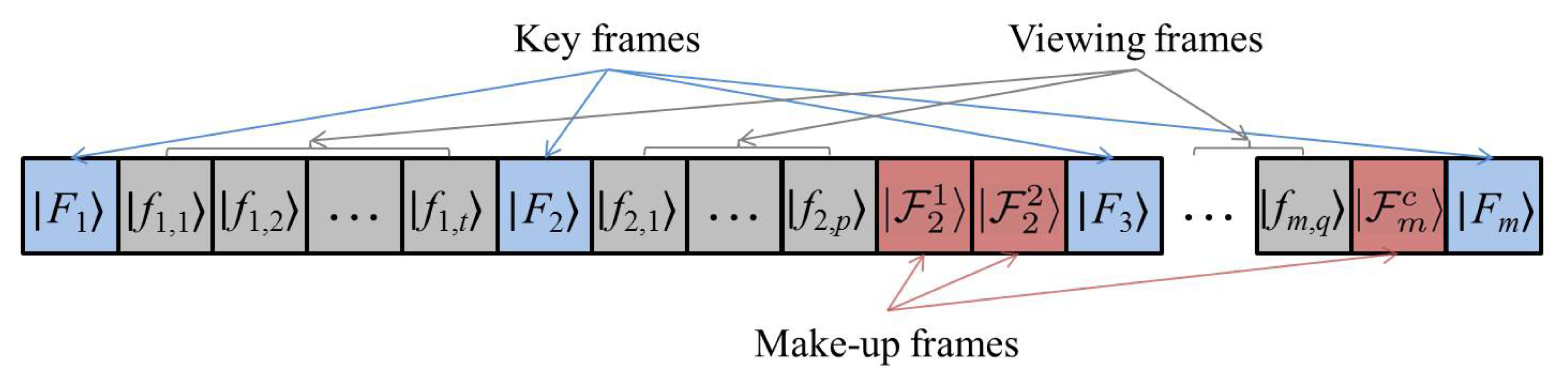
7. A Framework for Representing and Producing Movies on Quantum Computers

As a testimony to the utility and adroitness of FRQI quantum image processing, a framework to represent and produce movies (simply called quantum movies) on quantum computers was discussed in [12,39] and later reviewed in [51]. Akin to most of the applications reviewed in this work, in the quantum movie framework, the broadest content in a movie, the frame, is an FRQI quantum image. To extend such a framework to MCQI encoded frames requires an in-depth understanding of the quantum movie framework. This section reviews the introduction and motivation reported in [12], which was focused on extending the classical movie applications and terminologies to a new framework that could facilitate movie representation and production on quantum computers.

7.1. Framework for Quantum Movie Representation and Manipulation

It was reported in [12] that, classically, there are four levels needed to convey a storyline to the audience in a movie. First, a movie includes a series of similar images called frames, which could be assembled into a shots. Then consecutive shots are aggregated into scenes, according to their pertinence. Finally, a sequence of all scenes together composes a movie. As with many other applications, however, extending the classical movie architecture to the quantum computing domain will be a daunting task. It was noted in [12] that the classical terminologies and role need to be extended. For example, in analogy with the classical compact disc-CD (or cassette) and CD (VCD, DVD or VCR) player, several conceptual device adopted in quantum movie, i.e., quantum CD, quantum player and movie reader, are used to achieve the preparation, manipulation and measurement of quantum movie on quantum computers. The quantum CD encodes, prepares and initializes the broad content (key frame) conveying the movie script. Then, the quantum player manipulates the contents of the key frames by using the simple motion operations in order to interpolate the missing viewing frames required to effectively smooth the shots and scenes of the movie. Finally, the movie reader retrieves the classical movie sequence comprising both the key and viewing frames for each shot through combining the projective measurement technique and the ancilla-driven quantum computation. At appropriate frame transition rates, this sequence provides the impression of continuity, so as to depict a set of movements and actions in the movie.
Combining the quantum CD, quantum player and movie reader, a framework as shown in Figure 31 is presented in order to represent and produce movies on quantum computers. The movie enhancement of the movie reader is considered for the purpose of enhancing the content of each frame before final display to the audience. This enhanced content of the movie is given by the sequence:
M = 0 ( 0 , 0 , 0 , 1 , , 0 , p ) 1 0 , , 2 m - 1 × ( m - 1 , 0 , m - 1 , 1 , , m - 1 , q ) , 2 m .

7.2. Quantum Video Encryption and Decryption Protocol

Multimedia data security has gradually aroused people’s attention with the rapid development of computer technology and Internet technology. Some special videos, e.g., the videos used by the military and business, need to be protected before communication on the Internet. Adopting the basic foundations established by the quantum movie framework, we present in this subsection a method for quantum video encryption and decryption [52]. First of all, the quantum movie presented in the last subsection is improved to color quantum video by extending the FRQI representation for the frames to the MCQI representation that captures RGB color information for images in Section 3.1.
Similarly, the definition of a strip encoding FRQI grayscale image in quantum movie is extended to the analogous one that comprising 2m MCQI quantum images (M-strip), which is formulated as:
S ( m , n ) m c = 1 2 m / 2 s = 0 2 2 m - 1 F s ( n ) s ,
where:
F s ( n ) = 1 2 n i = 0 2 2 n - 1 C R G B α s , i i ,
C R G B α s , i = cos  θ R s , i 000 + cos  θ G s , i 001 + cos  θ B s , i 010 + cos  θ α 011 + sin  θ R s , i 100 + sin  θ G s , i 101 + sin  θ B s , i 110 + sin  θ α 111 ,
θ s , i [ 0 , π 2 ] , i = 1 , 2 , , 2 2 n - 1 , s = 1 , 2 , , 2 m - 1 ,
where, similar to the notation in Definition 1, |s〉 is the position of each image in the strip, m is the number of qubits required to encode the strip and |Fs(n)〉 is an MCQI quantum image, as defined in Equation (24) at position |s〉.
The circuit structure for the M-strip is presented in Figure 32, and it is used in a horizontally-oriented manner in the ensuing discussions [12,36,37]. The basic definitions for a key frame, viewing frame and makeup frame in [12] are adopted to describe our proposed quantum video in this subsection. Key frame representation is used to capture the most important information of video for content browsing and retrieval. The frames between each two key frames (called the viewing frames) is used to smooth the change of the content over time, while the makeup frame is adopted when it is difficult to convey a video by transforming a preceding key frame in a scene. For a quantum video, each frame (whether key, makeup or viewing frame) is an MCQI state, as defined in Equation (24), while any combination of multiple frames (a strip) is best represented as an mMCQI state. The proposed schematics for these three kinds of frames is outlined in Figure 33.
For the encryption procedure of quantum video, firstly, prepare a copy of the key frames to do the quantum measurement, so that generating the color information keys, as introduced in Section 6.4. The color information in the frame will collapse when the quantum measurement is applied on the basis of the quantum state measurement property. Taking a purple quantum pixel as an example, which could be decomposed to R (128), G (64) and B (128), as shown in Figure 34, however, we can only obtain black and white with probabilities on each channel after the measurement on these three channels. It is concluded that there are only eight possible colors in the post-measurement image based on the RGB color model. Then, according to the encoding rule with different operations (channel of interest and channel swapping operations) in Section 6.4, each frame in the video will become discernible, so as to achieve the encryption. Finally, store all of the keys in a matrix to improve the security factor by utilizing matrix transformations. Since all of the transformations used in quantum computation are unitary transformations, the encryption procedure is completely reversible.
The quantum video encryption protocol utilizes quantum measurement properties and leads the encryption used color information key to be different every time, which enhances the security of a video. In addition, the operations on the strip wires allow one to encrypt all of the frames of the video at the same time, and also, it is possible to constrain the encryption operation to any region of interest in a particular frame of the video. More details about the encryption and decryption protocol could be found in [52].

8. Likely Technologies to Realize Quantum Image Processing Applications and Concluding Remarks

Prof. David Deutsch, a key figure in the quantum computation and quantum information processing area, is credited to have said “Quantum computers have the potential to solve problems that would take a classical computer longer than the age of the universe”. Combined with the celebrated Moore’s law asserting that the number of transistors on integrated circuits doubles almost every eighteen months, at a certain level, another kind of computing paradigm will be needed in order to guarantee the miniature level and power associated with our computing devices. One such technology widely touted as the core of next generation computing devices is quantum computing. This has invigorated many institutes and enterprises into research focused on the quantum algorithms and realization of quantum computing hardware.
Buoyed by this and the growing interest in quantum image processing (QIP) in general, as well as the enthusiasm generated by FRQI QIP in particular, Iliyasu et al. espoused the realization of FRQI QIP application-specific hardware to the advances made in photonic (or optical) quantum computing technologies to provide an insightful compendium of the level of maturity in the area and the likely impediments to the realization of QIP quantum computing hardware.
This section briefly reviews these technologies, and since, the main focus of this paper is on FRQI algorithmic applications, we refer interested readers to [57] for more details on the realization of FRQI QIP hardware.

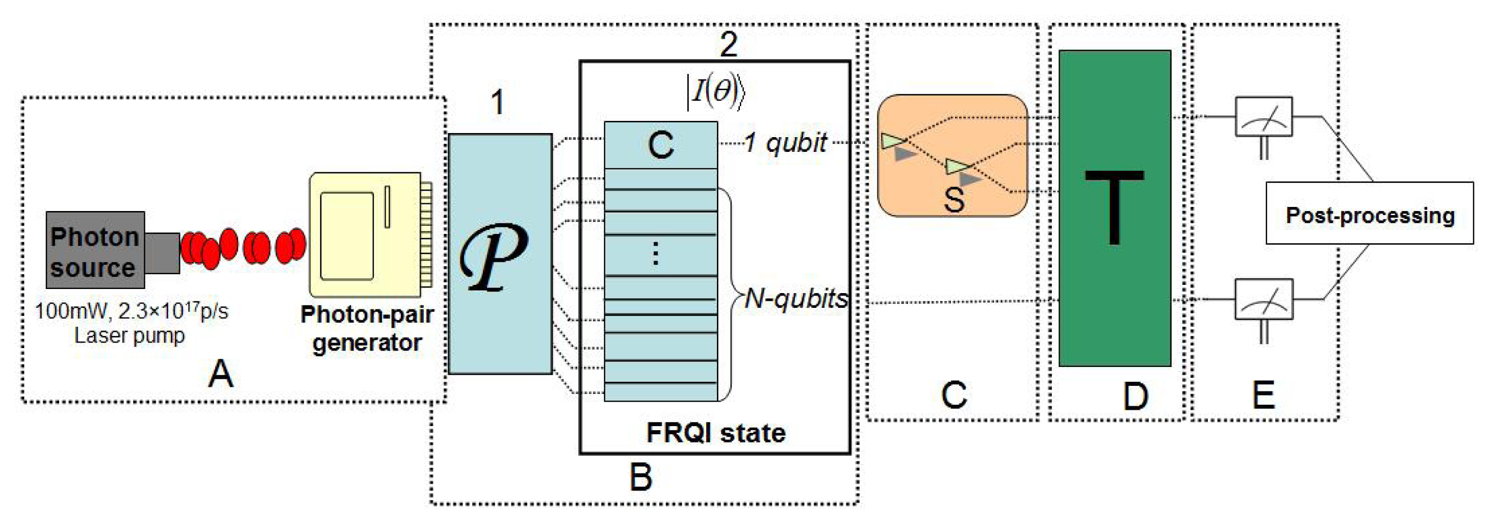
8.1. Photonic-Based Realization of Efficient FRQI Quantum Image Processing

The flow and discussion of the proposed model to realize photonic-based quantum image processing applications follows the footsteps of a similar discussion in [58]. Therefore, the proposed implementation of the FRQI representation and its transformation will be based on the architecture presented in Figure 35. As in [58], the discussions here are limited to the nature of photonic devices or components that are required to perform the operations in the various blocks of the scheme along the line of the three criteria that are adopted to realize the photonic FRQI quantum image processing application-specific device, i.e., the criteria for quantum image state preparation, manipulation and recovery. For each criterion, we will speculate on the modifications needed to accomplish specific image processing tasks that appear intractable using available technology. In doing so, we will relate each image processing task to the appropriate device or tool in the sub-blocks.

8.1.1. Photonic-FRQI Quantum Image Preparation

The first device needed in the photonic quantum image processing architecture is the photon source. An uninterruptible photon source (UPS) consists of a primary source pumped by a laser, akin to the power (voltage) source of a traditional classical gadget, to produce the photon pairs, which is labeled as Block A in Figure 35.
As reviewed in Section 2 and [57], the PPT theorem to prepare an FRQI quantum image can be divided into two parts. The first part by applying the transform comprising of 2n + 1 Hadamard operations transforms the vacuum state, |0〉⊗2n+1, to the ghost FRQI state, |H〉. Since both the vacuum state and the Hadamard operations (single qubit beam splitters) have been realized and implemented physically, it is trivial to assume that the ghost FRQI state, |H〉, for any n×n image can be realized. Figure 36 shows the execution of the transformation to transform the vacuum state into a ghost FRQI state. The second part of the PPT theorem, the transform, requires 22n controlled-rotation or the generalized C2n(Ry(2θi)) operation to accomplish this [26]. Multiple-qubit operations on quantum states are still challenging to realize using photonic or quantum technologies. Therefore, when restricted within the confines of today’s technologies and the requirements of the transform, as discussed in [21], only a 2×2-pixel image, i.e., the case where n = 1, can be realized. The sub-circuit to execute the transform for such a small-sized image (as shown in Figure 10 in Section 3.2) requires two controlled-rotation and two controlled-NOT gates. As specified by the PPT theorem, preparing a 2 × 2 FRQI quantum image requires a total of 40 simple quantum operations [21,26]. This limitation regarding the size of images we can realize from available technology is attributed to the lack of quantum optical elements to execute multiple-control condition operations. The best we can realize for larger-sized images is the intermediary ghost FRQI quantum image state arising from the application of the transform on the initialized vacuum state as specified by the FRQI PPT theorem. Such a transformation to transform an n-qubit vacuum state to its intermediary or ghost FRQI state is depicted in Figure 36.
Consequently, meaningful FRQI quantum image states can only be realized if the optical components to execute the transform, comprising multiple controlled-operation gates, are made available. Fortunately, the continued interest of practitioners, as evinced by the vigorous on-going research in the field coupled with the sophistication in experiments, indicates that these challenges will soon be overcome [5961]. The FRQI state shown in Block B of the proposed implementation of FRQI photonic quantum image processing in Figure 35 assumes the execution of the transform, and therefore, an image comprising of is 2n + 1 realized.

8.1.2. FRQI Quantum Image Transformation on Photonic Quantum Computers

The generalized transformation, T, step in block D of the proposed implementation of FRQI quantum image processing using photonic quantum technologies involves transforming the single channel FRQI quantum image comprising the 2n + 1 qubits (or if implemented, the multiple channel FRQI quantum image state comprising 2n + 3-qubits image) realized from the discussions in the preceding subsection. This transformation comprises of the various circuitries to modify the input quantum image to a new form, which could be its watermarked version, as reviewed in Sections 6, or a viewing frame in a quantum movie, as in Section 7. Depending on the purpose of the transformation circuit and the size of the input image, the sub-circuits in T may require a lot of control-conditions to execute. The lack of photonic quantum technologies to perform these operations, however, limits the extent of image processing tasks we can accomplish at present.
The dexterous structure of the FRQI representation, which dedicates only one qubit to encode the color content of an FRQI quantum image, however, allows us to perform color-based transformations, CTQI, as highlighted in Section 2.4, on the content of the entire image. Most of the optical elements to perform the single qubit color transformations X, H, Z and C(2θ) have been realized already and detailed in numerous optical and photonic quantum computing literature, notably [15,59,62]. Confining these CTQI transformations to smaller sub-areas of an image for advanced image processing applications, however, is still an arduous task to accomplish. This is attributed to the fact that we need additional control-conditions to restrict the effect of the transformations to the predetermined sub-block(s) of the image. These multiple control-conditions have so far proven to be the main obstacle mitigating meaningful FRQI quantum image processing on photonic quantum computers. Within the restrictions of today’s technologies, we can also perform single qubit color transformations on any of the three channels, as realized up to Block C of the schematic for implementing photonic FRQI quantum image processing (Figure 35).

8.1.3. Recovering Photonic-FRQI Quantum Image States

The last step of the proposed implementation of photonic-FRQI quantum image processing entails, as with other quantum information processing procedures, recovering the final state of the image. The avalanche photon-detector (APD) remains the most widely used source of detecting photons. Therefore, this device is sufficient to recover the generalized photonic quantum states. However, for the FRQI quantum image processing, the target is to determine the new state (after numerous modifications) of the photons used to encode the content of the original image. Relying on the fact that FRQI quantum image states are size-preserved [12], our focus is therefore narrowed to tracking the changes that the color angle encoding each pixel went through as it passed through the various layers and sub-circuits of the transformation circuit. In the end, what we obtain will be a stream of color angles θ i [ 0 , π 2 ], i = 0, 1, …, 22n − 1 spanning the entire pixels of the image. This actually conforms to what is obtained in classical image processing, wherein an image is described by a bunch of numbers: 0–1 for binary images; 0–255 for grayscale images; and so on.
Tracking the changes that the color information undergoes, however, is itself a very daunting task, as demonstrated in the movie reader in Section 7. Therein, 22n ancillary qubits were used to encode the color of every pixel in the input images. The interaction operation of the ancilla-driven quantum computing [44] model was then used to transfer the final state of the pixel (using the qubit) to its corresponding ancilla qubit. Destructive measurements to “see” these new states were then performed on these ancilla qubits. This way, the transformed state of the image was recovered without disturbing the content of the images encoded and transformed in the movie strip, as presented in Section 7. This technique facilitated the recovery of the content of a movie sequence comprising of the key, viewing and make-up frames. Even so, the content recovered was binary, 0–1, states [34]. Implementing this primal FRQI quantum image state recovery with today’s photonic quantum technologies is also a victim of the need for multiple control-condition operations. Actually, even with the realization of optical elements to execute multiple control-condition operations, as mentioned in the preceding discussions, the cost of implementing a read-out similar to the one enumerated in [12] appears very high. Therefore, recovering the final state of the FRQI quantum image on photonic quantum computers will pose the most difficult challenge when compared alongside the other two criteria we have adopted for realizing our photonic-FRQI quantum image processing application-specific device, i.e., the quantum image state preparation and manipulation criteria.
As in classical image processing, the string of values encoding the information about the pixels that make up an image must be further processed for any meaning to be made of its content. We, therefore, envisage the need for a similar post-processing step, perhaps using classical resources, to transform the string of color-related (angle) values into a form comprehendible to the human eye.

8.2. Concluding Remarks

The main focus of the work presented in this review is aimed at providing an enriching, yet subtle, compendium of the advances made in the new and exciting sub-field of quantum image processing (FRQI quantum image processing in particular) over the past five years. In so many ways, the review builds on the work in [51]. In a similar manner, this paper addresses the important question of what can be done when we eventually realize a quantum computer.
The paper describes how traditional image processing tasks and applications can be executed on the quantum computing domain. For this, we started by reviewing, in Section 2, the now widely accepted flexible representation of quantum images (FRQI), which captures and stores the essential information of an image as a normalized quantum state and its related transformations on the position and color information. The transformations provide the foundation for the later introduced quantum image processing applications. To process color images on quantum computers, an extension of FRQI representation, multi-channel representation for quantum images (MCQI), encoding information from R, G and B channels is reviewed in Section 3. Three types of operators are introduced for processing the MCQI quantum images, i.e., (1) channel of interest operator (CoI), which shifts the grayscale value of the color channel of interest (R, G, B or α channel); (2) the channel swapping operator (CS), which is used to swap the grayscale values between two channels (R and G, R and B or G and B channels); and (3) α blending (αB), which is used to blend an image with a background image to create the appearance of partial or full transparency.
Exploiting the flexible features of the FRQI representation and related various transformations, a method to compare multiple pairs of quantum images in parallel, where the similarities of the images are estimated by means of the probability distributions of the readouts from quantum measurements, is introduced in Section 4, which offers a significant speed-up in comparison to performing the same task on traditional computing devices by using a single Hadamard gate with control-conditions to transform all of the information encoding the quantum images in a strip. The comparison between the sub-blocks from two arbitrary images can be realized by utilizing appropriate geometric transformation operations on the strip wires, as well as the required control conditions to the position wires. On the basis of such a quantum image comparison strategy, a quantum image searching method is given in Section 5, which is achieved by using low computational resources, which are only a single Hadamard gate combined with m + 1 quantum measurement operations. A simulation experiment is performed to search for a target image from an original database comprising of sixty-four binary images. According to the readouts from the measurements, the similarity of each pair between the test image and the images in the database is calculated. It is concluded that the more images in the database, the better the ability of the proposed method. This is because m qubits on the strip wires can represent 2m quantum images in the Z-strip, and only one qubit on the Z-axis can represent the images on both the left and right side of Z-strip.
In order to protect the quantum image information, several watermarking strategies on quantum images are discussed in Section 6. We started by reviewing the pioneering quantum image watermarking protocol—the watermarking and authentication of FRQI quantum images based on restricted geometric transformations (WaQI); then based on this, the two-tier scheme for FRQI quantum images watermarking and recovery and quantum Fourier transform (QFT)-based watermark strategy for the grayscale quantum images were reviewed. The latter strategy was used as a reference to realize a duple watermarking strategy for MCQI quantum images, which was also reviewed in the same section. The multi-channel watermarking strategy for quantum images (MC-WaQI) utilizes the double-key and double-domain idea to make the watermarking more secure and also provides an effective way to process the color quantum images. The simulation results of the embedding and extraction experiments show that the average RGB-PSNR between each carrier image and its embedded image is bigger than the previous research.
Inspired by how image processing research and applications led to video processing application, an interesting attempt was made to extend the quantum image processing algorithmic frameworks to the video (or movie) processing applications in [12]. This presents a new framework that facilitates movie representation and production on quantum computers from the classical movie applications and terminologies. Based on this framework, a classical-like movie can be produced by means of the quantum CD, quantum player and movie reader. This framework was briefly reviewed in Section 7, and later used as the pith on which our proposed quantum video encryption and decryption is realized. Such a encryption protocol ensures the secure transmission and sharing of video in quantum communication.
Finally, in Section 8, we presented a brief review of efforts made to assess availability of technologies to realize some of the applications highlighted in the preceding sections. Photonic quantum technologies were considered among the most suitable technologies for the realization of FRQI QIP application-specific hardware.
Overall, the algorithmic frameworks reviewed in this paper together with the extensions that were suggested in the various sections provide the road-map towards the realization of secure and efficient image and video processing on quantum computers. New applications and extensions can be discovered by new contributions in other allied research areas. Quantum computing research still has a long way to go; therefore, additional research is needed in the area of quantum image processing in order to ensure a plethora of applications when we eventually realize quantum computing hardware, which will be at the core of our next generation computing devices.

Acknowledgments

Fei Yan and Abdullah M. Iliyasu appreciate the professional comments and criticisms from Kaoru Hirota and Fangyan Dong. The productive and memorable collaboration with Phuc Q. Le and Bo Sun is also immensely appreciated.

Author Contributions

Fei Yan and Abdullah M. Iliyasu contributed to the proposals and the discussion of the results. Zhengang Jiang was involved in the discussion of the results and final proofreading of the manuscript. All authors have read and approved the final manuscript.

Conflicts of Interest

The authors declare no conflict of interest.

References

  1. Yan, F. Quantum Computation Based Image Data Searching, Image Watermarking, and Representation of Emotion Space. Ph.D. Thesis, Tokyo Institute of Technology, Tokyo, Japan, 2014. [Google Scholar]
  2. Iliyasu, A. Algorithmic Frameworks to Support the Realisation of Secure and Efficient Image-Video Processing Applications on Quantum Computers. Ph.D. Thesis, Tokyo Institute of Technology, Tokyo, Japan, 2012. [Google Scholar]
  3. Feynman, R. Simulating physics with computers. Int. J. Theor. Phys 1982, 21, 467–488. [Google Scholar]
  4. Deutsch, D. Quantum theory, the church-turing principle and the universal quantum computer. Proc. R. Soc. Lond. A 1985, 400, 97–117. [Google Scholar]
  5. Shor, P. Algorithms for Quantum Computation: Discrete Logarithms and Factoring. Proceedings of the 35th Annual Symposium on Foundations of Computer Science, Santa Fe, NM, USA, 20–22 November 1994; IEEE Computer Society: Washington, DC, USA; pp. 124–134.
  6. Politi, A.; Matthews, J.; O’Brien, J. Shor’s quantum factoring algorithm on a photonic chip. Science 2009, 325, 1221–1222. [Google Scholar]
  7. Grover, L. A fast quantum mechanical algorithm for database search. Proceedings of the 28th Annual ACM Symposium on Theory of Computing, Philadelphia, PA, USA, 22–24 May 1996; pp. 212–219.
  8. Dodd, J.; Ralph, T.; Milbum, G. Experimental requirements for grover’s algorithm in optical computing. Phys. Rev. A 2003, 68, 1–8. [Google Scholar]
  9. Chow, J.M.; Corcoles, A.D.; Gambetta, J.M.; Rigetti, C.; Johnson, B.; Smolin, J.; Merkel, S.; Poletto, S.; Rozen, J.; Rothwell, M.B.; et al. High-fidelity gates towards a scalable super-conducting quantum processor. APS March Meeting 2012, Boston, MA, USA, 27 February–2 March 2012; pp. 1–6.
  10. Beth, T.; Rotteler, M. Quantum algorithms: Applicable algebra and quantum physics. Springer Tracts Mod. Phys 2001, 173, 96–150. [Google Scholar]
  11. Schenkel, T.; Lo, C.; Weis, C.; Schuh, A.; Persaud, A.; Bokor, J. Critical issues in the formation of quantum computer test structures by ion implantation. Nucl. Instrum. Methods Phys. Res. Sect. B 2009, 267, 2563–2566. [Google Scholar]
  12. Iliyasu, A.; Le, P.; Dong, F.; Hirota, K. A framework for representing and producing movies on quantum computers. Int. J. Quantum Inf 2011, 9, 1459–1497. [Google Scholar]
  13. Biham, E.; Brassard, G.; Kenigsberg, D.; Mor, T. Quantum computing without entanglement. Theor. Comput. Sci 2004, 320, 15–33. [Google Scholar]
  14. Barenco, A.; Bennett, C.; Cleve, R.; Divincenzo, D.; Margolus, N.; Shor, P.; Sleator, T.; Smolin, J.; Weinfurter, H. Elementary gates for quantum computation. Phys. Rev. A 1995, 52, 3457–3467. [Google Scholar] [Green Version]
  15. Nielsen, M.; Chuang, I. Quantum Computation and Quantum Information; Cambridge University Press: Cambridge, UK, 2000. [Google Scholar]
  16. Cory, D.; Laflamme, R.; Knill, E.; Viola, L.; Havel, T.; Boulant, N.; Boutis, G.; Fortunato, E.; Lloyd, S.; Martinez, R.; et al. NMR based quantum information processing: Achievements and Prospects. Fortschr. Phys 2000, 48, 875–907. [Google Scholar]
  17. Yan, F.; Iliyasu, A.; Liu, Z.; Abuhasel, K.; Jiang, Z.; Dong, F.; Hirota, K. Representation of quantum emotion space using Bloch sphere. Proceedings of the Joint International Conference of ITCA 2014 and ISCIIA 2014, Hunan, China, 16–21 September 2014; pp. 1–6.
  18. Yang, Y.; Xia, J.; Jia, X.; Zhang, H. Novel image encryption/decryption based on quantum Fourier transform and double phase encoding. Quantum Inf. Process 2013, 12, 3477–3493. [Google Scholar]
  19. Zhou, R.; Wu, Q.; Zhang, M.; Shen, C. Quantum image encryption and decryption algorithms based on quantum image geometric transformations. Int. J. Theor. Phys 2013, 52, 1802–1817. [Google Scholar]
  20. Venegas-Andraca, S.; Bose, S. Storing, processing and retrieving an image using quantum mechanics. Proceedings of the 2003 SPIE Conference of Quantum Information and Computation, Orlando, FL, USA, 21–22 April 2003; 5105, pp. 134–147.
  21. Le, P.; Dong, F.; Hirota, K. A flexible representation of quantum images for polynomial preparation, image compression, and processing operations. Quantum Inf. Process 2011, 10, 63–84. [Google Scholar]
  22. Latorre, J.I. Image compression and entanglement. Quantum Phys 2005. arXiv:quant-ph/0510031. [Google Scholar]
  23. Venegas-Andraca, S.; Ball, J. Processing images in entangled quantum systems. Quantum Inf. Process 2010, 9, 1–11. [Google Scholar]
  24. Mutze, U. Quantum Image Dynamics—an Entertainment Application of Separated Quantum Dynamics. Available online: http://genie1.ma.utexas.edu/mp_arc/c/08/08-199.pdf accessed on 2008.
  25. Le, P.; Dong, F.; Hirota, K. Flexible Representation of Quantum Images and Its Computational Complexity Analysis. Proceedings of the 10th Symposium on Advanced Intelligent Systems (ISIS 2009); pp. 146–149.
  26. Le, P.; Iliyasu, A.; Dong, F.; Hirota, K. A flexible representation and invertible transformations for images on quantum computers. New Adv. Intell. Signal Process 2011, 372, 179–202. [Google Scholar]
  27. Sun, B.; Le, P.; Iliyasu, A.; Yan, F.; Garcia, J.; Dong, F.; Hirota, K. A Multi-Channel Representation for Images on Quantum Computers Using the RGBα Color Space. Proceedings of the IEEE 7th International Symposium on Intelligent Signal Processing (WISP), Floriana, Malta, 19–21 September 2011; pp. 1–6.
  28. Sun, B.; Iliyasu, A.; Yan, F.; Dong, F.; Hirota, K. An RGB multi-channel representation for images on quantum computers. J. Adv. Comput. Intell. Intell. Inf 2013, 17, 404–417. [Google Scholar]
  29. Le, P.; Iliyasu, A.; Dong, F.; Hirota, K. Fast geometric transformations on quantum images. IAENG Int. J. Appl. Math 2010, 40, 113–123. [Google Scholar]
  30. Le, P.; Iliyasu, A.; Dong, F.; Hirota, K. Efficient colour transformations on quantum image. J. Adv. Comput. Intell. Intell. Inf 2011, 15, 698–706. [Google Scholar]
  31. Sun, B.; Iliyasu, A.; Yan, F.; Garcia, J.; Dong, F.; Al-Asmari, A.; Hirota, K. Quantum computation based color information transformation on multi-channel image. Proceedings of the Ninth China-Japan International Workshop on Information Technology and Control Applications, Beijing, China, 28 June–1 July 2013; pp. 19–26.
  32. Sun, B.; Iliyasu, A.; Yan, F.; Garcia, J.; Dong, F.; Al-Asmari, A.; Hirota, K. Multi-channel information operations on quantum images. J. Adv. Comput. Intell. Intell. Inf 2014, 18, 140–149. [Google Scholar]
  33. Iliyasu, A.; Le, P.; Dong, F.; Hirota, K. Watermarking and authentication of quantum images based on restricted geometric transformations. Inf. Sci 2012, 186, 126–149. [Google Scholar]
  34. Iliyasu, A.; Le, P.; Yan, F.; Sun, B.; Garcia, J.; Dong, F.; Hirota, K. A two-tier scheme for greyscale quantum image watermarking and recovery. Int. J. Innov. Comput. Appl 2013, 5, 85–101. [Google Scholar]
  35. Iliyasu, A.; Le, P.F.D.; Hirota, K. Restricted geometric transformations and their applications for quantum image watermarking and authentication. Proceeding of the 10th Asian Conference on Quantum Information Sciences (AQIS 2010), Tokyo, Japan, 27–31 August 2010; pp. 96–97.
  36. Yan, F.; Le, P.; Iliyasu, A.; Sun, B.; Garcia, J.; Dong, F.; Hirota, K. Assessing the Similarity of Quantum Images Based on Probability Measurements. Proceedings of the IEEE Congress on Evolutionary Computation (CEC), Brisbane, Australia, 10–15 June 2012; pp. 1–6.
  37. Yan, F.; Iliyasu, A.; Le, P.; Sun, B.; Dong, F.; Hirota, K. A parallel comparison of multiple pairs of images on quantum computers. Int. J. Innov. Comput. Appl 2013, 5, 199–212. [Google Scholar]
  38. Yan, F.; Iliyasu, A.; Fatichah, C.; Tangel, M.; Betancourt, J.; Dong, F.; Hirota, K. Quantum image searching based on probability distributions. J. Quantum Inf. Sci 2012, 2, 55–60. [Google Scholar]
  39. Iliyasu, A.; Le, P.; Dong, F.; Hirota, K. A framework for quantum movie representation and production. Proceedings of the 2nd International Conference on Quantum Information and Technology (ICQIT 2010), Tokyo, Japan, 25–26 September 2010.
  40. Le, P.; Iliyasu, A.; Dong, F.; Hirota, K. Strategies for designing geometric transformations on quantum images. Theor. Comput. Sci 2011, 412, 1406–1418. [Google Scholar]
  41. Le, P.; Iliyasu, A.; Dong, F.; Hirota, K. Single qubit color transformations on quantum images. Proceedings of the 2010 International Symposium on Intellignet Systems (iFAN 2010), Tokyo, Japan, 25–26 September 2010.
  42. Iliyasu, A.; Venegas-Andraca, S.; Yan, F.; Sayed, A. Hybrid quantum-classical protocol for storage and retrieval of discrete-valued information. Entropy 2014, 16, 3537–3551. [Google Scholar]
  43. Lomont, C. Quantum convolution and quantum correlation algorithms are physically impossible. Quantum Phys 2003. arXiv:quant-ph/0309070. [Google Scholar]
  44. Anders, J.; Oi, D.; Kashefi, E.; Browne, D.; Anderson, E. Ancilla-driven universal quantum computation. Phys. Rev. A 2010, 82, 020301. [Google Scholar]
  45. Grover, L. Quantum mechanics helps in searching for a needle in a haystack. Phys. Rev. Lett 1997, 79, 325–328. [Google Scholar]
  46. Inoue, M. On the Need for Annotation-based Image Retrieval. Proceedings of the ACM-SIGIR Workshop on Information Retrieval in Context, Sheffield UK, 29 July 2004; pp. 44–46.
  47. Bennink, R.; Bentley, S.; Boyd, R. Quantum and classical coincidence imaging. Phys. Rev. Lett 2004, 92, 1–4. [Google Scholar]
  48. Chary, R.; Lakshmi, D.; Sunitha, K. Image Searching Based on Image Mean Distance Method. Proceedings of the 2012 International Conference on Radar, Communication and Computing (ICRCC), Tamilnadu, India, 21–22 December 2012; pp. 199–201.
  49. Zhang, W.; Gao, F.; Liu, B.; Wen, Q.; Chen, H. A watermark strategy for quantum images based on quantum Fourier transform. Quantum Inf. Process 2013, 12, 793–803. [Google Scholar]
  50. Yan, F.; Iliyasu, A.; Venegas-Andraca, S.; Dong, F.; Hirota, K. A duple watermarking strategy for multi-channel quantum images. Quantum Inf. Process 2014. submitted. [Google Scholar]
  51. Iliyasu, A. Towards realising secure and efficient image and video processing applications on quantum computers. Entropy 2013, 15, 2874–2974. [Google Scholar]
  52. Yan, F.; Iliyasu, A.; Venegas-Andraca, S.; Yang, H. Video encryption and decryption on quantum computers. Int. J. Theor. Phys 2014. submitted. [Google Scholar]
  53. Jiang, N.; Wang, L. A novel stratety for quantum image steganography based on Moiré Pattern. Int. J. Theor. Phys 2014. [Google Scholar] [CrossRef]
  54. Tsai, H.; Chang, L. Secure reversible visible image watermarking with authentication. Signal Process. Image Commun 2010, 25, 10–17. [Google Scholar]
  55. Di Martino, F.; Loia, V.; Sessa, S. Direct and inverse fuzzy transforms for coding/decoding color images in YUV space. J. Uncertain Syst 2009, 3, 11–30. [Google Scholar]
  56. Luthon, F.; Beaumesnil, B.; Dubois, N. LUX Color Transform for Mosaic Image Rendering. Proceedings of the IEEE International Conference on Automation Quality and Testing Robotics (AQTR), Cluj-Napoca, Romania, 28–30 May 2010; 3, pp. 1–6.
  57. Iliyasu, A.; Le, P.; Yan, F.; Sun, B.; Garcia, J.; Dong, F.; Hirota, K. Insights into the viability of using available photonic quantum technologies for efficient image and video processing applications. Int. J. Unconv. Comput 2013, 9, 125–151. [Google Scholar]
  58. Chuang, I.; Yamamoto, Y. Simple quantum computer. Phys. Rev. A 1995, 52, 3489–3496. [Google Scholar]
  59. Kok, P.; Munro, W.; Nemoto, K.; Ralph, T.; Dowling, J.; Milburn, G. Linear optical quantum computing with photonic qubits. Rev. Mod. Phys 2007, 79, 135–174. [Google Scholar] [Green Version]
  60. Gottesman, D.; Chuang, I. Demonstrating the viability of universal quantum computation using teleportation and sigle-qubit operations. Nature 1999, 402, 390–393. [Google Scholar]
  61. Bellini, M. Single-Photon-Level Light Manipulation and Amplification. Proceedings of the Conference on Quantum Information and Quantum Control, Toronto, ON, USA, 8–12 August 2011; pp. 8–12.
  62. O’Brien, J. Optical quantum computing. Science 2007, 318, 1567–1570. [Google Scholar]
Figure 1. Commonly used quantum gates (NOT, Z, Hadamard and CNOT).
Entropy 16 05290f1
Figure 2. A single qubit measurement gate.
Entropy 16 05290f2
Figure 3. A 2 × 2 FRQI quantum image, its circuit structure and quantum state.
Entropy 16 05290f3
Figure 4. Preparation of FRQI state through the unitary transform .
Entropy 16 05290f4
Figure 5. Generalized circuit design for geometric transformations on quantum images.
Entropy 16 05290f5
Figure 6. Single qubit gates applied on the color wire.
Entropy 16 05290f6
Figure 7. General circuit of MCQI quantum images.
Entropy 16 05290f7
Figure 8. A 2 × 2 MCQI quantum image, its circuit structure and MCQI state.
Entropy 16 05290f8
Figure 9. The general quantum circuit of UX operations, including: (a) UR; (b) UG; (c) UB; and (d) Uα.
Entropy 16 05290f9
Figure 10. C2Ry(2θ) can be constructed from basic gates, CRy(thetas;), CRy(−thetas;) and CNOT gates.
Entropy 16 05290f10
Figure 11. The general quantum circuit of UAB.
Entropy 16 05290f11
Figure 12. The general quantum circuit of UY operations: (a) URG; (b) URB; and (c) UGB.
Entropy 16 05290f12
Figure 13. Input images (A and B) and the circuit structure to realize α blending.
Entropy 16 05290f13
Figure 14. Circuit structure to encode the strip input.
Entropy 16 05290f14
Figure 15. Scheme to compare quantum images in parallel on quantum computers.
Entropy 16 05290f15
Figure 16. Generalized circuit structure for a parallel comparison of 2m −1 pairs of images.
Entropy 16 05290f16
Figure 17. Generalized circuit structure for parallel comparison of FRQI quantum images.
Entropy 16 05290f17
Figure 18. Parallel comparison of two Lena images and two “Man” images.
Entropy 16 05290f18
Figure 19. Circuit structure for realizing the comparison in Figure 18.
Entropy 16 05290f19
Figure 20. Histogram of the probabilities of the readouts in the measurements.
Entropy 16 05290f20
Figure 21. Circuit structure to encode the Z-strip input.
Entropy 16 05290f21
Figure 22. An example of Z-strip, its circuit structure and zFRQI state.
Entropy 16 05290f22
Figure 23. Generalized circuit structure for parallel comparison of quantum images in the Z-strip.
Entropy 16 05290f23
Figure 24. Block diagram of scheme to realize image searching on quantum mechanical systems.
Entropy 16 05290f24
Figure 25. Image searching from database |D〉.
Entropy 16 05290f25
Figure 26. Circuit structure for realizing the image searching in Figure 25.
Entropy 16 05290f26
Figure 27. Similarities among different pairs of images in the Z-strip.
Entropy 16 05290f27
Figure 28. Quantum image watermark-embedding procedure.
Entropy 16 05290f28
Figure 29. General circuit for the two-tier watermarking of grayscale FRQI quantum images.
Entropy 16 05290f29
Figure 30. General schematic for multi-channel watermarking strategy for quantum images (MC-WaQI).
Entropy 16 05290f30
Figure 31. Framework for quantum movie production.
Entropy 16 05290f31
Figure 32. Circuit structure to encode the M-strip input.
Entropy 16 05290f32
Figure 33. The key, makeup and viewing frames, |Fm〉, F m c and |fmq〉, respectively, from m-shots in a video.
Entropy 16 05290f33
Figure 34. Color collapse in quantum measurement.
Entropy 16 05290f34
Figure 35. Ansatz to realize the proposed device for photonic-based FRQI quantum image processing.
Entropy 16 05290f35
Figure 36. Photonic preparation of FRQI quantum image state.
Entropy 16 05290f36
Table 1. Comparison results for the sub-blocks from two images.
Image ComparisonProbabilitySimilarity
i 0 3 , i 3 2 Ps0 (|01〉) = 0.004sim(|i0〉, |i3〉) = 0.936
i 1 3 , i 2 3 Ps0 (|11〉) = 0.013sim(|i1〉, |i2〉) = 0.787

