Infrared Cloaking, Stealth, and the Second Law of Thermodynamics

Department of Physics, University of San Diego, 5998 Alcala Park, San Diego, CA 92110, USA
Entropy 2012, 14(10), 1915-1938; https://doi.org/10.3390/e14101915
Submission received: 6 July 2012
/
Revised: 8 September 2012
/
Accepted: 20 September 2012
/
Published: 15 October 2012
(This article belongs to the Special Issue Advances in Applied Thermodynamics)
Abstract
:Infrared signature management (IRSM) has been a primary aeronautical concern for over 50 years. Most strategies and technologies are limited by the second law of thermodynamics. In this article, IRSM is considered in light of theoretical developments over the last 15 years that have put the absolute status of the second law into doubt and that might open the door to a new class of broadband IR stealth and cloaking techniques. Following a brief overview of IRSM and its current thermodynamic limitations, theoretical and experimental challenges to the second law are reviewed. One proposal is treated in detail: a high power density, solid-state power source to convert thermal energy into electrical or chemical energy. Next, second-law based infrared signature management (SL-IRSM) strategies are considered for two representative military scenarios: an underground installation and a SL-based jet engine. It is found that SL-IRSM could be technologically disruptive across the full spectrum of IRSM modalities, including camouflage, surveillance, night vision, target acquisition, tracking, and homing.
1. Introduction
Signature management has existed as long as there have been predator and prey. In human affairs, it has been motivated by hunting and warfare for hundreds of thousands of years. Whereas signature management was once limited to optical and auditory signals, modern technology has extended its domain dramatically as greater spans of the electromagnetic and acoustic spectrums as well as other forms of radiation have become accessible.
Of the several electromagnetic regions pertinent to signature management [1,2,3], the infrared (IR) depends most critically on the second law of thermodynamics [4]. The IR spectral region extends from roughly 0.75–1,000 μm in wavelength. For most practical applications—and for the purposes of this study—relevant wavelengths are roughly 0.75–20 μm, with atmospheric windows of good infrared transparency at roughly 2–5 μm and 8–14 μm. Commercial IR detectors can achieve roughly 0.1 °C sensitivity and microsecond time resolution.
Thermal emissions have numerous technological, industrial, and scientific applications, but military applications have been perhaps the most studied, e.g., air-to-air and surface-to-air missiles “seeking” the hot exhaust from aircraft engines; thermal emissions betraying the location of underground installations; missile defense satellites keying on the IR signatures of rocket plumes; warm soldiers and motorized vehicles standing out against a cold battlefield. Infrared emissions are central for both defensive and offensive weaponry since waste heat is a thermodynamic necessity for any system that consumes any form of free energy (e.g., chemical, photonic, nuclear), or that is out of thermal equilibrium with its surroundings. In practice, this means almost everything.
Infrared signature management (IRSM) has been a primary military concern for more than 50 years [1,2,3]. It requires simultaneous consideration of both target and background radiation signatures. For practical purposes, the infrared signature of a target is its appearance to IR sensors in the context of its background. This can depend on various factors including the target’s shape, size, temperature, emissivity (ϵ), the spectral band width of the sensor, and the nature and physical conditions of target’s environment. To be successfully camouflaged, a target should display both temperature (and emissivity) similarity and spatial (geometric) similarity to its background.
For many targets the primary way by which they stand out against their backgrounds is through their thermal (IR) emissions, particularly via their waste heat. If a practical method were developed to power systems without the production of waste heat, or if a method were devised to consume waste heat once generated, then most technological, commercial, scientific, and military applications involving IR emissions could be transformed. This, however, would require violation of the second law of thermodynamics, a prospect that until recently has been considered impossible [5,6,7,8,9,10,11,12,13]. However, in the last three decades—particularly in the last 15 years—theoretical advances in thermodynamics and statistical physics now suggest that the second law might fail under appropriate conditions [5,6,7,8]. This article examines the implications of second law subversion to IRSM for active systems—that is, for systems that consume free energy and generate waste heat. Conversely, this would not apply to passive systems, e.g., the thermal emissions from a re-entry vehicle, or the IR from the sky reflected off an aircraft fuselage. In many ways, the current state of second law research is comparable to that of electromagnetic cloaking 10 years ago; that is, there are many promising theoretical proposals awaiting experimental confirmation, some of which have lately been demonstrated experimentally [14,15,16,17,18,19,20,21,22,23,24,25,26,27,28,29,30,31,32,33,34,35,36,37]. This type of signature management will be called second-law based infrared signature management (SL-IRSM). Henceforth, the prefix SL will designate second law-related topics.
The remainder of this paper is organized as follows: in Section 2 principal theoretical concepts relevant to IRSM and SL-IRSM are summarized; in Section 3 recent second law challenges are reviewed and an experimentally-testable model is described in detail; in Section 4 two military scenarios for SL-IRSM are explored; and in Section 5 the outlook for SL-IRSM is considered.
2. Theory
This section summarizes principal theoretical and experimental results pertinent to IRSM and SL-IRSM: radiation theory, the second law, and IR stealth and cloaking technology, with attention to the thermodynamic limitations of the latter.
2.1. Radiation Theory
Any macroscopic object above absolute zero temperature emits infrared radiation. The spectral energy density for a perfect blackbody radiator at temperature T—an object with unity emissivity at all wavelengths—is given by the Planck distribution:
The Stefan–Boltzmann and Wien displacement laws follow directly from this:
and
Here ν is frequency (Hz), h is Planck’s constant, c is the speed of light, is thermal energy, P is power, W/m is the Stefan–Boltzmann constant, ϵ is emissivity, λ is wavelength, and A is area. Notice that Wien’s law predicts that the spectral power maximum for a blackbody at room temperature should be roughly 10 μm, squarely in the infrared region; moreover, the vast majority of the total blackbody radiation for thermal systems—and even up to a few thousand Kelvin—should be emitted in the IR.
Electromagnetic radiation impinging on a surface can be either absorbed, transmitted, or reflected. Kirchhoff’s radiation law states that a surface’s radiative coefficients sum to unity; that is: a(absorptivity) + τ (transmissivity) + r(reflectivity) = 1. Likewise, radiation emanating from a target surface must be either transmitted (for transparent materials), reflected, or emitted (emissivity ϵ). To comply with the second law, the emissivity (ϵ) and absorptivity (a) for a perfect blackbody at thermal equilibrium must be equal at every wavelength; i.e., . A target’s surface temperature is measured via its radiative emissions only. SL-IRSM is concerned solely with emitted radiation from active systems, that is, systems that consume free energy.
In principle, a perfect blackbody target in thermal equilibrium with a blackbody environment cannot be radiatively distinguished from its environment because the spectral power densities for the two are identical at all frequencies. In this idealized regime, the target would be perfectly camouflaged electromagnetically, and IRSM would be moot. In this case, for instance, an aircraft could not be distinguished from the air in which it flew, nor a tank from the sand dune on which it rested, nor a missile silo from the ground in which it was buried.
The real world is, of course, not ideal. First, it is not at thermal equilibrium, so active systems will stand out to some degree against their backgrounds both in terms of their spectral distributions (Equations (1) and (3)) and their radiance (Equation (2)). Second, perfect blackbodies do not exist at terrestrial temperatures; rather, all real object are gray bodies or non-gray bodies to some degree. Gray bodies have surfaces with non-unity, but fairly constant, emissivities (ϵ) over a specific spectral range. Non-gray bodies, on the other hand, have emissivities that are both wavelength dependent and distinct from blackbodies and gray bodies; they are also appropriately known as “real bodies." Since they are not perfect blackbodies, they do not conform precisely to the Planck distribution, nor to the Stefan-Boltzmann or Wien displacement laws; however, since they must obey the first and second law of thermodynamics, Kirchhoff’s radiation law does apply. Gray and non-gray bodies can be identified by the particular characteristics of their emitted, reflected, absorbed or transmitted spectra relative to their backgrounds. This is the impetus for IRSM.
2.2. Second Law of Thermodynamics
The second law has been called “the supreme law of nature" [38]. It has been verified in countless experiments, and arguably no law has been better tested. Nonetheless, over the last 15 years, the second law has come under unprecedented scrutiny. More than 60 mainstream journal articles, monographs and conference proceedings have raised dozens of theoretical and experimentally-testable challenges to its universal status—more than the combined total during its previous 160 years history [5,6,7,8,9,10,11,39,40,41,42,43,44,45,46,47,48,49,50,51,52,53,54,55,56,57,58,59,60,61,62,63,64,65,66,67,68,69,70,71,72,73,74,75,76,77,78,79,80,81,82,83,84,85,86,87,88,89,90,91,92,93,94,95,96].
The second law was first enunciated by Clausius (1850) and Kelvin (1851), largely based on the work of Carnot 25 years earlier. The first explicit formulation is due to Kelvin: No device, operating in a cycle, can produce the sole effect of extraction of a quantity of heat from a heat reservoir and the performance of an equal quantity of work. In this form, the second law is an injunction against perpetuum mobile of the second type, which would transform heat solely into work.
Perhaps the most natural and experiential version is due to Clausius: No process is possible for which the sole effect is that heat flows from a reservoir at a given temperature to a reservoir at a higher temperature. In the vernacular: heat flows from hot to cold, not vice versa. Other statements of the second law invoke thermodynamic efficiency, the most popular of which states there are no perfectly efficient heat engines or refrigerators. In other words, all spontaneous natural, technological, or industrial processes generate waste heat. Though simply put, these statements are profound because they assert that work (organized energy) degrades inexorably into a disorganized, less useful form: thermal energy (heat). In other words, there is a “thermal tax” to be paid on every macroscopic transaction in nature.
The second law intersects IRSM through radiation theory. Every object above absolute zero temperature—whether a black, gray, or non-gray body—must emit thermal electromagnetic radiation, in accordance with (1). At terrestrial temperatures, its spectral maximum will be in the IR region of the spectrum, as dictated by (3); its power flux density will increase quartically with temperature (), as indicated by (2). IRSM is a technological response to the second law, and some of its most serious limitations stem from it.
2.3. Thermodynamic Limits of Stealth and Cloaking
With regard to stealth, key military spectral bands are radio, microwave, and infrared (IR). For several decades the former two have been addressed by traditional stealth technologies, relying largely on a combination of radar-absorbing surfaces coupled with outwardly scattering surfaces. The most important IR wavelengths for military applications are 1–15 microns, set by windows of IR-transparency of the atmosphere. Low emissivity paints (LEP) for vehicles have been developed to reduce emissivity in the IR spectral band (e.g., 8–12 μm), and in the near IR (NIR; 0.7–1.9 μm) NIR-compliant fabrics have been developed for suppressing NIR signatures for personnel uniforms [1]. Surface cooling has also been employed to reduce IR emissions.
In the past several years invisibility and cloaking have received widespread attention, with particular focus placed on applications of metamaterials and plasmonic coatings [14,15,16,17,18,19,20,21,22,23,24,25,26,27,28,29,30,31,32,33,34,35,36,37]. A number of schemes have been proposed. Scattering cancellation achieves cloaking by electromagnetic “matching” of a target (cloaked object) to its background, allowing the incident electromagnetic wave to pass through or around it without significant scattering. Transformation-based cloaks, on the other hand, distort the electromagnetic properties of the space around the target, thereby channeling the incident radiation around the cloaked region. A similar result can be achieved via anomalous localized resonances, which relies on the distortion and anomalous interaction of incident radiation by appropriate design of plasmonic or metamaterial resonances. Various limitations have been pointed out for these several approaches [14,28,30,31,32,33,34].
Although their prospects are bright and many technical hurdles have been overcome, many remain. Among these difficulties are that: (i) cloaking can require expensive and intricate material coatings or constructions; (ii) it is usually limited to specialized geometries or sizes; (iii) its operation is restricted to relatively narrow frequency bands; and (iv) in the metamaterial case, the cloaked region is electromagnetically cut off from its surroundings, rendering it invisible but also blind to its surroundings.
The IR band poses special difficulties even for traditional stealth and metamaterial cloaks. First, metamaterials by definition are constructed from elements smaller than the cloaking wavelength, which in the case of the IR entails micron or sub-micron elements. While the element sizes might be within the current art of micro- and nano-fabrication, their intricate geometries often are not. Second, metamaterial cloaking involves intricate localized magnetic fields arising from currents. Metals are preferred for construction, but they are strong absorbers of IR and visible light, thus their allowed thicknesses are limited and their potential for negative refraction is reduced.
From the thermodynamic viewpoint, objects out of thermal equilibrium with their environments will emit or absorb disproportionate fluxes of IR radiation, as is required by the radiation laws (1)–(3) and underwritten by the second law. This will result either in apparent temperature difference or contrast radiant intensity between the target and its background. This is likely to put fundamental limitations on the effectiveness of all current types of stealth and cloaking.
One might suppose that a metamaterial cloak might overcome thermal emission; after all it electromagnetically cuts off the cloaked object from its environment. This is unlikely to be the case. First, the chemicals which comprise a metamaterial should themselves have their own IR emissions; it would be extremely difficult (or impossible) to tailor the cloak’s electromagnetic response across the full IR spectrum. Second, from purely thermodynamic considerations, a full-spectrum metamaterial IR cloak could not work on a continuous basis for any active system because if IR radiation were continuously produced by the cloaked object and were trapped inside the cloak, the interior temperature would rise continuously, eventually cooking the contents. Thus, broadband IR cloaking of active systems by metamaterials appears problematic at present.
From the viewpoint of IRSM, IR emissions are universally accepted as pernicious and unavoidable aspects of active systems. This, however, is based on the thermodynamic assumption that active systems must expel waste heat into their environments. If they did not, they could be IR invisible with respect to emissions. This, unfortunately, would challenge the second law.
3. Second Law Challenges
No experimental violation of the second law has been recognized by the scientific community; however, in recent years doubt has grown concerning its universality due to the discovery of more than two dozen theoretical challenges by several research groups worldwide [5,6,7,8,9,10,11,39,40,41,42,43,44,45,46,47,48,49,50,51,52,53,54,55,56,57,58,59,60,61,62,63,64,65,66,67,68,69,70,71,72,73,74,75,76,77,78,79,80,81,82,83,84,85,86,87,88,89,90,91,92,93,94,95,96]. Some experimentally-testable challenges have had laboratory corroboration of their underlying physical processes [74,75,76,77,78,79,81,82,83,84,85,86,87,88,89,90,91,92,93,94,95,96].
Second law challenges are diverse; they span classical and quantum mechanical regimes, range from nanoscopic to planetary in size, operate from just above absolute zero to more than 3,000 K. They make use of ideal and non-ideal gases, plasmas, semiconductors, superconductors, nano-, micro- and mesoscopic electrical circuits, chemical catalysts, and biologically-inspired structures. Most of them involve phenomena or physical regimes that were unaccessible or unimagined when the second law was introduced by Clausius and Kelvin 160 years ago, but which are now routinely realized in the laboratory.
The modern second law movement began thirty years ago with L.G.M. Gordon [39,40,41,42] and J. Denur [43,44,45,46]. By the mid-1990s, the number and variety of challenges mushroomed as multiple research teams entered the field, including Čápek et al. [47,48,49,50,51,52,53,54,55,56,57,58,59,60,61], Allahverdyan and Nieuwenhuizen [62,63,64,65,66], Berger [67,68], Crosignani et al. [69,70,71,72,73], Keefe [74,75,76], Nikulov and Dubonos et al. [77,78,79], and Miller [80]. During the last 20 years, more than a half-dozen challenges have been investigated at University of San Diego (USD), covering the fields of plasma, chemical, gravitational, biological and solid state physics [9,10,11,81,82,83,84,85,86,87,88,89,90,91,92,93,94,95,96]. Laboratory experiments have corroborated the key mechanisms that several are based upon.
3.1. Solid State Challenge
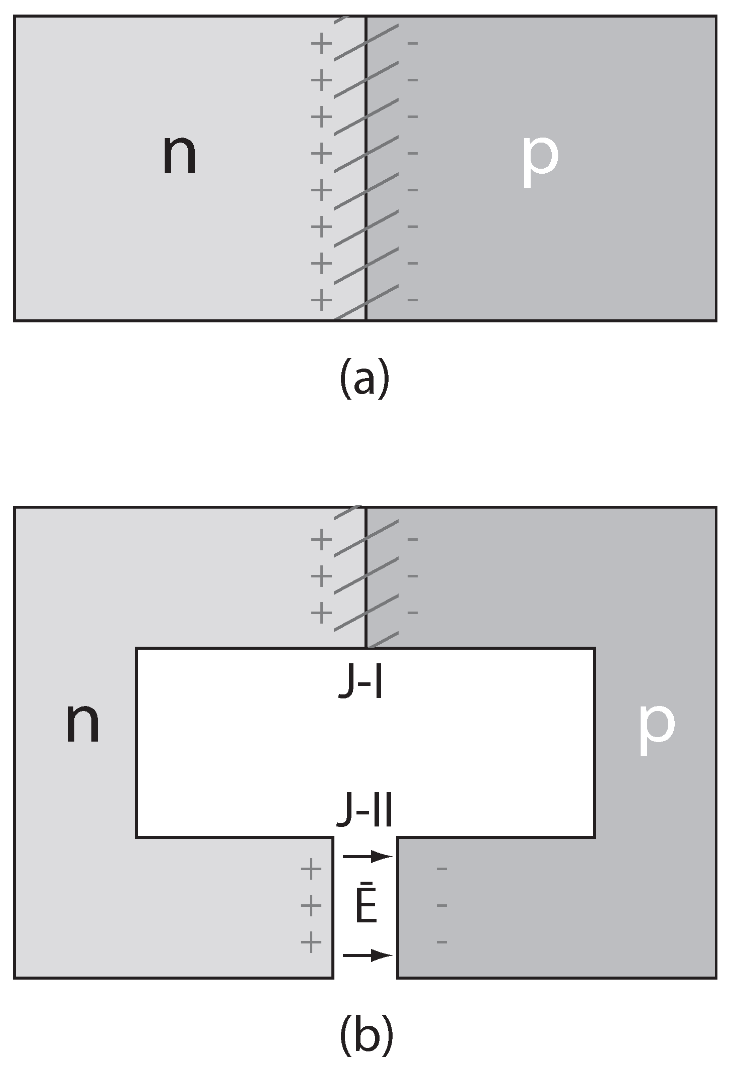
The following is a summary of a particular solid state technology that might have applications to SL-IRSM. It should operate over a broad temperature range (T = 100–1,000 K), be capable of high power densities, and be amenable to fabrication within the current state-of-the-art of micro- and nano-manufacturing. Detailed analyses can be found elsewhere [9,10,11]. It is well known that when n- and p-doped silicon are joined (forming a standard p-n diode) an electrostatic potential difference (built-in potential, = 0.5–1 V) arises across its junction, the so-called depletion region (0.01 10 ), as shown in Figure 1a. Local electric fields can be intense ( V/m), storing appreciable electrostatic energy. The built-in potential depends on temperature and acceptor () and donor () doping concentrations [97]:
where q is an electronic charge, and is the intrinsic charge carrier concentration in the pure semiconductor. (For silicon, m at 300 K.)
Figure 1.
Thermal diodic capacitor (TDC). (a) Semiconductor p-n diode with n- and p-region indicated. Depletion region indicated by slash lines. (b) TDC horseshoe structure. Depletion region at J-I biases vacuum gap (J-II) to . Surface charges and vacuum electric field indicated.
Figure 1.
Thermal diodic capacitor (TDC). (a) Semiconductor p-n diode with n- and p-region indicated. Depletion region indicated by slash lines. (b) TDC horseshoe structure. Depletion region at J-I biases vacuum gap (J-II) to . Surface charges and vacuum electric field indicated.

Consider a p-n diode shaped like a horseshoe (Figure 1b). At the top junction (J-I) is a regular p-n diode depletion region, while at the bottom (J-II) there is a vacuum gap. The built-in potential of the J-I depletion region will be expressed across the vacuum gap; this can be shown either via energy conservation (Kirchhoff’s loop law) or Faraday’s law. This gap electric field has been verified by commercial semiconductor device simulators (e.g., Silvaco International—Atlas), as is implied by numerous condensed matter experiments using Kelvin probes [98,99]. Direct measurements of diode-induced gap electric fields and potentials were recently measured in micron and sub-micron air gaps in diodic silicon devices using scanning Kelvin probe microscopy (SKPM) and electric field microscopy (EFM) [100]. Results verified theoretical and numerical predictions.
The gap electric field and its resultant electrostatic pressure and energy density can be appreciable. For V and gap width m, for example, the gap field is V/m, with electrostatic pressure Pa and energy density J/m. This thermal diodic capacitor (TDC) can exist in two distinct equilibrium states—a high-energy (vacuum gap open) configuration and a low-energy (gap closed) configuration—and can be mechanically switched between them, exploiting their energy difference in the process. As such, a TDC can perform net work in a thermodynamic cycle, but in doing so it must subvert the second law.
Several challenges to the second law have been proposed based on TDCs [9,10,11], embodied in nano- and micro-electro-mechanical devices (NEMS and MEMS) [101,102,103,104]. Laboratory research is pursuing several devices, including a MEMS torsional oscillator shown in Figure 2. In this device, the top piece (p-type semiconductor) consists of an oscillator mass (the hammer) attached by flexible torsional springs to a supporting frame. It rests on an n-type base (the anvil), thus forming a p-n diode. The built-in voltage is expressed across the vacuum gap between the p-type hammer and the n-type anvil, as in the case of the horseshoe diode (Figure 1b).
Figure 2.
Semiconductor p-n diodic torsional oscillator. (a) Perspective view. (b) Cut-away side view. Slashed areas indicate depletion regions.
Figure 2.
Semiconductor p-n diodic torsional oscillator. (a) Perspective view. (b) Cut-away side view. Slashed areas indicate depletion regions.
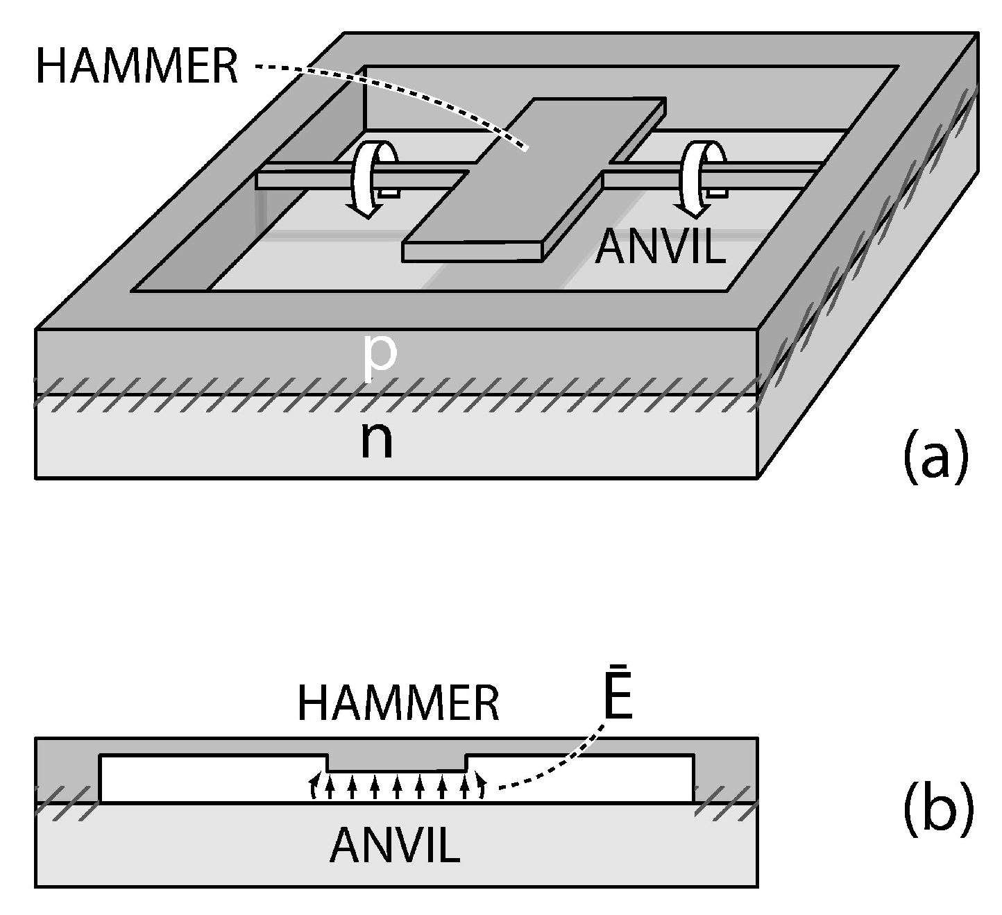
The hammer-anvil is predicted to be electromechanically unstable. Negative electrostatic pressure in the gap attracts the hammer toward the anvil, twisting the torsion fibers. When the hammer contacts the anvil and electrically discharges, the gap field collapses, allowing the torsional springs to retract it. The hammer and anvil mechanically reset and recharge, allowing the cycle to repeat. Detailed analysis verifies this scenario for a variety of high-Q MEMS and NEMS oscillators (e.g., cantilevered [11], linear [9], rotary [10]). Numerical simulations indicate a broad and experimentally accessible parameter space in which each should be viable. Transduction of their motion into electricity is possible by several means, including piezoelectric stress, thermoacoustics, and Faraday induction. Prototype torsional oscillators have been fabricated and are under active study.
Dimensionally, power density output for SL-oscillators should scale as , where is the vacuum gap’s electrostatic energy density ( (J/m)) and f (Hz) is oscillation frequency. The maximum theoretical power density of NEMS-based SL-devices is substantial. Taking E to be the dielectric strength of silicon ( V/m) and the frequency to be that of state-of-the-art NEMS resonators ( GHz), the upper-limit theoretical power density should be Wm. Practical considerations—e.g., realistic mechanical packing, heat transfer, fluid flow, output power coupling—would probably reduce steady-state power flux densities by – of this. This assumes a steady throughput of heat feedstock to keep the SL-devices warm. Taking Wm as a baseline, micron-thick panels could, in principle, achieve areal power densities of about Wm.
Consider fluid passing through an SL-power generator with velocity V and let its temperature drop be between entrance and exit. The net output convective thermal power for the fluid is given by: , where ρ is the mass density of the fluid, C is its specific heat, and is the surface area of the SL-power generator contacting the fluid. This is heat power that, theoretically, can be converted into electromechanical power by the SL-generator. The fluid, however, cannot give up its heat faster than the SL-generator surfaces can accept it, therefore, it is required that the heat power extracted by the generator via conduction in its surfaces () match the convective power available from the fluid (). The heat conduction power can approximated by thermal power conduction in slab geometry: , where k is the thermal conductivity of the heat exchanging surfaces, and x is their thickness. Finally, the maximum power output of the SL-generator itself is given by the power flux density of TDCs multiplied by their total volume: . If these three powers are comparable—that is, if —then thermodynamically the SL-generator could achieve its target power rating.
Energy feedstock for SL-power units will most conveniently be air or water, both of which possess substantial thermal energy density. For comparison, the thermal energy content of one liter of water at room temperature is roughly equivalent to the chemical energy of 100 grams of TNT. (The thermal energy flux of a small river could power a large city. The Ohio River, with its average discharge of nearly m/s, possesses enough thermal energy, in principle, to supply the electrical power needs of the entire United States.) In practice, the thermal energy content of almost any environment should be adequate to meet its energy needs. As a convecting fluid, air has advantages over water in being easier to handle and more ubiquitous, and it also allows greater temperature variations ; on the other hand, it has lower mass density and specific heat (). As discussed in Section 4, SL-power densities seem adequate to propel most types of vehicles on land, sea or air.
4. Strategies and Applications of SL-IRSM
SL-IRSM has the potential to be disruptive across the spectrum of IRSM technologies, applications and strategies, including camouflage, surveillance, night vision, homing, tracking, and target acquisition. This section will focus on two representative scenarios that highlight key aspects of SL-IRSM: a buried military installation and an aircraft jet engine. Although the former is not ostensibly aeronautical, it introduces thermodynamic ideas instructive to the latter; moreover, its application to suppression of aircraft skin emissions should become apparent.
4.1. Subsurface Installation
Consider a self-contained underground installation (e.g., a C4 center, missile silo, or chemical/nuclear facility) whose interior temperature () is greater than that of the earthen substrate in which it is buried (), and whose IR signature at ground level is to be minimized. Such an installation is expected to house active power-consuming devices (e.g., lights, heaters, computers, refrigerators, air conditioners, motors), which ultimately convert nearly all their mechanical, chemical, or electrical energy into heat. Since the second law demands that heat spontaneously flow down a temperature gradient, the installation’s heat flows naturally toward the ground surface; thus, to avoid detection, heat production and leakage from the installation should be minimized.
To a first approximation, one might suppose that simply adding thermal insulation to the installation, thereby trapping the heat inside, should suffice. A multi-walled Dewar would seem ideal because it is designed to thwart all three types of heat transfer. (Linde AG, an international industrial gases and engineering company, reportedly has fashioned Dewars capable of keeping a cup of tea warm for 10,000 years.) Thermodynamically, however, this strategy would fail because the steadily accumulating trapped heat will ultimately cook the contents of the installation. Next, one might consider installing a refrigerator to counteract the heat build-up, but this would only exacerbate the problem because, as one version of the second law states, there are no perfectly efficient refrigerators. The waste heat from the refrigerator would add to the accumulating heat and hasten the installation’s thermal demise. (An effective—and inefficient—way to heat a home is to leave the refrigerator door open in the kitchen.)
A more reasonable solution might be to outfit the installation with a heat pump and a large thermal reservoir into which waste heat can be dumped (e.g., a large, thermally-insulated tank of cold brine), so as to increase the installation’s thermal effusivity. While this is better than the two previous proposals, it offers only a temporary solution because even the reservoir will eventually heat up, at which point one faces the previous refrigerator dilemma. Ultimately, none of these “solutions” address the underlying issue: the generation of waste heat. SL-heat converters could address this issue directly since they convert heat into work, thereby eliminating it. In effect, they are self-powered, perfectly efficient refrigerators. Furthermore, heat is now not only eliminated, it becomes a source of recyclable energy, a quality distinct from any other energy source.
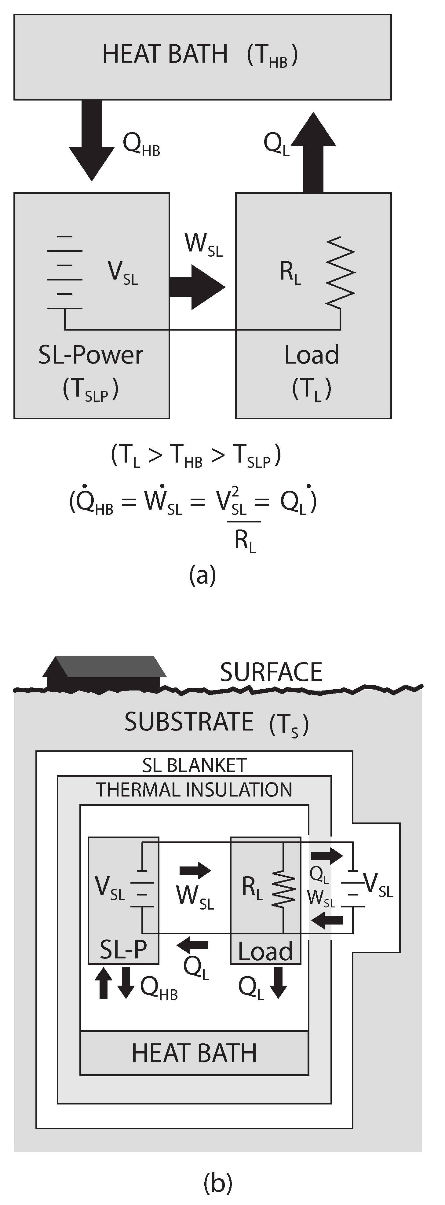
Consider how an everyday ventilation fan might operate. Electricity from an SL-power unit, which cools down relative to the installation as it produces electrical power, drives the fan’s motor (which heats slightly due to its electromechanical inefficiencies). The fan blades mechanically drive macroscopic currents of air around the installation. The heat from the fan’s motor diffuses into the air; the macroscopic air currents decay away, also producing heat; the fan’s sound waves damp and heat the installation’s walls. Ultimately, all the fan’s electrical input power degrades into waste heat. Now, since the SL-power unit is cooler than the continually heated installation interior, the Clausius form of the second law ensures that heat naturally flows into it, such that it can continue to power the fan. The thermodynamic cycle is depicted in Figure 3a, with the fan replaced by a generic electrical load. Notice that this is a closed thermodynamic loop; no external free energy sources are necessary and, in principle, it can be maintained indefinitely.
As exemplified by the fan, the entire underground installation (to first order) can be considered a closed thermodynamic system where work is degraded into heat and then recycled by SL-power units back into work again for reuse. Under steady-state conditions—that is, when all systems are run steadily at fixed power levels—the installation neither generates nor consumes any net heat or work. There is no heat build-up in the installation.
SL-power addresses the first issue, waste heat production, but the issue of heat leakage remains. According to Fourier’s law of heat conduction, the heat flux out of the installation () will be proportional to the negative of the temperature gradient: , where is the coefficient of thermal conductivity of the walls, and is the thickness of the thermal insulation around the installation. Clearly, a thick, low-conductivity thermal blanket layer would be best for IRSM.
Figure 3.
SL-IRSM for underground installation. (a) SL-heat cycle. SL-power unit drives load, which exhausts heat to heat bath, which in turn returns to power unit, via temperature gradients. (b) Heat and work flows.
Figure 3.
SL-IRSM for underground installation. (a) SL-heat cycle. SL-power unit drives load, which exhausts heat to heat bath, which in turn returns to power unit, via temperature gradients. (b) Heat and work flows.

SL-IRSM can be implemented by: (i) installing SL-heat converters inside the installation to soak up heat as it is generated; and (ii) encasing the entire installation in a thick thermally-insulating blanket within a secondary array of SL-units. The SL-array captures and converts into work any residual escaping heat, redirecting it back into the installation core for either reuse or sequestering, or to maintain the core temperature, (See Figure 3b). In steady-state operation, the net heat power generated by the installation will be constant, thus it must be soaked up either by the SL-blanket or by SL-heat converters in the interior. The best way to reduce the load on the SL-blanket is to soak up the heat inside the installation as soon as it is produced, before it has the opportunity to diffuse into the walls. This can be facilitated by adding thermal insulation with large thermal effusivity around the installation so as to slow the outward heat diffusion, thus giving the interior SL-heat converters more opportunity to work. The outer SL-thermal blanket would sop up residual heat. (Recall that SL-panels might have power densities in excess of Wm.)
There are, of course, secondary effects and caveats for this analysis to hold, but most can be addressed in a straightforward manner. Humans generate roughly 100–200 W of heat continuously under sedentary conditions. If not addressed, human-generated heat could conceivably either leak to the surface or cook the installation’s interior. The waste heat from a single person for one day could be sequestered as chemical energy in roughly 30 kg of a Na-S battery. On the other hand, some of this energy could be used to scrub CO or other waste gases from the installation’s atmosphere, or it could be used for oxygen regeneration, thus helping make the installation not only thermodynamically self-sufficient, but also chemically and biologically sustainable.
Heat sequestering need not be as exotic as chemical batteries; it can consist of merely a large thermal reservoir, e.g., a tank of water. The waste heat from one person for one day would raise the temperature of one cubic meter of water about 4 K; thus, a 500 cubic meter reservoir heated from 20 °C to 80 °C could accommodate the waste heat of a 10-persons crew for 2 years, not even accounting for offsets from oxygen regeneration and CO scrubbing. (Through catalytic means, explored elsewhere [94], in principle, the crew’s chemical energy might even be reconstituted as new organic compounds, like sugars or petroleum, thus obviating the thermal reservoir.) Because heat is the feedstock for SL-power, the heat reservoir acts as an SL-battery.
The areal power densities of proposed SL-panels are adequate to handle heat loads for realistic installations. As a concrete example, consider a cubical bunker, 10 meters on a side, with total heat power generation of 100 kW. Its power density is about 20–30 times that of a typical American home, presumably because it is densely packed with electronic and mechanical hardware. With nominal SL-panels ( Wm) over its 600 m of exterior surface, the total heat recycling capability of its SL-blanket (Figure 3b) would be W, several times its 100 kW heat generation. (This neglects potential internal heat recycling, which could handle heat production directly at its source.)
The installation must contend with the daily, seasonal, and mission-related changes in heat flow of the earth surrounding it. Thermometers in the SL-blanket might provide feedback to the individual SL-panels making up the blanket so as to adjust heat flow in, out and around the installation in order to mimic the natural heat flow and temperature of the substrate. In this way, the installation might be rendered thermally indistinguishable from its surroundings, hence IR-invisible from the surface, even while the temperature difference is maintained. In some respects, this is the thermal analog to an electromagnetic metamaterial cloak by which radiation is routed around the region of space to be camouflaged.
This second law option generates two mutually-reinforcing solutions. It allows the installation to operate as a closed, self-sustaining energy (and perhaps chemical) system with access to an effectively inexhaustible energy supply. Simultaneously, heat generation is neutralized, thereby reducing the potential for heat leakage to the surface. In principle, all the generated heat would be captured and converted inside the installation, or as it diffuses outward through its walls. This analysis also pertains to above-ground installations, although camouflage in the optical region of the spectrum must then be addressed. (Of course, even for underground system other detection modes are not ruled out; for instance, ground penetrating radar.) Aeronautical applications can also be envisioned, for instance, the cooling of fuselage skins heated by aerodynamic drag or by internally generated heat.
4.2. SL-Turbojet
Aircraft IR signatures arise from several sources, including (a) emissions from heated parts (e.g., exhaust nozzle, tailpipe), the exhaust plume (primarily hot CO and HO), and the aerodynamically-heated and plume-heated aircraft skin; and (b) IR reflected off the airframe from the earth (earthshine), sky (skyshine), and sun (sunshine). Type (a) emissions can be addressed most directly by SL-IRSM.
Military aircraft require IRSM owing primarily to the IR signatures from their engines. Arsenals of air-to-air and surface-to-air heat seeking missiles have been developed to defeat them, while a phalanx of anti-missile flares, modulated and directional IR countermeasures (IRCM) have developed around them. This expensive, half-century old infrared arms race has been fueled directly by the second law.
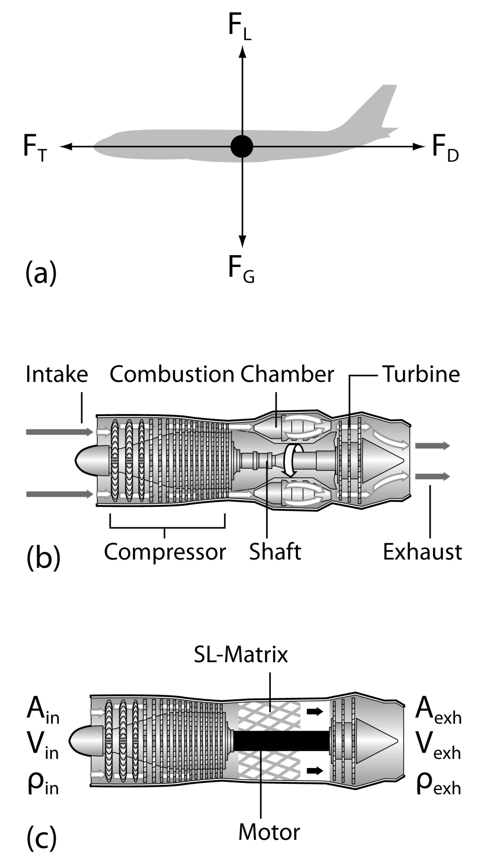
This section explores the prospects for using SL-heat converters to simultaneously IR-cloak and propel aircraft. Consider a jet aircraft cruising in level flight whose free body force diagram is given in Figure 4a. Gravitational force downward () is balanced by lift (), while horizontal thrust () is balanced by drag (). Discussion will focus on the turbojet engine configuration (Figure 4b). Air is taken into the front of the engine and compressed by the compressor (to 3–12 times its original pressure), at which point it is mixed with fuel and burned in the combustion chamber. The resultant high-temperature, high-pressure exhaust gas passes through a turbine, which drives the compressor, and then exits the back nozzle of the engine, providing thrust (). Here is the exhaust velocity of the gas and is the mass flux of the exhaust gas. Additional fuel added after the turbine can increase thrust by up to 40%, constituting an afterburner, which can increase its IR signature by an order of magnitude [3]. The maximum net thermodynamic efficiency of a turbojet engine is about 30%.
As depicted in Figure 4c, one can imagine a SL-based turbojet in which the combustion chamber is replaced with a matrix of semiconductor SL-devices that convert heat from the incoming air stream into electricity, which in turn powers an electric motor concentric with the compressor-turbine drive shaft. Ambient-temperature air enters the engine at the front, is forced by the compressor through the SL-heat converter, and provides engine thrust by an exiting stream of cold, high-velocity gas. It exits cold because some of its thermal energy has been converted into the directed mass motion (horizontal velocity ). In effect, the perpendicular kinetic energy of the incoming air molecules has been converted into horizontal kinetic energy of the exhaust stream.
A rudimentary analysis of the SL-turbojet can be made via consideration of its mass, linear momentum, and energy conservation. Referring to Figure 4c, expressions for conservation of mass, linear momentum, and energy can be written respectively as:
Here in and exh refer to input and exhaust respectively, is mass flux (kg/s), A is the cross sectional area of either input and exhaust ports, V is air velocity into or out of the engine, and T is gas temperature. is the specific heat of air () and is the power loss due to aircraft skin heating, sound, shock waves, or other channels not associated with thrust. Finally, α is a phenomenological measure of the aerodynamic shape and cross section of the aircraft. Inasmuch as it enters through linear momentum (force) Equation (6), α represents a scaling factor for the thrust necessary to balance the drag forces, as indicated by the force diagram (Figure 4a). For physical reasonableness, .
Figure 4.
SL-Turbojet. (a) Force diagram for SL-jet, indicating aerodynamic lift () and drag (), gravitational force (weight ), and thrust (). (b) Standard turbojet engine. (c) SL-turbojet engine.
Figure 4.
SL-Turbojet. (a) Force diagram for SL-jet, indicating aerodynamic lift () and drag (), gravitational force (weight ), and thrust (). (b) Standard turbojet engine. (c) SL-turbojet engine.

The aircraft’s steady-state level-flying cruise velocity () can be estimated from (5)–(7). Dividing (6) by (5) renders . Inserting this into (7) and solving for , one obtains:
with . If thermal conversion dominates over non-thrust losses, such that , then (8) can be simplified to:
Notice that in this model the resultant jet velocity depends on and α, while such things as air density (altitude), air intake rate, and exhaust cross sections are not explicitly germane.
Air starting at typical atmospheric temperatures ( K) can undergo significant cooling ( K) before it liquefies (the boiling points of N and O are 77 K and 90 K, respectively). Meanwhile, silicon SL-power units can operate down to roughly liquid nitrogen temperatures before the semiconductor’s charge carriers freeze out, rendering the doped silicon intrinsic, thereby quenching the built-in potential (Equation 4) upon which the second law effect depends. Therefore, in principle, the SL-jet engine could cool its input air perhaps by as much as K—and extract appreciable heat in the process—before cooling becomes problematic.
In Figure 5, is plotted versus α for several values of , based on (9). For example, for and K, one finds a theoretical jet velocity of m/s. Clearly, more sophisticated analysis is called for; however, several trends can be inferred from this simple model.
Figure 5.
SL-jet velocity () versus aerodynamic coefficient (α) for various temperatures differences ( = 200 K, 100 K, 50 K), based on (9).
Figure 5.
SL-jet velocity () versus aerodynamic coefficient (α) for various temperatures differences ( = 200 K, 100 K, 50 K), based on (9).
First, the infrared signature of the SL-engine should be significantly reduced compared with that of a standard chemically-driven turbojet. In fact, an SL-engine will produce no net heat under level, steady-state flying conditions—unlike a typical jet engine that might output 100 MW or more in heat. Although it produces no net heat, this is not to say that it will be infrared invisible; rather, its infrared signature now becomes an issue of how the hot and cold air around the aircraft is distributed, the local aerodynamic heating of the airframe, as well as what its intrinsic contrast against atmospheric background might be, e.g., reflected IR from the sun, sky, and earth. (Furthermore, this analysis pertains to aircraft fly level and at a constant speed; for instance, as an SL-aircraft climbs or accelerates there should be a net cooling of the surrounding air as additional heat is converted into thrust power, while as it decelerates net heat will be deposited in the surrounding air, giving a net positive IR signature.) If the air behind the SL-engine is well-mixed, and if the aircraft does not produce significant sound, wave disturbances, skin heating or other non-thrust losses (i.e., the condition pertinent to (9) is met), then the air behind the engine should be at nearly the same temperature as the air going in. In the limit of perfect mixing and , the aircraft should produce no net infrared emissions over the background air in which it flies. This would constitute broadband emission-based IR stealth or cloaking. On the other hand, even if the full cooling produced by SL-heat converters were expressed in the exhaust stream of the SL-engine, this negative apparent temperature difference would still be roughly an order of magnitude less than for a traditional jet engine, and thus its contrast radiant intensity should be 2–4 orders of magnitude less. Again, it is emphasized that for real aircraft, IR signatures are not determined solely from IR emissions as treated here; rather, they are greatly dependent on such things as IR reflected from its environment (e.g., sun, sky, clouds, ground) and non-unity emissivities.
Second, because the thermal energy of air is the energy source for SL-jets, there would seem to be little need to carry chemical jet fuel onboard. The size and weight of SL-aircraft might thus be significantly reduced, payloads increased, and aircraft’s time aloft not dictated by fuel capacity; after all, an SL-jet flies in its own fuel. (The weight of fuel for ships and aircraft is often a sizable fraction of their total weight.) Also, since engines presumably would operate at lower temperatures and under less hostile chemical environments than traditional chemical engines, they should also suffer less thermal fatigue and chemical degradation, perhaps requiring less exotic and expensive construction materials and upkeep.
Third, an SL-engine would not consume chemical fuels and therefore would leave behind little or no chemical exhaust products or pollutants. Because they would not produce water vapor or soot particles, which can seed contrails, their stealth capabilities might be improved; however, because the local exhaust plume would be cold, ambient water vapor might condense temporarily. Compared with traditional ones, SL-aircraft should be relatively benign environmentally.
In principle, jet fuel can be used to augment the thrust of an SL-engine or to favorably tune its IR signature. In contrast to a traditional afterburner, this fuel would be injected at the front end of the engine, between the compressor and the SL-matrix (Figure 4c), rather than after the turbine (Figure 4b). Fuel augmentation would play a dual role. First, fuel could directly add to engine thrust by increasing mass flux and thermal energy (via chemical combustion). Equations (5)–(7) can be modified to include fuel mass input () and the additional thermal energy gained from burning the fuel. (It is assumed here that the chemical energy of the fuel is fully thermalized and thoroughly mixed with the air.)
Under the reasonable assumption that , or equivalently , it can be shown that modifications to (5)–(7) lead to:
If non-thrust parasitic losses are negligible, i.e., if , one obtains
Here is the specific heat of the air-chemical exhaust mixture, which is taken here to be roughly the same as that of pure air (), and between the combustion exhaust and input air, now assumed to be larger than in the no-fuel case (i.e., ). Since combustion temperatures can be high ( K), and if the SL-power unit can efficiently convert thermal energy to work, then can be much larger than for the non-fuel configuration, in which case (11) predicts increased jet velocity, as expected.
A second potential advantage of fuel augmentation is to favorably tune the exhaust temperature of the SL-engine so as to minimize its IR signature. (This, of course, must be weighed against potential disadvantages such as increased mechanical complexity, chemical and vapor trails.) Recall that the wake of an SL-aircraft might be cooler than the ambient air, thereby creating a negative temperature contrast (heat shadow) or condensation trail, especially if it mixes imperfectly with the turbulence behind the aircraft, or before its directed kinetic energy is thermalized, or if parasitic losses (e.g., ) carry away significant power. It should be possible to reduce this negative IR contrast by producing a little extra local heat through judicious fuel burning.
As a further conceptual simplification to the engine, let the SL-heat converter matrix (Figure 4c) be removed and the microscopic SL-heat converters be integrated directly into the surfaces of the compressor and turbine blades. The blades would now double as heat converters. Since by their very operation they are in intimate thermal contact with the air—their fuel—they should be able to withdraw heat effectively from it. Electrical power would still be routed to the coaxial motor.
As a simple numerical test of this integration concept, consider plausible physical parameters for such an SL-jet. Let the total cross sectional area of the aircraft in the direction of travel be m, the area opening of the SL-engine input be m, and the total surface area of the compressor blades (plus the interior walls of the engine) be m, and let the thickness of the SL-device layering on the blades and engine interior be m. Let the thermal conductivity of the blades and engine walls be metallic ( W/°Cm), and let the temperature difference between the air flowing through the engine and the blade surfaces be maintained at K so heat will flow into the blade. Let the total net cooling of the air through the engine be K, as in (8)–(11).
In this scenario, the heat flux from the air to the compressor blades and walls should be in the order of W. The maximum theoretical power output from this volume of SL-devices layered on the blades and walls should be: W. The change in thermal energy content of the air passing through the engine for is also comparable: W. Finally, the mechanical power required to overcome air drag can be estimated as W. Given that , this scenario is thermodynamically plausible—aside from its obvious violation of the second law.
In summary, it appears possible in principle to both propel and IR-cloak aircraft using SL-IRSM technology.
5. Discussion, Outlook and Conclusions
This article brings together for the first time two previously disconnected subjects—second law challenges and IR stealth and cloaking—and finds strong affinities between them. SL-IRSM could be transformative for many IRSM technologies, applications, and strategies. This should include manned and unmanned vehicles, weapons, sensors, and even perhaps personnel uniforms. Gas turbine engines, for example, are standard power plants for helicopters and tanks as well as for jet aircraft. It could have serious ramifications for target acquisition, tracking, and homing of such systems as heat-seeking missiles and on countermeasures, like flares.
Although SL-IRSM seems most pertinent to active targets, it might also be adaptable to passive targets insofar as background heat fluxes can betray the existence of a target. Micron-thin SL-panels might offer both rapid and local cooling or heating of surfaces so as to blend into an environment. (Recall that the theoretical power densities of micron-thick SL-panels exceed solar power densities.)
Until now, the growing second law literature has concentrated on energy-related applications, for understandable reasons. This article attempts to broaden interest through a compelling new application. Whereas the mind of the scientific community has been essentially closed to discussion of the status of the second law for more than a century, and the conventional energy energy industry has a vested interest in not discussing disruptive, non-fossil energy sources, the military has traditionally been open to new science and technology—for obvious reasons of advantage and survival. In fact, most of the trappings of the modern world—nuclear physics and energy, solid-state electronics and material science, aeronautics and astronautics, computers and the Internet—were championed first by the military, and only later were adopted in the civilian sphere. Perhaps this will also be so with IR-SL technology.
Looking ahead, SL-heat recycling technology has been proposed as part of the recent NASA-DARPA collaboration, 100-Year Starship Initiative (100YSS), which is exploring technologies whereby a starship might be created by the latter half of the 21st century. Interstellar travel presents a constellation of challenges, the chief challenge among which being the power sources to sustain the spacecraft and its crew during transit and at their final destination. Chemical energy sources are probably inadequate for long-term missions, having energy densities less than about 20 MJ/kg, and while fission and fusion boast high energy densities, with mass-to-energy conversion fractions of about 0.001 and 0.01 respectively, their hardware is complex and massive, and their radiation is problematic. One of the leading candidates for starship power is the SL-heat recycler [105], a natural extension of the SL-IRSM.
For now, the road to SL-IRSM is uncertain. First, although the second law appears vulnerable from a theoretical standpoint, the ultimate proof of its violability can only (and is still yet to) be provided by experiment alone. Even then, the technical feasibility of SL-IRSM is an entirely separate issue. Still, as this study attempts to demonstrate, the high stakes of second law subversion seem to warrant a thoughtful look over the horizon. Given the many theoretical challenges and the good outlook for experiments, this author predicts that the first experimental violation of the second law will be recognized within the next five years, in which case the heat will most certainly be turned up on IRSM.
Acknowledgments
This work was performed, in part, at the Center for Integrated Nanotechnologies, a U.S. Department of Energy, Office of Basic Energy Sciences user facility at Los Alamos National Laboratory (Contract DE-AC52-06NA25396) and Sandia National Laboratories (Contract DE-AC04-94AL85000). The author is grateful to B. Cragin for his technical illustrations. The author also thanks the two anonymous reviewers. This paper is dedicated to the memories of M.P.S, M.J.S., P.C.S. and W.F.S.
References
- Jacobs, P.A. Thermal Infrared Characterization of Ground Targets and Backgrounds, 2nd ed.; SPIE Press: Bellingham, WA, USA, 2006. [Google Scholar]
- Kaplan, H. Practical Applications of Infrared Thermal Sensing and Imaging Equipment, 3rd ed.; SPIE Press: Bellingham, WA, USA, 2007. [Google Scholar]
- Mahulikar, S.P.; Sonawane, H.R.; Rao, G.A. Infrared signature studies of aerospace vehicles. Prog. Aerospace Sci. 2007, 43, 218–245. [Google Scholar] [CrossRef]
- von Baeyer, H.C. Warmth Disperses and Time Passes: The History of Heat; The Modern Library: New York, NY, USA, 1998. [Google Scholar]
- First International Conference on Quantum Limits to the Second Law; Sheehan, D.P. (Eds.) AIP Conference Proceedings. San Diego, CA, USA, 28–31 July 2002; AIP Press: Melville, NY, USA, 2002; Volume 643.
- Čápek, V.; Sheehan, D.P. Challenges to the second law of thermodynamics. In Fundamental Theories of Physics; Springer: Dordrecht, The Netherlands, 2005; Volume 146. [Google Scholar]
- Sheehan, D.P. (Ed.) The second law of thermodynamics: Foundations and status. In Proceedings of Symposium at 87th Annual Meeting of the Pacific Division of AAAS, University of San Diego, San Diego, CA, USA, 19–22 June 2006; Springer: Dordrecht, The Netherlands, 2007.
- Second Law of Thermodynamics: Status and Challenges; Sheehan, D.P. (Eds.) AIP Conference Proceedings. San Diego, CA, USA, 14–15 June 2011; AIP Press: Melville, NY, USA, 2011; Volume 1411.
- Sheehan, D.P.; Wright, J.H.; Putnam, A.R. A solid-state Maxwell demon. Found. Phys. 2002, 32, 1557–1595. [Google Scholar] [CrossRef]
- Wright, J.H.; Sheehan, D.P.; Putnam, A.R. Modeling a submicrometer electrostatic motor. J. Nanosci. Nanotech. 2003, 3, 329–334. [Google Scholar] [CrossRef]
- Sheehan, D.P.; Wright, J.H.; Putnam, A.R.; Perttu, E.K. Intrinsically biased, resonant NEMS—MEMS oscillator and the second law of thermodynamics. Physica E 2005, 29, 87–99. [Google Scholar] [CrossRef]
- Uffink, J. Bluff your way in the second law of thermodynamics. Studies Hist. Phil. Mod. Phys. 2001, 32, 305–394. [Google Scholar] [CrossRef]
- Leff, H.S.; Rex, A.F. Maxwell’s Demon 2: Entropy, Classical and Quantum Information, Computing; Institute of Physics Publishing: Bristol, UK, 2003. [Google Scholar]
- Ergin, T.; Stenger, N.; Brenner, P.; Pendry, J.B.; Wegener, M. Three-dimensional invisibility cloak at optical wavelengths. Science 2010, 328, 337–339. [Google Scholar] [CrossRef] [PubMed]
- Alu, A.; Engheta, N. Plasmonic and metamaterial cloaking: Physical mechanisms and potentials. Opt. A: Pure Appl. Opt. 2008, 10, 093002. [Google Scholar] [CrossRef]
- Pendry, J.B.; Schurig, D.; Smith, D.R. Controlling electromagnetic fields. Science 2006, 312, 1780–1782. [Google Scholar] [CrossRef] [PubMed]
- Schurig, D.; Mock, J.J.; Justice, B.J.; Cummer, S.A.; Pendry, J.B.; Starr, A.F.; Smith, D.R. Metamaterial electromagnetic cloak at microwave frequencies. Science 2006, 314, 977–980. [Google Scholar] [CrossRef] [PubMed]
- Cummer, S.A.; Popa, B.I.; Schurig, D.; Smith, D.R. Full-wave simulations of electromagnetic cloaking structures. Phys. Rev. E 2006, 74, 036621. [Google Scholar] [CrossRef] [PubMed]
- Cai, W.; Chettiar, U.K.; Kildishev, A.V.; Shalaev, V.M. Optical cloaking with metamaterials. Nat. Photon. 2007, 1, 224–227. [Google Scholar] [CrossRef] [Green Version]
- Leonhardt, U. Optical conformal mapping. Science 2006, 312, 1777–1780. [Google Scholar] [CrossRef] [PubMed]
- Milton, G.W.; Nicorovici, N.A. On the cloaking effects associated with anomalous localized resonance. Proc. R. Soc. A 2006, 462, 3027–3059. [Google Scholar] [CrossRef]
- Milton, G.W.; Briane, M.; Willis, J.R. On cloaking for elasticity and physical equations with a transformation invariant form. New J. Phys. 2006, 8, 248. [Google Scholar] [CrossRef]
- Rumpf, R.C.; Fiddy, M.A.; Testorf, M.E. Design of generalized invisible scatterers. Opt. Express 2007, 15, 4735–4744. [Google Scholar] [CrossRef] [PubMed]
- Kerker, M. Abnormally low electromagnetic scattering cross sections. J. Opt. Soc. Am. 1976, 66, 445–449. [Google Scholar]
- Hoenders, B.J. Existence of invisible nonscattering objects and nonradiating sources. J. Opt. Soc. Am. A 1997, 14, 262–266. [Google Scholar] [CrossRef]
- Bohren, C.F.; Huffman, D.R. Absorption and Scattering of Light by Small Particles; Wiley: New York, NY, USA, 1983. [Google Scholar]
- Alú, A.; Engheta, N. Achieving transparency with plasmonic and metamaterial coatings. Phys. Rev. E 2005, 72, 016623. [Google Scholar] [CrossRef] [PubMed]
- Alú, A.; Engheta, N. Multifrequency optical invisibility cloak with layered plasmonic shells. Phys. Rev. Lett. 2008, 100, 113901. [Google Scholar] [CrossRef] [PubMed]
- Silveirinha, M.G.; Alú, A.; Engheta, N. Infrared and optical invisibility cloak with plasmonic implants based on scattering cancellation. Phys. Rev. B 2008, 78, 075107. [Google Scholar] [CrossRef]
- Greenleaf, A.; Kurylev, Y.; Lassas, M.; Uhlmann, G. Full-wave invisibility of active devices at all frequencies. Commun. Math. Phys. 2007, 275, 749–789. [Google Scholar] [CrossRef]
- Chen, H.; Jiang, X.; Chan, C.T. Extending the bandwidth of electromagnetic cloaks. Phys. Rev. B 2007, 76, 241104. [Google Scholar] [CrossRef]
- Yan, M.; Ruan, Z.; Qiu, M. Cylindrical invisibility cloak with simplified material parameters is inherently visible. Phys. Rev. Lett. 2007, 99, 233901. [Google Scholar] [CrossRef] [PubMed]
- Ruan, Z.; Yan, M.; Neff, C.W.; Qiu, M. Ideal Cylindrical cloak: Perfect but sensitive to tiny perturbations. Phys. Rev. Lett. 2007, 99, 113903. [Google Scholar] [CrossRef] [PubMed]
- Miller, D.A.B. On perfect cloaking. Opt. Express 2006, 14, 12457–12466. [Google Scholar] [CrossRef] [PubMed]
- Valagiannopoulos, C.A.; Alitalo, P. Electromagnetic cloaking of cylindrical objects by multilayer or uniform dielectric claddings. Phys. Rev. B 2012, 85, 115402. [Google Scholar] [CrossRef]
- Alitalo, P.; Tretyakov, S.A. Broadband electromagnetic cloaking realized with transmission-line and waveguiding structures. Proc. IEEE 2011, 99, 1646–1659. [Google Scholar] [CrossRef]
- Valagiannopoulos, C.A.; Tsitsas, N.L. Integral equation analysis of a low-profile receiving planar microstrip antenna with a cloaking superstrate. Radio Sci. 2012, 47, RS2022. [Google Scholar] [CrossRef]
- Eddington, A. The Nature of the Physical World; Everyman’s Library & J.M. Dent: London, UK, 1942. [Google Scholar]
- Gordon, L.G.M. Brownian movement and microscopic irreversibility. Found. Phys. 1981, 11, 103–113. [Google Scholar] [CrossRef]
- Gordon, L.G.M. Maxwell’s demon and detailed balancing. Found. Phys. 1983, 13, 989–997. [Google Scholar] [CrossRef]
- Gordon, L.G.M. The molecular-kinetic theory and the second law. J. Coll. Interf. Sci 1994, 162, 512–513. [Google Scholar] [CrossRef]
- Gordon, L.G.M. The decrease in entropy via fluctuations. Entropy 2004, 6, 38–49. [Google Scholar] [CrossRef]
- Denur, J. The Doppler demon. Am. J. Phys. 1981, 49, 352–355. [Google Scholar] [CrossRef]
- Denur, J. Velocity-dependent fluctuations: Breaking the randomness of Brownian motion. Phys. Rev. A 1989, 40, 5390–5399. [Google Scholar] [CrossRef] [PubMed]
- Denur, J. Modified Feynman ratchet with velocity-dependent fluctuations. Entropy 2004, 6, 76–86. [Google Scholar] [CrossRef]
- Denur, J. Speed-dependent weighting of the Maxwellian distribution in rarefied gases: A second-law paradox? Found. Phys. 2007, 37, 1685–1706. [Google Scholar] [CrossRef]
- Čápek, V. A thought construction of working perpetuum mobile of the second kind. Czech. J. Phys. 1996, 46, 1645–1652. [Google Scholar]
- Čápek, V. Isothermal Maxwell daemon and active binding of pairs of particles. J. Phys. A: Math. Gen. 1997, 30, 5245. [Google Scholar] [CrossRef]
- Čápek, V. Isothermal Maxwell daemon. Czech. J. Phys. 1997, 47, 845–849. [Google Scholar] [CrossRef]
- Čápek, V. Isothermal Maxwell demon as a quantum sewing machine. Phys. Rev. E 1998, 57, 3846–3852. [Google Scholar] [CrossRef]
- Čápek, V. Isothermal Maxwell daemon: Swing (fish-trap) model of particle pumping. Czech. J. Phys. 1998, 48, 879–901. [Google Scholar] [CrossRef]
- Čápek, V. From convolutionless generalized master to finite-coupling Pauli master equations. Czech. J. Phys. 1998, 48, 993–1012. [Google Scholar] [CrossRef]
- Čápek, V. Twilight of a dogma of statistical thermodynamics. Molec. Cryst. Liq. Cryst. Sci. Tech. Section A 2001, 355, 13–23. [Google Scholar] [CrossRef]
- Čápek, V.; Bok, J. Isothermal Maxwell daemon: numerical results in a simplified model. J. Phys. A: Math. Gen. 1998, 31, 8745. [Google Scholar] [CrossRef]
- Čápek, V.; Bok, J. Violation of the second law of thermodynamics in the quantum microworld. Physica A 2001, 290, 379–401. [Google Scholar] [CrossRef]
- Čápek, V.; Mančal, T. Isothermal Maxwell daemon as a molecular rectifier. Europhys. Lett. 1999, 48, 365. [Google Scholar] [CrossRef]
- Čápek, V.; Mančal, T. Phonon mode cooperating with a particle serving as a Maxwell gate and rectifier. J. Phys. A: Math. Gen. 2002, 35, 2111. [Google Scholar] [CrossRef]
- Čápek, V.; Tributsch, H. Particle (electron, proton) transfer and self-organization in active thermodynamic reservoirs. J. Phys. Chem. B 1999, 103, 3711–3719. [Google Scholar] [CrossRef]
- Čápek, V.; Frege, O. Dynamical trapping of particles as a challenge to statistical thermodynamics. Czech J. Phys. 2000, 50, 405–423. [Google Scholar] [CrossRef]
- Čápek, V.; Barvík, I. New aspects of the Davies weak coupling theory of quantum relaxation. Physica A 2001, 294, 388–402. [Google Scholar] [CrossRef]
- Čápek, V.; Sheehan, D.P. Quantum mechanical model of a plasma system: A challenge to the second law of thermodynamics. Physica A 2002, 304, 461–479. [Google Scholar] [CrossRef]
- Allahverdyan, A.E.; Nieuwenhuizen, Th.M. Extraction of work from a single thermal bath in the quantum regime. Phys. Rev. Lett. 2000, 85, 1799. [Google Scholar] [CrossRef] [PubMed]
- Allahverdyan, A.E.; Nieuwenhuizen, Th.M. Breakdown of the Landauer bound for information erasure in the quantum regime. Phys. Rev. E 2001, 64, 056117. [Google Scholar] [CrossRef] [PubMed]
- Allahverdyan, A.E.; Nieuwenhuizen, Th.M. Testing the violation of the Clausius inequality in nanoscale electric circuits. Phys. Rev. B 2002, 66, 115309. [Google Scholar] [CrossRef]
- Allahverdyan, A.E.; Nieuwenhuizen, Th.M. Statistical thermodynamics of quantum Brownian motion: Construction of perpetuum mobile of the second kind. Phys. Rev. E 2002, 66, 036102. [Google Scholar]
- Allahverdyan, A.E.; Nieuwenhuizen, Th.M. Bath-generated work extraction and inversion-free gain in two-level systems. J. Phys. A: Math. Gen. 2003, 36, 875. [Google Scholar] [CrossRef]
- Berger, J. The Chernogolovka experiment. Physica E 2005, 29, 100–103. [Google Scholar] [CrossRef]
- Berger, A nonconventional scenario for thermal equilibrium. Found. Physics 2007, 37, 1738–1743. [CrossRef]
- Crosignani, B.; Di Porto, P. Approach to thermal equilibrium in a system with adiabatic constraints. Am. J. Phys. 1996, 64, 610. [Google Scholar] [CrossRef]
- Crosignani, B.; Di Porto, P. On the validity of the second law of thermodynamics in the mesoscopic realm. Europhys. Lett. 2001, 53, 290. [Google Scholar] [CrossRef]
- Crosignani, B.; Di Porto, P. Random fluctuations of diathermal and adiabatic pistons. Found. Physics 2007, 37, 1707–1715. [Google Scholar] [CrossRef]
- Crosignani, B.; Di Porto, P.; Conti, C. The adiabatic piston and the second law of thermodynamics. In Quantum Limits to the Second Law; AIP Press: Melville, NY, USA, 2002; Volume 643, p. 267. [Google Scholar]
- Crosignani, B.; Di Porto, P.; Conti, C. The adiabatic piston: A perpetuum mobile in the mesoscopic realm. Entropy 2004, 6, 50–56. [Google Scholar] [CrossRef]
- Keefe, P. Coherent magneto-caloric effect heat engine process cycle. In Quantum Limits to the Second Law; AIP Press: Melville, NY, USA, 2002; Volume 643, p. 213. [Google Scholar]
- Keefe, P. Coherent magneto-caloric effect superconductive heat engine process cycle. J. Mod. Optics 2003, 50, 2443–2454. [Google Scholar] [CrossRef]
- Keefe, P. Second law violation by magneto-caloric effect adiabatic phase transition of type I superconductive particles. Entropy 2004, 6, 116–127. [Google Scholar] [CrossRef]
- Nikulov, A.V.; Zhilyaev, I.N. The Little-Parks effect in an inhomogeneous superconducting ring. J. Low Temp. Phys. 1998, 112, 227–235. [Google Scholar] [CrossRef]
- Nikulov, A.V. Quantum force in a superconductor. Phys. Rev. B 2001, 64, 012505. [Google Scholar] [CrossRef]
- Dubonos, S.V.; Kuznetsov, V.I.; Zhilyaev, I.N.; Nikulov, A.V. Observation of the external-ac-current-induced dc voltage proportional to the steady current in superconducting loops. JETP Lett. 2003, 77, 371–375. [Google Scholar] [CrossRef]
- Miller, S.L. Insights into the second saw of thermodynamics from anisotropic gas-surface interactions. Found. Phys. 2007, 37, 1660–1684. [Google Scholar] [CrossRef]
- Sheehan, D.P. A paradox involving the second law of thermodynamics. Phys. Plasmas 1995, 2, 1893. [Google Scholar] [CrossRef]
- Sheehan, D.P. Response to comment on “A paradox involving the second law of thermodynamics”. Phys. Plasmas 1996, 3, 706. [Google Scholar] [CrossRef]
- Sheehan, D.P. Another paradox involving the second law of thermodynamics. Phys. Plasmas 1996, 3, 104. [Google Scholar] [CrossRef]
- Sheehan, D.P. Four paradoxes involving the second law of thermodynamics. J. Sci. Explor. 1998, 12, 303. [Google Scholar]
- Sheehan, D.P. Dynamically-maintained, steady-state pressure gradients. Phys. Rev. E 1998, 57, 6660. [Google Scholar] [CrossRef]
- Sheehan, D.P. Reply to “Comment on ‘Dynamically maintained steady-state pressure gradients”. Phys. Rev. E 2000, 61, 4662. [Google Scholar] [CrossRef]
- Sheehan, D.P. The second law and chemically-induced, steady-state pressure gradients: Controversy, corroboration and caveats. Physica A 2001, 280, 185. [Google Scholar] [CrossRef]
- Sheehan, D.P. Thermosynthetic life. Found. Phys. 2007, 37, 1774. [Google Scholar] [CrossRef]
- Sheehan, D.P.; Means, J.D. Minimum requirement for second law violation: A paradox revisited. Phys. Plasmas 1998, 5, 2469. [Google Scholar] [CrossRef]
- Sheehan, D.P.; Glick, J.; Means, J.D. Steady-state work by an asymmetrically inelastic gravitator in a gas: A second law paradox. Found. Phys. 2000, 30, 1227. [Google Scholar] [CrossRef]
- Sheehan, D.P.; Glick, J. Gravitationally-induced, dynamically-maintained, steady-state pressure gradients. Phys. Script. 2000, 61, 635. [Google Scholar] [CrossRef]
- Sheehan, D.P.; Glick, J.; Duncan, T.; Langton, J.A.; Gagliardi, M.J.; Tobe, R. Phase space portraits of an unresolved Maxwell demon. Found. Phys. 2002, 32, 441. [Google Scholar] [CrossRef]
- Sheehan, D.P.; Glick, J.; Duncan, T.; Langton, J.A.; Gagliardi, M.J.; Tobe, R. Phase space analysis of a gravitationally-induced, steady-state nonequilibrium. Phys. Scripta 2002, 65, 430. [Google Scholar] [CrossRef]
- Sheehan, D.P.; Seideman, T. Intrinsically biased electrocapacitive catalysis. J. Chem. Physics 2005, 122, 204713. [Google Scholar] [CrossRef] [PubMed]
- Sheehan, D.P.; Gross, D.H.E. Extensivity and the thermodynamic limit: Why size really does matter. Physica A 2006, 370, 461. [Google Scholar] [CrossRef]
- Sheehan, D.P. Energy, entropy and the environment (How to increase the first by decreasing the second to save the third). J. Sci. Explor. 2008, 22, 459. [Google Scholar]
- Neudeck, G.W. Volume II: The pn Junction Diode , 2nd ed.; In Modular Series on Solid State DevicesPierret, R.F., Neudeck, G.W., Eds.; Addison-Wesley: Reading, UK, 1989. [Google Scholar]
- Sadewasser, S.; Glatzel, Th.; Shikler, R.; and Rosenwaks, Y. Resolution of Kelvin probe force microscopy in ultrahigh vacuum: comparison of experiment and simulation. Appl. Surf. Sci. 2003, 210, 32–36. [Google Scholar] [CrossRef]
- Kikukawa, A.; Hosaka, S.; Imura, R. Vacuum compatible high-sensitive Kelvin probe force microscopy. Rev. Sci. Instrum. 1995, 67, 1463–1467. [Google Scholar] [CrossRef]
- Sheehan, D.P.; Wright, J.H. Experimental measurements of electric fields in diodic air gaps: Toward a second law challenge. In Second Law of Thermodynamics: Status and Challenges. AIP Conference Proceedings, San Diego, CA, USA, 14–15 June 2011; AIP Press: Melville, NY, USA, 2011; Volume 1411, pp. 147–157. [Google Scholar]
- Bienstman, J.; Vandewalle, J.; Puers, R. The autonomous impact resonator: A new operating principle for a silicon resonant strain gauge. Sensor. Actuator. Phys. 1998, 66, 40–49. [Google Scholar] [CrossRef]
- Roukes, M.L. Nanoelectromechanical systems. In Proceedings of the Technical Digest of the 2000 Solid-State Sensor and Actuator Workshop, Hilton Head Island, SC, USA, 4–8 June 2000.
- Pelesko, J.A.; Bernstein, D.H. Modeling MEMS and NEMS; CRC Press: Boca Raton, FL, USA, 2003. [Google Scholar]
- Nanotechnology; Timp, G. (Ed.) Springer-Verlag: New York, NY, USA, 1999.
- Sheehan, D.P.; Wright, J.H. Heat recyclers for interstellar travel. In Presented at the 100 Year Starship Conference, Orlando, Fl, USA, 30 September–2 October 2011.
© 2012 by the author; licensee MDPI, Basel, Switzerland. This article is an open access article distributed under the terms and conditions of the Creative Commons Attribution license (http://creativecommons.org/licenses/by/3.0/).
Share and Cite
MDPI and ACS Style
Sheehan, D.P. Infrared Cloaking, Stealth, and the Second Law of Thermodynamics. Entropy 2012, 14, 1915-1938. https://doi.org/10.3390/e14101915
AMA Style
Sheehan DP. Infrared Cloaking, Stealth, and the Second Law of Thermodynamics. Entropy. 2012; 14(10):1915-1938. https://doi.org/10.3390/e14101915
Chicago/Turabian StyleSheehan, Daniel P. 2012. "Infrared Cloaking, Stealth, and the Second Law of Thermodynamics" Entropy 14, no. 10: 1915-1938. https://doi.org/10.3390/e14101915